EP0218306A2 - Gedämpfte Stationseinführungsvorrichtung für Seilbahnfahrzeuge - Google Patents
Gedämpfte Stationseinführungsvorrichtung für Seilbahnfahrzeuge Download PDFInfo
- Publication number
- EP0218306A2 EP0218306A2 EP86201733A EP86201733A EP0218306A2 EP 0218306 A2 EP0218306 A2 EP 0218306A2 EP 86201733 A EP86201733 A EP 86201733A EP 86201733 A EP86201733 A EP 86201733A EP 0218306 A2 EP0218306 A2 EP 0218306A2
- Authority
- EP
- European Patent Office
- Prior art keywords
- guide
- lead
- elastic elements
- outer support
- constrained
- Prior art date
- Legal status (The legal status is an assumption and is not a legal conclusion. Google has not performed a legal analysis and makes no representation as to the accuracy of the status listed.)
- Withdrawn
Links
- BTFMCMVEUCGQDX-UHFFFAOYSA-N 1-[10-[3-[4-(2-hydroxyethyl)-1-piperidinyl]propyl]-2-phenothiazinyl]ethanone Chemical compound C12=CC(C(=O)C)=CC=C2SC2=CC=CC=C2N1CCCN1CCC(CCO)CC1 BTFMCMVEUCGQDX-UHFFFAOYSA-N 0.000 title 1
- 229960004265 piperacetazine Drugs 0.000 title 1
- 229910000831 Steel Inorganic materials 0.000 claims description 2
- 239000013536 elastomeric material Substances 0.000 claims description 2
- 239000007787 solid Substances 0.000 claims description 2
- 239000010959 steel Substances 0.000 claims description 2
- 230000000295 complement effect Effects 0.000 claims 1
- 238000010521 absorption reaction Methods 0.000 description 2
- 230000010355 oscillation Effects 0.000 description 2
- 230000000903 blocking effect Effects 0.000 description 1
- 230000003139 buffering effect Effects 0.000 description 1
- 238000006243 chemical reaction Methods 0.000 description 1
- 230000007774 longterm Effects 0.000 description 1
- 230000008092 positive effect Effects 0.000 description 1
- 230000001737 promoting effect Effects 0.000 description 1
- 230000006641 stabilisation Effects 0.000 description 1
- 238000011105 stabilization Methods 0.000 description 1
Images

Classifications
-
- B—PERFORMING OPERATIONS; TRANSPORTING
- B61—RAILWAYS
- B61B—RAILWAY SYSTEMS; EQUIPMENT THEREFOR NOT OTHERWISE PROVIDED FOR
- B61B12/00—Component parts, details or accessories not provided for in groups B61B7/00 - B61B11/00
- B61B12/02—Suspension of the load; Guiding means, e.g. wheels; Attaching traction cables
-
- B—PERFORMING OPERATIONS; TRANSPORTING
- B61—RAILWAYS
- B61B—RAILWAY SYSTEMS; EQUIPMENT THEREFOR NOT OTHERWISE PROVIDED FOR
- B61B12/00—Component parts, details or accessories not provided for in groups B61B7/00 - B61B11/00
- B61B12/04—Devices for damping vibrations
-
- B—PERFORMING OPERATIONS; TRANSPORTING
- B61—RAILWAYS
- B61B—RAILWAY SYSTEMS; EQUIPMENT THEREFOR NOT OTHERWISE PROVIDED FOR
- B61B12/00—Component parts, details or accessories not provided for in groups B61B7/00 - B61B11/00
- B61B12/12—Cable grippers; Haulage clips
- B61B12/122—Cable grippers; Haulage clips for aerial ropeways
Definitions
- the present invention relates to a buffered Lead-in guide for cableway vehicles.
- Guide elements of the above mentioned type are obtained from sections or from welded elements having an essentially "C"-shaped cross section, so to receive a wheel or other rotary means provided on the vehicle supporting device, so to guide and balance it in the nearby of the stations or of other particula.- guided areas.
- a so structured guide element is provided with a particuLarLy enlarged mouth portion, rearward constrained to a rigid beam, which receives the rotary means, even if it is rocking, and, by getting narrower up to reach the dimension of a rather precise guide, causes the vehicle to be stabilized and balanced.
- the correct and stable position of the vehicle secures, or at Least favours the operation of the mechanism of clamping to the haulage cabLe, and facilitates the boarding and the getting out of passengers.
- Purpose of the present invention is to at Least partly eliminate the above said oscillations, reducing as far as possibLe the stresses and the reaction forces deriving therefrom.
- a further purpose is to obtain a quicker and better stabilization of the incoming vehicles.
- a buffered Lead-in guide for cabLeway vehicles constrained to a haulage cable by means of a hooking device of the clamp type, and provided, in an upper hanging-up portion thereof, with at Least a pivot provided with balancing and guide rotary elements acting inside said Lead-in guide, said Lead-in guide being constrained to outer supports, and being provided with an enlarged mouth portion which gets narrower up to an inner dimension close to that of said rotary elements, characterized in that said enlarged portion is arranged in a substantially cantilevered position and that in correspondence of at Least a first support of said outer supports, elastic elements positioned between said Lead-in guide and said outer support are provided.
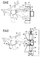
- a buffered Lead-in guide is installed, e.g., in correspondence of an entrance of a station, so to receive and guide cableway vehicles (not shown).
- the said vehicles are hung by a support element 11 extending from a hooking device 12 comprising a blocking clamp 13 for a cable 14, a device 15 for opening the said clamp, at Least one sliding wheel 29 and at Least one pivot 16 bearing at its end a rotary element 17, e.g., a wheel.
- a first wheel 17 enters the guide 10, while a second sliding wheel 29 comes above a guide and support track 18.
- the guide 10 having a "C"-shaped cross-section, and rearward constrained to a rigid beam 19, comprises an enlarged mouth section 20, which becomes gradually narrower, radiused towards a portion 21, the inner dimension of which is slightly greater than, and cLose to the dimension of wheel 17.
- the enlarged mouth portion 20 is arranged in a cantilevered position, and extends from the narrower portion 21 supported together with the rigid beam 19 inside at Least a first outer support 22 and a second outer support 23.
- the first outer support 22 is composed by at Least three beams 24 so welded and Linked to one another, as to form a housing for the guide portion 21 with the interposition of elastic elements 25 on both the sides thereof.
- the elastic elements 25 are constrained by screw bolts 26 both to the rigid beam 19 and to the beams 24 of the outer support 22, where they position themselves, adjustable in position, inside reLated threaded seats 27 provided on studs 28 which can be rotatably operated from the outside.
- the second outer support 23 is a simple section to which the rigid beam 19 is constrained, e.g., is hung, and in a particular form of practical embodiment it can be provided with a hinge for the same rigid beam 19, so to increase the positive effect of the elastic elements 25, allowing an articulation, even if of minimum extent, of the Lead-in guide 10.
- the elastic elements can be accomplished either by steel springs, or by pads of elastomeric material, so to be able to guarantee a good absorption of the impact as the wheel 17 enters the enlarged portion 20 of the guide 10, without however undergoing deformations, or, which is more important, without promoting the breakage or the damaging of the outer supports.
- the elastic elements can advantageously have also buffering properties, so to Limit, even if not to eliminate, the return forces of the guide 10, after that this Latter has received the bumps of the wheel of the cableway vehicle.
Landscapes
- Engineering & Computer Science (AREA)
- Transportation (AREA)
- Mechanical Engineering (AREA)
- Vibration Prevention Devices (AREA)
- Storage Of Web-Like Or Filamentary Materials (AREA)
- Electric Cable Installation (AREA)
- Vibration Dampers (AREA)
Applications Claiming Priority (2)
| Application Number | Priority Date | Filing Date | Title |
|---|---|---|---|
| IT2336685 | 1985-10-09 | ||
| IT2336685U IT206251Z2 (it) | 1985-10-09 | 1985-10-09 | Guida di invito ammortizzato per veicoli funiviari. |
Publications (2)
| Publication Number | Publication Date |
|---|---|
| EP0218306A2 true EP0218306A2 (de) | 1987-04-15 |
| EP0218306A3 EP0218306A3 (de) | 1987-08-05 |
Family
ID=11206454
Family Applications (1)
| Application Number | Title | Priority Date | Filing Date |
|---|---|---|---|
| EP86201733A Withdrawn EP0218306A3 (de) | 1985-10-09 | 1986-10-06 | Gedämpfte Stationseinführungsvorrichtung für Seilbahnfahrzeuge |
Country Status (4)
| Country | Link |
|---|---|
| EP (1) | EP0218306A3 (de) |
| DE (1) | DE8627335U1 (de) |
| FR (1) | FR2589117B3 (de) |
| IT (1) | IT206251Z2 (de) |
Cited By (11)
| Publication number | Priority date | Publication date | Assignee | Title |
|---|---|---|---|---|
| EP0640518A1 (de) * | 1993-08-25 | 1995-03-01 | Pomagalski S.A. | Stabilisierungsvorrichtung für die Klemmen einer Seilbahn |
| CN101351371B (zh) * | 2005-09-29 | 2011-01-12 | 高技术投资公司 | 用于缆车装置的承载/牵引缆绳的缆绳脱轨保护装置 |
| US8082853B2 (en) | 2003-01-30 | 2011-12-27 | High Technology Investments B.V. | Hold-down device for the cable guide in cable-drawn transport systems |
| US8393276B2 (en) | 2007-08-03 | 2013-03-12 | Rolic Invest S.Ar.L. | Cable transportation system and relative operating method |
| US8408141B2 (en) | 2007-10-26 | 2013-04-02 | Rolic Invest S.Ar.L. | Cable transportation system and relative operating method |
| US8474743B2 (en) | 2009-08-04 | 2013-07-02 | Rolic Invest S.Ar.L. | Ski-lift seat return device |
| US8573132B2 (en) | 2010-07-14 | 2013-11-05 | Rolic International S.Ar.L. | Cable transportation system switch and cable transportation system comprising such a switch |
| US8590458B2 (en) | 2007-04-20 | 2013-11-26 | Rolic Invest S.Ar.L. | Chair-lift |
| US8844446B2 (en) | 2007-04-20 | 2014-09-30 | Rolic International S.Ar.L. | Cable transportation system and relative drive method |
| US8991317B2 (en) | 2009-07-09 | 2015-03-31 | Rolic International S.A.R.L. | Transportation unit for cable transportation systems |
| AT526092A4 (de) * | 2022-06-30 | 2023-11-15 | Innova Patent Gmbh | Seilbahn mit Begrenzungsvorrichtung |
Family Cites Families (4)
| Publication number | Priority date | Publication date | Assignee | Title |
|---|---|---|---|---|
| DE134387C (de) * | ||||
| AT171834B (de) * | 1951-05-25 | 1952-07-10 | Leopold Girak | Gehängeführung für Seilbahnen |
| JPS5842060B2 (ja) * | 1979-02-05 | 1983-09-16 | 日産自動車株式会社 | 懸垂車両のロ−リング静定装置 |
| US4369714A (en) * | 1979-11-27 | 1983-01-25 | Nissan Motor Co., Ltd. | Cable car docking sway arrester mechanism |
-
1985
- 1985-10-09 IT IT2336685U patent/IT206251Z2/it active
-
1986
- 1986-10-06 EP EP86201733A patent/EP0218306A3/de not_active Withdrawn
- 1986-10-07 DE DE19868627335 patent/DE8627335U1/de not_active Expired
- 1986-10-09 FR FR8614051A patent/FR2589117B3/fr not_active Expired
Cited By (20)
| Publication number | Priority date | Publication date | Assignee | Title |
|---|---|---|---|---|
| EP0640518A1 (de) * | 1993-08-25 | 1995-03-01 | Pomagalski S.A. | Stabilisierungsvorrichtung für die Klemmen einer Seilbahn |
| FR2709278A1 (fr) * | 1993-08-25 | 1995-03-03 | Pomagalski Sa | Dispositif de stabilisation des pinces d'un téléporteur. |
| US5515789A (en) * | 1993-08-25 | 1996-05-14 | Pomagalski S.A. | Grip guiding device for aerial cableways |
| US8082853B2 (en) | 2003-01-30 | 2011-12-27 | High Technology Investments B.V. | Hold-down device for the cable guide in cable-drawn transport systems |
| CN101351371B (zh) * | 2005-09-29 | 2011-01-12 | 高技术投资公司 | 用于缆车装置的承载/牵引缆绳的缆绳脱轨保护装置 |
| US7891300B2 (en) | 2005-09-29 | 2011-02-22 | High Technology Investments B.V. | Cable derailing prevention device for carrier/traction cables of cable car systems |
| US9463811B2 (en) | 2007-04-20 | 2016-10-11 | Ropfin B.V. | Cable transportation system and relative drive method |
| US8590458B2 (en) | 2007-04-20 | 2013-11-26 | Rolic Invest S.Ar.L. | Chair-lift |
| US8844446B2 (en) | 2007-04-20 | 2014-09-30 | Rolic International S.Ar.L. | Cable transportation system and relative drive method |
| US9333876B2 (en) | 2007-08-03 | 2016-05-10 | Ropfin B.V. | Cable transportation system and relative operating method |
| US8534196B2 (en) | 2007-08-03 | 2013-09-17 | Rolic Invest S.Ar.L | Cable transportation system and relative operating method |
| US8393276B2 (en) | 2007-08-03 | 2013-03-12 | Rolic Invest S.Ar.L. | Cable transportation system and relative operating method |
| US8408141B2 (en) | 2007-10-26 | 2013-04-02 | Rolic Invest S.Ar.L. | Cable transportation system and relative operating method |
| US9738290B2 (en) | 2009-07-09 | 2017-08-22 | Ropfin B.V. | Transportation unit for cable transportation systems |
| US8991317B2 (en) | 2009-07-09 | 2015-03-31 | Rolic International S.A.R.L. | Transportation unit for cable transportation systems |
| US8474743B2 (en) | 2009-08-04 | 2013-07-02 | Rolic Invest S.Ar.L. | Ski-lift seat return device |
| US8573132B2 (en) | 2010-07-14 | 2013-11-05 | Rolic International S.Ar.L. | Cable transportation system switch and cable transportation system comprising such a switch |
| AT526092A4 (de) * | 2022-06-30 | 2023-11-15 | Innova Patent Gmbh | Seilbahn mit Begrenzungsvorrichtung |
| AT526092B1 (de) * | 2022-06-30 | 2023-11-15 | Innova Patent Gmbh | Seilbahn mit Begrenzungsvorrichtung |
| EP4299402A1 (de) * | 2022-06-30 | 2024-01-03 | Innova Patent GmbH | Seilbahn mit begrenzungsvorrichtung |
Also Published As
| Publication number | Publication date |
|---|---|
| IT8523366V0 (it) | 1985-10-09 |
| IT206251Z2 (it) | 1987-07-13 |
| DE8627335U1 (de) | 1987-01-08 |
| EP0218306A3 (de) | 1987-08-05 |
| FR2589117A3 (fr) | 1987-04-30 |
| FR2589117B3 (fr) | 1987-10-30 |
Similar Documents
| Publication | Publication Date | Title |
|---|---|---|
| EP0218306A2 (de) | Gedämpfte Stationseinführungsvorrichtung für Seilbahnfahrzeuge | |
| US3087583A (en) | Extended roller guide for elevators | |
| US3948188A (en) | Resilient railway bogie | |
| US4109586A (en) | Universally suspended snubbing railway axle truck | |
| US6345578B1 (en) | Double-acting trolley to support one-cable installations and in particular chair lifts and cabin lifts | |
| US5337997A (en) | Extruded aluminum spring hanger | |
| US3394662A (en) | Tracking truck | |
| US4870914A (en) | Diagonally braced railway truck | |
| US4612970A (en) | Guiding device for an oscillating continuous casting mold | |
| US5174219A (en) | Bogie for a track-guided vehicle | |
| FR2658471A1 (fr) | Bogie a pesee de charge pour vehicules de chemin de fer. | |
| US4429637A (en) | Railway vehicle truck | |
| US6035788A (en) | Bogie for rail vehicles | |
| US4785737A (en) | Buffered lead-in guide for cableway vehicles | |
| KR890001163B1 (ko) | 철도트럭 측부 프레임 사이에 연결된 가요성 트랜섬 | |
| US4331348A (en) | Vehicle suspension | |
| US4777886A (en) | Apparatus for supporting cables and transportation installation with aerial cables comprising an apparatus of this type | |
| US2934028A (en) | Railway vehicle structure | |
| US3762506A (en) | Railway vehicle disc brakes | |
| US2917005A (en) | Lightweight car truck | |
| SU1337297A1 (ru) | Транспортное устройство | |
| EP0097021B1 (de) | Kardenmaschinen | |
| RU218220U1 (ru) | Буксовый узел тележки грузового вагона с ограничителем, обеспечивающим возможность контроля за состоянием подшипника | |
| SU1744046A1 (ru) | Мостовой кран | |
| SU1310327A1 (ru) | Балансирна тележка транспортного средства |
Legal Events
| Date | Code | Title | Description |
|---|---|---|---|
| PUAI | Public reference made under article 153(3) epc to a published international application that has entered the european phase |
Free format text: ORIGINAL CODE: 0009012 |
|
| AK | Designated contracting states |
Kind code of ref document: A2 Designated state(s): AT BE CH DE FR GB LI LU NL SE |
|
| PUAL | Search report despatched |
Free format text: ORIGINAL CODE: 0009013 |
|
| RHK1 | Main classification (correction) |
Ipc: B61B 12/04 |
|
| AK | Designated contracting states |
Kind code of ref document: A3 Designated state(s): AT BE CH DE FR GB LI LU NL SE |
|
| 17P | Request for examination filed |
Effective date: 19880121 |
|
| 17Q | First examination report despatched |
Effective date: 19890414 |
|
| STAA | Information on the status of an ep patent application or granted ep patent |
Free format text: STATUS: THE APPLICATION IS DEEMED TO BE WITHDRAWN |
|
| 18D | Application deemed to be withdrawn |
Effective date: 19910212 |
|
| RIN1 | Information on inventor provided before grant (corrected) |
Inventor name: PABST, OTTO |