EP0218370B1 - Procédé et dispositif d'indication visuelle d'une relation entre deux signaux - Google Patents
Procédé et dispositif d'indication visuelle d'une relation entre deux signaux Download PDFInfo
- Publication number
- EP0218370B1 EP0218370B1 EP86306838A EP86306838A EP0218370B1 EP 0218370 B1 EP0218370 B1 EP 0218370B1 EP 86306838 A EP86306838 A EP 86306838A EP 86306838 A EP86306838 A EP 86306838A EP 0218370 B1 EP0218370 B1 EP 0218370B1
- Authority
- EP
- European Patent Office
- Prior art keywords
- signal
- vectorscope
- signals
- terminal
- waves
- Prior art date
- Legal status (The legal status is an assumption and is not a legal conclusion. Google has not performed a legal analysis and makes no representation as to the accuracy of the status listed.)
- Expired
Links
Images
Classifications
-
- H—ELECTRICITY
- H04—ELECTRIC COMMUNICATION TECHNIQUE
- H04S—STEREOPHONIC SYSTEMS
- H04S7/00—Indicating arrangements; Control arrangements, e.g. balance control
- H04S7/40—Visual indication of stereophonic sound image
Definitions
- This invention relates to a method and apparatus for providing a visual indication of a relationship between two signals.
- the video vectorscope (as is described for example in EP-A-0 130 717) is an instrument that is widely used for evaluation of a composite color television signal.
- the term "vectorscope” means an instrument having an input terminal.
- a display surface means for generating a visible dot on the display surface, X and Y deflection means for deflecting the position of the visible dot in mutually perpendicular rectilinear directions, a wave regenerator for generating a continuous wave signal at a predetermined operating frequency, first and second demodulators having their outputs connected to the X and Y deflection means respectively and e.ach having first and second inputs, means connecting the output of the wave regenerator to the first inputs of the first and second demodulators with a quarter-period relative phase difference, and a filter which passes signal components at the operating frequency of the wave regenerator and is connected between the input terminal of the vectorscope and the second inputs of the first and second demodulators.
- video veclorscope means a vectorscope in which the operating frequency is the color subcarrier frequency.
- a composite color video signal contains timing information and information representative of the distribution of color over a scene.
- the scene may be a natural scene, imaged on the image-receiving surface of a video camera, or it may be an artificial scene, such as might be created using a video graphics unit or a test signal generator.
- the signal when used to drive a video display unit, causes the video display unit to create an image that conveys intelligible information through the visual sense.
- a signal is "representative of a variable other than the distribution of color over a scene” if, when used to drive a video display unit, it does not cause the display unit to create an image that conveys intelligible information through the visual sense.
- An image conveys intelligible information through the visual sense if it contains not only information representative of color difference but also information representative of perceptible structure.
- a videotape recorder VTR
- the vectorscope is used to determine whether the color information of a composite color television signal being processed by the VTR is properly encoded, so that upon playback the color information can be recovered using a standard display.
- a VTR is used to record not only visual information but also audio information.
- an audio signal is transmitted about a television studio in balanced form using a two-conductor cable.
- the relative polarities of the two conductors that carry the balanced audio signal are unimportant. Consequently, in the case of a monaural audio system it is not necessary to pay attention to the polarities of the two conductors, and many of the connectors used for connecting the two-conductor cables are not polarized.
- An X-Y oscilloscope may be used to determine whether two periodic signals are in phase, by connecting the two signals to the two deflection amplifiers respectively and observing the shape of the display that is obtained. If the two signals are pure sine waves, the display will be a Lissajous figure, and its shape will depend on the phase and frequency relationships between the two signals. If the signals are the same frequency, the Lissajous figure will be an ellipse having a major axis extending diagonally across the screen of the CRT from its lower left corner to its upper right corner if the signals are in phase. If the signals are out of phase, the major axis of the ellipse will be disposed along the other diagonal of the CRT screen.
- a visual indication of the relationship between first and second electrical signals is provided through use of a video vectorscope.
- the first and second signals are used to modulate the amplitude of two sinusoidal waves at subcarrier frequency and in phase quadrature, so as to synthesize the chrominance portion of a composite video signal.
- the two modulated sine waves are additively combined, and the resulting signal is applied to the input terminal of the vectorscope.
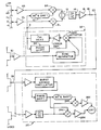
- the apparatus illustrated in the figure comprises two input terminals 2L and 2R that are connected to receive left and right channel singleended audio signals.
- each terminal would receive its audio signal from a two-conductor audio cable by way of a differential amplifier which converts the balanced audio signals on the two-conductor cable to a single-ended form.
- the two terminals 2L and 2R are connected through potentiometers 4L and 4R to respective amplifiers 6L and 6R.
- the amplifiers 6L and 6R serve to buffer the input terminals and limit the maximum bandwidth of the signals to a maximum frequency of 1 - 2 MHz to protect the modulation process which follows.
- the outputs of the amplifiers 6L, 6R are connected to respective two double-balanced mixers 8L, 8R.
- Each mixer has a second input terminal at which it receives a signal at subcarrier frequency (3.58 MHz In the case of the NTSC system).
- the two signals at subcarrier frequency are in phase quadrature by virtue of their originating from a common terminal 9 and there being a 90 degree phase shifter 10 connected between the terminal 9 and the mixer 8R.
- the outputs of the two mixers 8L and 8R are combined in a summer 12, and the output of the summer is connected to a bandpass filter 14 having a center frequency at subcarrier frequency and having a bandwidth of about 2 MHz.
- the output of the filter 14 is connected through a video amplifier 16 and an impedance matching resistor 18 to an output terminal 20.
- the output terminal 20 is connected to the A/B signal input of a conventional vectorscope 22.
- the demodulators 24 of the vectorscope will separate the left and right channel audio signals and apply them to the Y and X deflection amplifiers 26Y and 26X respectively, and accordingly the vectorscope will provide a display of the relative magnitudes of the left and right channel audio signals. Since the typical vectorscope has a bandwidth of up to about 600 kHz, the display yields information regarding the instantaneous relative magnitudes of the left and right channel signals, and not just the long term relative magnitudes, as would be provided by VU meters.
- the display on the screen of the vectorscope is a relatively narrow illuminated band. If the subcarrier frequency signal used to generate the signal applied to the input terminal of the vectorscope is in phase with the subcarrier frequency signal against which the signal is demodulated, the band is oriented along the diagonal from the lower left corner of the vectorscope screen to its upper right corner if the left and right audio signals are in phase and is oriented along the other diagonal if the left and right audio signals are out of phase.
- the present invention provides the advantage of being able to provide an X - Y display of two signals using a vectorscope, which has only one signal input terminal.
- the subcarrier frequency signal that is applied to the mixers 8 may be a continuous wave subcarrier from a master subcarrier generator, or it may be a regenerateed CW signal locked to a black burst composite video signal.
- the subcarrier frequency signal is applied to the reference input 28 of the vectorscope and to a terminal 30 which is connected to the terminal 9 either directly or through a subcarrier regenerator 32.
- the subcarrier regenerator is of conventional form and provides at the terminal 9 a continuous wave signal at subcarrier frequency and adjustable in phase relative to the signal applied to the terminal 30.
- the phase shifter 34 of the subcarrier regenerator makes it possible to cancel the effects of differential time delays in the cables between the vectorscope 22 and the terminals 20 and 30. Moreover, the phase shifter 34 makes it possible, at a given setting of the phase shifter of the vectorscope, to property orient the display provided by the signal at the terminal 20 so as to not require readjustment of the phase shifter of the vectorscope.
Landscapes
- Physics & Mathematics (AREA)
- Engineering & Computer Science (AREA)
- Acoustics & Sound (AREA)
- Signal Processing (AREA)
- Stereophonic System (AREA)
- Testing, Inspecting, Measuring Of Stereoscopic Televisions And Televisions (AREA)
Claims (7)
Applications Claiming Priority (2)
| Application Number | Priority Date | Filing Date | Title |
|---|---|---|---|
| US774781 | 1985-09-11 | ||
| US06/774,781 US4648113A (en) | 1985-09-11 | 1985-09-11 | Method and apparatus for providing a visual indication of a relationship between two signals |
Publications (2)
| Publication Number | Publication Date |
|---|---|
| EP0218370A1 EP0218370A1 (fr) | 1987-04-15 |
| EP0218370B1 true EP0218370B1 (fr) | 1990-02-28 |
Family
ID=25102282
Family Applications (1)
| Application Number | Title | Priority Date | Filing Date |
|---|---|---|---|
| EP86306838A Expired EP0218370B1 (fr) | 1985-09-11 | 1986-09-04 | Procédé et dispositif d'indication visuelle d'une relation entre deux signaux |
Country Status (7)
| Country | Link |
|---|---|
| US (1) | US4648113A (fr) |
| EP (1) | EP0218370B1 (fr) |
| JP (1) | JP2520236B2 (fr) |
| AU (1) | AU582072B2 (fr) |
| CA (1) | CA1251876A (fr) |
| DE (1) | DE3669251D1 (fr) |
| DK (1) | DK165208C (fr) |
Families Citing this family (20)
| Publication number | Priority date | Publication date | Assignee | Title |
|---|---|---|---|---|
| CA1270523A (fr) * | 1987-03-27 | 1990-06-19 | Bertrand Bouchard | Identificateur de phases |
| US5048390A (en) * | 1987-09-03 | 1991-09-17 | Yamaha Corporation | Tone visualizing apparatus |
| JP2524795B2 (ja) * | 1988-02-12 | 1996-08-14 | パイオニア株式会社 | ディスク再生装置 |
| GB8820778D0 (en) * | 1988-09-02 | 1988-10-05 | Renishaw Plc | Setting up of quadrature signals |
| US4908868A (en) * | 1989-02-21 | 1990-03-13 | Mctaggart James E | Phase polarity test instrument and method |
| GB8905686D0 (en) * | 1989-03-13 | 1989-04-26 | Stelling David | Stereo signal monitoring |
| JP3497234B2 (ja) * | 1994-05-17 | 2004-02-16 | リーダー電子株式会社 | ベクトルスコープ用の移相装置 |
| DE19642199A1 (de) * | 1996-10-12 | 1998-04-16 | Heidenhain Gmbh Dr Johannes | Kontrollvorrichtung und Verfahren zur Prüfung von positionsabhängigen Abtastsignalen |
| GB2319346B (en) * | 1996-11-13 | 2001-03-21 | Sony Uk Ltd | Analysis of audio signals |
| US6144762A (en) * | 1998-02-23 | 2000-11-07 | Olympus America Inc. | Stereo video microscope |
| CA2395156A1 (fr) | 1999-12-20 | 2001-06-28 | Henry Moncrieff O'connor | Procede permettant de produire et d'afficher des donnees complexes a l'aide de signaux a code de couleur |
| US7039201B1 (en) * | 2000-10-31 | 2006-05-02 | Leetronics Corporation | Audio signal phase detection system and method |
| JP4571381B2 (ja) * | 2003-06-30 | 2010-10-27 | リーダー電子株式会社 | ベクトル波形回転装置 |
| US8624602B2 (en) * | 2005-09-27 | 2014-01-07 | Ronald Quan | Method and apparatus to measure differential phase and frequency modulation distortions for audio equipment |
| US9271097B2 (en) | 2013-05-31 | 2016-02-23 | Ronald Quan | Method and apparatus to evaluate audio equipment via filter banks |
| US9729987B2 (en) | 2005-09-27 | 2017-08-08 | Ronald Quan | Method and apparatus to evaluate audio equipment via at least one filter for dynamic distortions and or differential phase and or frequency modulation effects |
| US9386385B2 (en) | 2005-09-27 | 2016-07-05 | Ronald Quan | Method and apparatus to evaluate audio equipment via filter banks for dynamic distortions and or differential phase and frequency modulation effects |
| US8704533B2 (en) * | 2005-09-27 | 2014-04-22 | Ronald Quan | Method and apparatus to measure differential phase and frequency modulation distortions for audio equipment |
| US9307227B2 (en) * | 2011-02-24 | 2016-04-05 | Tektronix, Inc. | Stereoscopic image registration and color balance evaluation display |
| US9301046B1 (en) * | 2013-09-27 | 2016-03-29 | Cirrus Logic, Inc. | Systems and methods for minimizing distortion in an audio output stage |
Family Cites Families (24)
| Publication number | Priority date | Publication date | Assignee | Title |
|---|---|---|---|---|
| US2500646A (en) * | 1946-11-23 | 1950-03-14 | Bell Telephone Labor Inc | Visual representation of complex waves |
| US2986700A (en) * | 1958-04-23 | 1961-05-30 | Gen Electric | Testing and measuring circuit |
| FR1604103A (fr) * | 1958-11-07 | 1971-07-12 | ||
| US3039054A (en) * | 1958-11-26 | 1962-06-12 | Gen Electric Co Ltd | Apparatus for measuring the frequency of electric waves |
| US3067297A (en) * | 1960-02-26 | 1962-12-04 | Philco Corp | Apparatus for determining the polarities of stereophonic channel connections at anyselected point |
| US3534155A (en) * | 1967-10-05 | 1970-10-13 | Tektronix Inc | Measurement of characteristic of electrical signal by positioning measured portions of a corresponding pair of opposite phase signals in coincidence |
| US3627912A (en) * | 1969-04-23 | 1971-12-14 | William E Hearn | Visual display of complex color television sound wave signals |
| JPS5533240B1 (fr) * | 1971-06-22 | 1980-08-29 | ||
| US3856985A (en) * | 1973-05-17 | 1974-12-24 | Tokyo Shibaura Electric Co | Ultrasonic diagnostic apparatus |
| US3940789A (en) * | 1973-07-13 | 1976-02-24 | Kew, Incorporated | Multicolor display for the visual-aesthetic portrayal of electric signals |
| US3876936A (en) * | 1973-09-17 | 1975-04-08 | Motorola Inc | Visual audio frequency comparator |
| US4135203A (en) * | 1974-08-20 | 1979-01-16 | Friedman Alan M | Method and apparatus for generating complex visual patterns |
| US3969972A (en) * | 1975-04-02 | 1976-07-20 | Bryant Robert L | Music activated chromatic roulette generator |
| US4081829A (en) * | 1976-08-23 | 1978-03-28 | Atari, Inc. | Audio activated video display |
| US4128846A (en) * | 1977-05-02 | 1978-12-05 | Denis J. Kracker | Production of modulation signals from audio frequency sources to control color contributions to visual displays |
| US4167752A (en) * | 1977-10-03 | 1979-09-11 | Liebler Jerome E | Color video display for audio signals |
| US4267561A (en) * | 1977-11-02 | 1981-05-12 | Karpinsky John R | Color video display for audio signals |
| US4195310A (en) * | 1978-07-12 | 1980-03-25 | Phastek | Kinescope drive system for displaying audio signals |
| US4237482A (en) * | 1978-12-01 | 1980-12-02 | Brentlinger Brent R | Display system for achieving aesthetically pleasing lissajous patterns from a single source of signals |
| US4257062A (en) * | 1978-12-29 | 1981-03-17 | Meredith Russell W | Personalized audio-visual system |
| US4406922A (en) * | 1980-05-19 | 1983-09-27 | Motorola Inc. | Stereo broadcast system |
| JPS57160292A (en) * | 1981-03-27 | 1982-10-02 | Reader Denshi Kk | Vectorscope |
| US4470064A (en) * | 1982-03-31 | 1984-09-04 | The Grass Valley Group, Inc. | Horizontal sync to subcarrier phase measurement method and apparatus |
| JPS6010177A (ja) * | 1983-06-15 | 1985-01-19 | テクトロニツクス・インコーポレイテツド | 信号位相及び振幅表示装置 |
-
1985
- 1985-09-11 US US06/774,781 patent/US4648113A/en not_active Expired - Lifetime
-
1986
- 1986-07-29 CA CA000514860A patent/CA1251876A/fr not_active Expired
- 1986-09-04 DE DE8686306838T patent/DE3669251D1/de not_active Expired - Fee Related
- 1986-09-04 EP EP86306838A patent/EP0218370B1/fr not_active Expired
- 1986-09-10 AU AU62567/86A patent/AU582072B2/en not_active Ceased
- 1986-09-10 JP JP61213723A patent/JP2520236B2/ja not_active Expired - Fee Related
- 1986-09-10 DK DK432186A patent/DK165208C/da not_active IP Right Cessation
Also Published As
| Publication number | Publication date |
|---|---|
| DK165208B (da) | 1992-10-19 |
| US4648113A (en) | 1987-03-03 |
| AU6256786A (en) | 1987-03-12 |
| EP0218370A1 (fr) | 1987-04-15 |
| DK432186D0 (da) | 1986-09-10 |
| JPS6262693A (ja) | 1987-03-19 |
| CA1251876A (fr) | 1989-03-28 |
| DE3669251D1 (de) | 1990-04-05 |
| AU582072B2 (en) | 1989-03-09 |
| JP2520236B2 (ja) | 1996-07-31 |
| DK432186A (da) | 1987-03-12 |
| DK165208C (da) | 1993-03-15 |
Similar Documents
| Publication | Publication Date | Title |
|---|---|---|
| US4648113A (en) | Method and apparatus for providing a visual indication of a relationship between two signals | |
| US3849594A (en) | Multi-picture tv system with audio and doding channels | |
| US5388159A (en) | Equalizing circuit for reproduced signals | |
| KR890001906B1 (ko) | 비데오신호 중첩장치 | |
| JP2785337B2 (ja) | 磁気記録再生装置 | |
| JPS59225684A (ja) | ビデオテキスト信号の記録部を有するビデオレコ−ダ | |
| US4123774A (en) | Color signal encoding methods and apparatus for video recording and playback | |
| GB1322041A (en) | Transducer system and method | |
| US4296431A (en) | High-resolution television system | |
| US4266241A (en) | Color signal encoding methods and apparatus for video recording and playback | |
| US2898397A (en) | Color-television system | |
| US4821087A (en) | Encoder circuit eliminating carrier leak | |
| US3908193A (en) | Color television encoding and decoding system | |
| US4694324A (en) | Measurement of SC/H phase using a polar display | |
| US5053882A (en) | Video signal optical transmission system | |
| CA1250043A (fr) | Mesure au moyen d'un vecteurscope de la phase entre la sous-porteuse et le signal de synchronisation horizontale dans un signal video | |
| US2811577A (en) | Color television system | |
| Basile | Channel matching techniques for 2-channel television | |
| JPH0448065Y2 (fr) | ||
| CA1256196A (fr) | Mesure de la phase entre le sous-porteuse et de signal de synchronisation horizontale au moyen d'un affichage polaire | |
| JPS63198497A (ja) | カラ−エンコ−ダ | |
| KR900005187B1 (ko) | 수직윤곽 보정장치 | |
| JPS63210786A (ja) | 測定装置 | |
| JPS62236294A (ja) | 3次元画像信号記録装置 | |
| JPH02140081A (ja) | 映像信号記録装置 |
Legal Events
| Date | Code | Title | Description |
|---|---|---|---|
| PUAI | Public reference made under article 153(3) epc to a published international application that has entered the european phase |
Free format text: ORIGINAL CODE: 0009012 |
|
| AK | Designated contracting states |
Kind code of ref document: A1 Designated state(s): DE FR GB NL |
|
| 17P | Request for examination filed |
Effective date: 19870424 |
|
| 17Q | First examination report despatched |
Effective date: 19881208 |
|
| GRAA | (expected) grant |
Free format text: ORIGINAL CODE: 0009210 |
|
| AK | Designated contracting states |
Kind code of ref document: B1 Designated state(s): DE FR GB NL |
|
| ET | Fr: translation filed | ||
| REF | Corresponds to: |
Ref document number: 3669251 Country of ref document: DE Date of ref document: 19900405 |
|
| PLBE | No opposition filed within time limit |
Free format text: ORIGINAL CODE: 0009261 |
|
| STAA | Information on the status of an ep patent application or granted ep patent |
Free format text: STATUS: NO OPPOSITION FILED WITHIN TIME LIMIT |
|
| 26N | No opposition filed | ||
| PGFP | Annual fee paid to national office [announced via postgrant information from national office to epo] |
Ref country code: FR Payment date: 19920807 Year of fee payment: 7 |
|
| PGFP | Annual fee paid to national office [announced via postgrant information from national office to epo] |
Ref country code: NL Payment date: 19920930 Year of fee payment: 7 |
|
| PG25 | Lapsed in a contracting state [announced via postgrant information from national office to epo] |
Ref country code: NL Effective date: 19940401 |
|
| NLV4 | Nl: lapsed or anulled due to non-payment of the annual fee | ||
| PG25 | Lapsed in a contracting state [announced via postgrant information from national office to epo] |
Ref country code: FR Free format text: LAPSE BECAUSE OF NON-PAYMENT OF DUE FEES Effective date: 19940531 |
|
| REG | Reference to a national code |
Ref country code: FR Ref legal event code: ST |
|
| PGFP | Annual fee paid to national office [announced via postgrant information from national office to epo] |
Ref country code: DE Payment date: 19980826 Year of fee payment: 13 |
|
| PG25 | Lapsed in a contracting state [announced via postgrant information from national office to epo] |
Ref country code: DE Free format text: LAPSE BECAUSE OF NON-PAYMENT OF DUE FEES Effective date: 20000701 |
|
| REG | Reference to a national code |
Ref country code: GB Ref legal event code: IF02 |
|
| PGFP | Annual fee paid to national office [announced via postgrant information from national office to epo] |
Ref country code: GB Payment date: 20020815 Year of fee payment: 17 |
|
| PG25 | Lapsed in a contracting state [announced via postgrant information from national office to epo] |
Ref country code: GB Free format text: LAPSE BECAUSE OF NON-PAYMENT OF DUE FEES Effective date: 20030904 |
|
| GBPC | Gb: european patent ceased through non-payment of renewal fee |