EP0218394A2 - Dichtung für Flüssigkeiten - Google Patents
Dichtung für Flüssigkeiten Download PDFInfo
- Publication number
- EP0218394A2 EP0218394A2 EP86307143A EP86307143A EP0218394A2 EP 0218394 A2 EP0218394 A2 EP 0218394A2 EP 86307143 A EP86307143 A EP 86307143A EP 86307143 A EP86307143 A EP 86307143A EP 0218394 A2 EP0218394 A2 EP 0218394A2
- Authority
- EP
- European Patent Office
- Prior art keywords
- fluid seal
- loading means
- loading
- sealing lip
- seal
- Prior art date
- Legal status (The legal status is an assumption and is not a legal conclusion. Google has not performed a legal analysis and makes no representation as to the accuracy of the status listed.)
- Withdrawn
Links
Images
Classifications
-
- F—MECHANICAL ENGINEERING; LIGHTING; HEATING; WEAPONS; BLASTING
- F16—ENGINEERING ELEMENTS AND UNITS; GENERAL MEASURES FOR PRODUCING AND MAINTAINING EFFECTIVE FUNCTIONING OF MACHINES OR INSTALLATIONS; THERMAL INSULATION IN GENERAL
- F16J—PISTONS; CYLINDERS; SEALINGS
- F16J15/00—Sealings
- F16J15/16—Sealings between relatively-moving surfaces
- F16J15/32—Sealings between relatively-moving surfaces with elastic sealings, e.g. O-rings
- F16J15/3204—Sealings between relatively-moving surfaces with elastic sealings, e.g. O-rings with at least one lip
- F16J15/3208—Sealings between relatively-moving surfaces with elastic sealings, e.g. O-rings with at least one lip provided with tension elements, e.g. elastic rings
Definitions
- the invention concerns fluid seals, and has particular, though not exclusive reference to oil seals wherein the sealing element comprises a thin shell of polytetrafluorethylene (P.T.F.E.).
- Oil seals are known wherein the PTFE sealing element is directly loaded by a garter spring, such an arrangement being shown in our prior U.K. Patent No. 2096246.
- the object of the present invention is to provide an alternative to the garter spring aforesaid as a means for loading the sealing element.
- a fluid seal comprising a housing, a flexible sealing element seated in said housing and presenting a sealing lip extending in the axial direction of the seal, and a resilient loading means captively located in the housing under conditions of axial pressure, the loading means extending between the back of the sealing lip and a reaction surface arranged in opposed disposition relative thereto and the axial pressure applied to the loading means giving rise to a radial loading of the sealing element.
- the loading means includes spaced parallel ribs in contact with the reaction surface and/or the sealing lip and through which pressure is applied to the sealing lip.
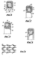
- a fluid seal comprises an annular casing 11 of generally L-shaped transverse cross-section, a moulded, annular P.T.F.E. sealing element 12 of channel section seated in said casing, the channel section being open in the axial direction of the seal, a resilient loading ring 13 positioned within the sealing element 12 to exert a sealing pressure on the radially inner shaft engaging limb 14 of the sealing element, and a retaining washer 15 abutting a side face 16 of the loading ring 13, the edge of the casing 11 being pressed radially inwardly, at 17, to overlie the outer peripheral edge of the retaining washer 15 and thus hold the sealing element 12, loading ring 13 and washer 15 in captive engagement with the casing 11.
- the sealing element 12 comprises a thin annulus of a P.T.F.E. material, having a typical thickness of between 0.5 and 1.0 mm, moulded to the channel-shaped form illustrated in the drawing, the radially outer limb of the U-shaped element being of a lesser dimension than the essentially parallel, inner rim, and being dimensioned to be in close fit in the casing in the closed condition thereof.
- the loading ring 13 is of comparable form to the elastomeric sealing ring disclosed in U.K. Patent Specification No. 1148885, and the dimension thereof in relation to the dimensions of the casing 11 are such as to give rise to a compression of the loading ring 13 in the axial direction of the seal on securing of the washer 15 relative to the casing, and a consequential loading of the P.T.F.E. sealing element radially inwardly of the seal.
- the loading ring 13 is thus of basically square cross-section and has chamfered corners 18, the two opposite radial faces 19 of the ring and the two opposite axial faces 20 having arcuate recesses therein, thus defining respective pairs of lips, at the radially inner and outer peripheries of the ring.
- That axial compression of the loading ring 13 which arises on assembly of the seal gives rise to a radial loading of the sealing element 12 along the respective lines of contact of the radially inner lips 21 of the loading ring 13 and the back of the sealing portion 14 of the sealing element 12, the radially outer lips being in contact with the casing which thus provides a reaction surface for the sealing forces involved.
- Fig. 2 differs from that of Fig. 1 only as regards the presence of a washer of angle section the radially outer limb of the sealing element engaging the cylindrical inner face 26 of the washer and providing for relative rotational movement between the sealing element 12, on the one hand, and both the shaft and housing (as representated by the casing) on the other.
- seals analogous to those shown in Figs. 1 and 2 may be provided for application to a fixed shaft, those illustrated being intended for use in the context of rotary shafts.
- such means may comprise a ribbon of a tubular knitted fabric arranged in flattened form, the ribbon being folded about its longitudinal axis, to give a transverse cross-section of generally U-shape and the ends of the ribbon being brought into abutment to give a loop for location within a seal casing in analogous manner to the elastimeric loading means of the previous embodiments.
- Fig. 5 is a scrap view of the flattened circular knit fabric.
- the loading means 33 is disposed within the casing 30 with the parallel limbs 35, 36 thereof directed towards and engaged with the rear face 37 of the sealing part 38 of the sealing element 39, such loading means thus applying pressure to the sealing element along two spaced parallel lines.
- the loading means 43 is oppositely directed relative to the sealing element 44, and engages such element along a single line (or band), rather than at the spaced locations of the embodiment shown in Fig. 3.
- the knitted fabric which fabric is disclosed in U.K. Patent Application No. 8523893 is of stainless steel wire, the interlocking loops of the fabric providing an even radial loading to the sealing element throughout the full peripheral extent of the contact between the fabric and sealing element and acting as a multiplicity of minute individual springs capable of accommodating displacements arising from shaft deflections.
- seals as aforesaid are of application in the context of rotational or reciprocatory motion, or a combination thereof.
Landscapes
- Engineering & Computer Science (AREA)
- General Engineering & Computer Science (AREA)
- Mechanical Engineering (AREA)
- Sealing Devices (AREA)
- Gasket Seals (AREA)
- Sealing With Elastic Sealing Lips (AREA)
Applications Claiming Priority (2)
| Application Number | Priority Date | Filing Date | Title |
|---|---|---|---|
| GB8523892 | 1985-09-27 | ||
| GB858523892A GB8523892D0 (en) | 1985-09-27 | 1985-09-27 | Fluid seals |
Publications (2)
| Publication Number | Publication Date |
|---|---|
| EP0218394A2 true EP0218394A2 (de) | 1987-04-15 |
| EP0218394A3 EP0218394A3 (de) | 1988-04-27 |
Family
ID=10585831
Family Applications (1)
| Application Number | Title | Priority Date | Filing Date |
|---|---|---|---|
| EP86307143A Withdrawn EP0218394A3 (de) | 1985-09-27 | 1986-09-17 | Dichtung für Flüssigkeiten |
Country Status (3)
| Country | Link |
|---|---|
| EP (1) | EP0218394A3 (de) |
| JP (1) | JPS6275176A (de) |
| GB (2) | GB8523892D0 (de) |
Cited By (4)
| Publication number | Priority date | Publication date | Assignee | Title |
|---|---|---|---|---|
| US6106847A (en) * | 1996-09-13 | 2000-08-22 | Lancaster Group Gmbh | Stable multiple phase emulsion of the type O1 /W/O2 |
| EP2618032A3 (de) * | 2012-01-19 | 2014-01-29 | Kaco GmbH & Co. KG | Wellendichtung, insbesondere Radialwellendichtung |
| EP3120052A4 (de) * | 2014-03-21 | 2017-11-29 | Saint-Gobain Performance Plastics Corporation | Rotierende wellendichtung |
| EP3842671B1 (de) * | 2019-12-23 | 2024-05-15 | KACO GmbH + Co. KG | Wellendichtung, insbesondere radialwellendichtung, mit wenigstens einem dichtelement |
Families Citing this family (5)
| Publication number | Priority date | Publication date | Assignee | Title |
|---|---|---|---|---|
| DE3821893A1 (de) * | 1987-10-07 | 1989-04-27 | Josef Nemetz | Dichtungsring mit fuehrung |
| GB8724015D0 (en) * | 1987-10-13 | 1987-11-18 | Fenner Co Ltd J H | Fluid seals |
| DE3903386C2 (de) * | 1988-06-29 | 1995-05-04 | Josef Nemetz | Dichtungsring mit Führung |
| DE4243417A1 (de) * | 1992-09-01 | 1994-03-24 | Daetwyler Ag | Dichtungsring |
| US9512934B2 (en) * | 2013-06-18 | 2016-12-06 | Fisher Controls International Llc | Seal assemblies for use with fluid valves |
Family Cites Families (3)
| Publication number | Priority date | Publication date | Assignee | Title |
|---|---|---|---|---|
| FR557823A (fr) * | 1922-10-25 | 1923-08-16 | Perfectionnement aux presse étoupes | |
| DE3026063A1 (de) * | 1980-07-10 | 1982-02-04 | Busak + Luyken GmbH & Co, 7000 Stuttgart | Dichtung fuer hydraulische kolben und kolbenstangen |
| GB8325427D0 (en) * | 1983-09-22 | 1983-10-26 | Fenner Co Ltd J H | Lip seals |
-
1985
- 1985-09-27 GB GB858523892A patent/GB8523892D0/en active Pending
-
1986
- 1986-09-17 EP EP86307143A patent/EP0218394A3/de not_active Withdrawn
- 1986-09-17 GB GB08622424A patent/GB2181191B/en not_active Expired
- 1986-09-25 JP JP61225054A patent/JPS6275176A/ja active Pending
Cited By (7)
| Publication number | Priority date | Publication date | Assignee | Title |
|---|---|---|---|---|
| US6106847A (en) * | 1996-09-13 | 2000-08-22 | Lancaster Group Gmbh | Stable multiple phase emulsion of the type O1 /W/O2 |
| EP2618032A3 (de) * | 2012-01-19 | 2014-01-29 | Kaco GmbH & Co. KG | Wellendichtung, insbesondere Radialwellendichtung |
| US9869393B2 (en) | 2012-01-19 | 2018-01-16 | Kaco Gmbh + Co. Kg | Shaft seal, especially radial shaft seal |
| EP3120052A4 (de) * | 2014-03-21 | 2017-11-29 | Saint-Gobain Performance Plastics Corporation | Rotierende wellendichtung |
| KR20190089224A (ko) * | 2014-03-21 | 2019-07-30 | 생-고뱅 퍼포먼스 플라스틱스 코포레이션 | 회전축 시일 |
| EP3865739A1 (de) * | 2014-03-21 | 2021-08-18 | Saint-Gobain Performance Plastics Corporation | Rotierende wellendichtung |
| EP3842671B1 (de) * | 2019-12-23 | 2024-05-15 | KACO GmbH + Co. KG | Wellendichtung, insbesondere radialwellendichtung, mit wenigstens einem dichtelement |
Also Published As
| Publication number | Publication date |
|---|---|
| EP0218394A3 (de) | 1988-04-27 |
| JPS6275176A (ja) | 1987-04-07 |
| GB8622424D0 (en) | 1986-10-22 |
| GB8523892D0 (en) | 1985-10-30 |
| GB2181191B (en) | 1988-08-24 |
| GB2181191A (en) | 1987-04-15 |
Similar Documents
| Publication | Publication Date | Title |
|---|---|---|
| CA1333918C (en) | Shaft seal | |
| US5599026A (en) | Turbine seal with sealing strip and rubbing strip | |
| US2743950A (en) | Shaft seal | |
| US6409177B1 (en) | Rotary shaft seal | |
| EP0568192A1 (de) | Sekundärdichtung für Gasturbine | |
| US4844485A (en) | Lip seal assembly for a rotatable shaft | |
| EP0351549B1 (de) | Federgespannter Führungsring | |
| GB2137702A (en) | Combination wear sleeve and excluder lip adapted for easy installation | |
| EP0184285B1 (de) | Ringdichtung | |
| EP0798499A1 (de) | Gleitringdichtung | |
| GB2258276A (en) | Seal ring | |
| JPS6165966A (ja) | リングシール | |
| JP4704428B2 (ja) | 複合ロータリーシールアセンブリ | |
| US4971337A (en) | Mechanical seal assembly | |
| GB1517895A (en) | Annular seals | |
| CA1244851A (en) | High pressure shaft seal | |
| US3588126A (en) | Unit-type packing seal for shaft | |
| EP0004982B1 (de) | Rotierender Balg mit Schwingungsdämpfung | |
| US5213342A (en) | Lip seal with radially compressible support band | |
| US5605338A (en) | Liquid pump seal | |
| US5653449A (en) | Seal assembly | |
| GB2181191A (en) | Fluid seals | |
| EP0230738A2 (de) | Abdichtung für Wellen und dergleichen | |
| US3367666A (en) | Seal | |
| US3449021A (en) | Low friction resilient sealing ring |
Legal Events
| Date | Code | Title | Description |
|---|---|---|---|
| PUAI | Public reference made under article 153(3) epc to a published international application that has entered the european phase |
Free format text: ORIGINAL CODE: 0009012 |
|
| AK | Designated contracting states |
Kind code of ref document: A2 Designated state(s): AT BE CH DE FR IT LI NL SE |
|
| PUAL | Search report despatched |
Free format text: ORIGINAL CODE: 0009013 |
|
| AK | Designated contracting states |
Kind code of ref document: A3 Designated state(s): AT BE CH DE FR IT LI NL SE |
|
| STAA | Information on the status of an ep patent application or granted ep patent |
Free format text: STATUS: THE APPLICATION IS DEEMED TO BE WITHDRAWN |
|
| 18D | Application deemed to be withdrawn |
Effective date: 19881028 |
|
| RIN1 | Information on inventor provided before grant (corrected) |
Inventor name: POTTER, CHARLES WILLIAM |