EP0218405A2 - Appareil pour compenser le poids dynamique - Google Patents
Appareil pour compenser le poids dynamique Download PDFInfo
- Publication number
- EP0218405A2 EP0218405A2 EP86307268A EP86307268A EP0218405A2 EP 0218405 A2 EP0218405 A2 EP 0218405A2 EP 86307268 A EP86307268 A EP 86307268A EP 86307268 A EP86307268 A EP 86307268A EP 0218405 A2 EP0218405 A2 EP 0218405A2
- Authority
- EP
- European Patent Office
- Prior art keywords
- platform
- members
- base
- derrick
- cylinders
- Prior art date
- Legal status (The legal status is an assumption and is not a legal conclusion. Google has not performed a legal analysis and makes no representation as to the accuracy of the status listed.)
- Withdrawn
Links
- 238000006073 displacement reaction Methods 0.000 claims abstract description 14
- 230000033001 locomotion Effects 0.000 claims description 22
- 239000012530 fluid Substances 0.000 claims description 14
- 230000004044 response Effects 0.000 claims description 8
- 238000005553 drilling Methods 0.000 claims description 7
- 230000007423 decrease Effects 0.000 claims description 3
- 230000036316 preload Effects 0.000 claims description 2
- 230000001419 dependent effect Effects 0.000 claims 2
- 230000000630 rising effect Effects 0.000 claims 1
- IJGRMHOSHXDMSA-UHFFFAOYSA-N Atomic nitrogen Chemical compound N#N IJGRMHOSHXDMSA-UHFFFAOYSA-N 0.000 description 6
- 239000007789 gas Substances 0.000 description 6
- 230000006835 compression Effects 0.000 description 4
- 238000007906 compression Methods 0.000 description 4
- 230000008859 change Effects 0.000 description 3
- 238000010276 construction Methods 0.000 description 3
- 239000007788 liquid Substances 0.000 description 3
- 229910052757 nitrogen Inorganic materials 0.000 description 3
- 230000003068 static effect Effects 0.000 description 3
- 230000000694 effects Effects 0.000 description 2
- 239000000314 lubricant Substances 0.000 description 2
- 238000000034 method Methods 0.000 description 2
- 229910000831 Steel Inorganic materials 0.000 description 1
- 230000001154 acute effect Effects 0.000 description 1
- 230000002411 adverse Effects 0.000 description 1
- 230000033228 biological regulation Effects 0.000 description 1
- 238000006243 chemical reaction Methods 0.000 description 1
- 230000001276 controlling effect Effects 0.000 description 1
- 238000010586 diagram Methods 0.000 description 1
- 239000000463 material Substances 0.000 description 1
- 230000007246 mechanism Effects 0.000 description 1
- 230000000116 mitigating effect Effects 0.000 description 1
- 230000004048 modification Effects 0.000 description 1
- 238000012986 modification Methods 0.000 description 1
- 230000002265 prevention Effects 0.000 description 1
- 230000001105 regulatory effect Effects 0.000 description 1
- 230000035939 shock Effects 0.000 description 1
- 239000010959 steel Substances 0.000 description 1
- 230000008961 swelling Effects 0.000 description 1
Images


Classifications
-
- B—PERFORMING OPERATIONS; TRANSPORTING
- B63—SHIPS OR OTHER WATERBORNE VESSELS; RELATED EQUIPMENT
- B63B—SHIPS OR OTHER WATERBORNE VESSELS; EQUIPMENT FOR SHIPPING
- B63B35/00—Vessels or similar floating structures specially adapted for specific purposes and not otherwise provided for
- B63B35/44—Floating buildings, stores, drilling platforms, or workshops, e.g. carrying water-oil separating devices
-
- B—PERFORMING OPERATIONS; TRANSPORTING
- B63—SHIPS OR OTHER WATERBORNE VESSELS; RELATED EQUIPMENT
- B63G—OFFENSIVE OR DEFENSIVE ARRANGEMENTS ON VESSELS; MINE-LAYING; MINE-SWEEPING; SUBMARINES; AIRCRAFT CARRIERS
- B63G11/00—Aircraft carriers
-
- E—FIXED CONSTRUCTIONS
- E21—EARTH OR ROCK DRILLING; MINING
- E21B—EARTH OR ROCK DRILLING; OBTAINING OIL, GAS, WATER, SOLUBLE OR MELTABLE MATERIALS OR A SLURRY OF MINERALS FROM WELLS
- E21B19/00—Handling rods, casings, tubes or the like outside the borehole, e.g. in the derrick; Apparatus for feeding the rods or cables
- E21B19/002—Handling rods, casings, tubes or the like outside the borehole, e.g. in the derrick; Apparatus for feeding the rods or cables specially adapted for underwater drilling
-
- E—FIXED CONSTRUCTIONS
- E21—EARTH OR ROCK DRILLING; MINING
- E21B—EARTH OR ROCK DRILLING; OBTAINING OIL, GAS, WATER, SOLUBLE OR MELTABLE MATERIALS OR A SLURRY OF MINERALS FROM WELLS
- E21B19/00—Handling rods, casings, tubes or the like outside the borehole, e.g. in the derrick; Apparatus for feeding the rods or cables
- E21B19/08—Apparatus for feeding the rods or cables; Apparatus for increasing or decreasing the pressure on the drilling tool; Apparatus for counterbalancing the weight of the rods
- E21B19/09—Apparatus for feeding the rods or cables; Apparatus for increasing or decreasing the pressure on the drilling tool; Apparatus for counterbalancing the weight of the rods specially adapted for drilling underwater formations from a floating support using heave compensators supporting the drill string
Definitions
- This invention relates generally to motion compensation, and more particularly to improvements in heavy duty compensating devices making them simpler, more effective and reliable.
- helicopter landing pads should support a predetermined load and dissipate additional loading, to compensate for and nullify additional forces exerted as a result of deck "heave", on a vessel.
- a desirable "shock deck” should also compensate for a "hot” landing or inadvertent rapid descent rate, of the helicopter, and which might otherwise adversely affect the structural integrity of the deck support structure.
- Drill String Compensators sometimes called heave compensators, are of two types:
- the present invention is dynamic load compensation apparatus comprising a first element to receive predetermined applied loading, and a base spaced longitudinally from said element, means including articulated members supporting said first element on said base and acting to resist displacement therefor, characterized in that said base may move relatively toward and away from said first element while said predetermined loading is applied to said first element, certain of said members extending longitudinally and laterally leftwardly, and others of said members extending longitudinally and laterally rightwardly, first connections pivotally inter-connecting said certain members, and second connections pivotally inter-connecting said other members.
- fluid type motion dampers are operatively connected to the articulated members to yieldably resist their pivoting, such dampers typically including pistons working in cylinders against fluid adapted to be increasingly or descreasingly compressed; and the pistons are so connected as to be displaced as a function of angular pivoting of the members relative to said platform, whereby the extent of piston displacement decreases as the base moves upwardly toward the platform.
- the dampers are offset from the platform and connected to lower extents of the members so that such lower extents may be displaced generally parallel to the platform and relative to the base and platform; and the members extend in hyperboloidal configuration for maximum stability and strength, and minimum weight; and in another embodiment the dampers are integrated into the articulated members, extending in the directions thereof.
- the compensation system effectively becomes a compensating crown.
- the upper portion of the derrick itself becomes the compensating device, effectively reducing the derrick weight.
- the union of the hyperboloid design with hydraulic fluid application makes this effective.
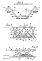
- the illustrated load compensation system includes a first element, as for example a platform 10, to receive applied loading, indicated as downward at L.
- the system also includes a base 11 spaced below the platform.
- the platform may be circular, as in the case of a helicopter landing pad. It itself exerts downward loading L'.
- Means including articulated members supports the first element 10 on the base 11, and acts to resist downward displacement of the element 10 characterized in that the base 11 may move relatively toward and away from the element 10 (or vice versa ) while predetermined loading L is applied to same.
- predetermined loading L is applied to same.
- certain of the articulated members 13 extend longitudinally downwardly and also laterally leftwardly; and others of such members 14 extend longitudinally downwardly and laterally rightwardly; i.e. all members 13 and 14 extend at angles to the platform.
- members 13 are pivotally connected at their upper ends to the platform at 13 a ; and upper ends of members 14 are pivotally connected at 14 a to the platform.
- Pivots 13 a and 14 a for successive links may coincide or closely coincide.
- the links may be generally circularly arranged in a ring, i.e. to have hyperboloid overall configuration, crossing at loci 15.
- the means supporting the platform on the base may for example take the form of motion dampers 16 connected to the members 13 and 14 at their lower ends to resist articulating or pivoting of the link members.
- dampers are offset downwardly from the platform and pivotally connected as at 16 a and 16 b (see Fig. 6) to lower ends of 13 b and 14 b of successive links, so that such lower ends may be displaced generally parallel to the plane of the platform, in response to upward and downward "heaving" movement of the base relative to the platform, whereby the platform tends to remain stabilized in position to compensate for such heaving movement.
- the damper 16 may typically include a piston 17 working lengthwise in the bore 18 a of cylinder 18, and against the pressure of fluid 19 in chamber 20; cylinder rod 18 b connects to pivot 16 b , and piston rod 17 b connects to pivot 16 a .
- the cylinder may be supported as at 21 on the base so that the rods 17 b and 18 b and pivots 16 a and 16 b move horizontally, parallel to the plane of the platform. See Fig. 3.
- Links 13 and 14 extend at equal angles ⁇ to the axes of the rods 17 b and 18 b , and angles ⁇ decrease as the base moves upwardly dynamically relative to the platform; but the supporting force exerted on the platform tends to remain the same so that the platform remains in position. That position is typically the position it assumes under imposed downward static loading, as by helicopter, drill string, or other load source.
- the motion damper may include a liquid containing accumulator 30 connectible as via line 31 a and valve 32 with chamber 20, and if desired, connectible with the chambers 20 of other cylinders associated with pairs of members 13 and 14.
- the accumulator also contains a gas pressure reservoir 31, separated from the liquid 19 a in the accumulator as by a bladder 33.
- Gas (as for example nitrogen) pressure 36 in reservoir 31 is adjustable by gas pump 34 and outlet valve 35; both communicating via line 37 with reservoir 31.
- the initial hydraulic pressure in chamber 20 may be adjusted to balance the imposed static load L on platform 10, associated with an assumed platform initial position.
- Lubricant 34 is applicable to chamber 35, to lubricate the piston and cylinder base.
- a lubricant reservoir appears at 38.
- first connectors pivotally interconnecting certain members 13, and second connectors pivotally interconnecting the other members 14. See for example rod connectors 47 pivotally attached at 47 a and 47 b to mid-portions of links 13; and rod connectors 48 pivotally attached at 48 a and 48 b to mid-portions of links 14.
- rod connectors are to stabilize the mechanism, for example to resist relative rotation of the platform and base, and to resist floating of the platform relative to the base, or floating of the base relative to the platform.
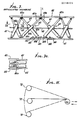
- the modified structure includes a first element such as platform 40, a base 41 below the platform, and means including articulated members 42 and 43 supporting the platform on the base and acting to resist displacement thereof characterized in that the base may move up or down relative to the platform while predetermined loading is applied to the platform which tends to remain in position under applied loading L.
- Members 42 extend downwardly and laterally leftwardly between pivot connections 42 a and 42 b to the platform and base; and members 43 extend downwardly and laterally rightwardly between pivot connections 43 a and 43 b to the platform and base.
- Rods 44 extend horizontally and are pivotally connected at 44 a and 44 b to members 42; and rods 45 extend horizontally and are pivotally connected at 45 a and 45 b to members 43.
- the connections are to cylinders 42 c and 43 c . See Fig. 7 a in this regard.
- the members 42 and 43 include motion dampers, as shown, each damper having a cylinder as at 42 c and 43 c connected to the base, a piston in the cylinder, and piston rods 42 e and 43 e connected to the platform.
- the upward displacement is compensated by displacement of the pistons in the cylinders, as related to pressurized fluid in the cylinders so as to absorb the upward motion without substantially disturbing the level of the static loaded platform.
- the members 42 and 43 may be arranged circularly about an upward central axis, and that they present a hyperboloidal structural arrangement, affording great stability and strength to the equipment. There are at least three pairs (13 and 14) of such members, in a circular arrangement.
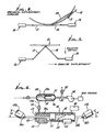
- Fig. 8 shows an application of the compensating equipment 50 (of either Figs. 2 and 3, or Fig. 7 type) to a well derrick 51 on a floating offshore platform 52.
- Underwater floats appear at 53, and structure 54 supports the platform on the floats.
- the platform 40 (assuming device 50 is of Fig. 7 type) centrally suspends a line 55 carrying travelling block 56.
- the latter in turn supports a drill string 57 suspending drilling equipment, as for example a well head stack 58 (blowout preventers, accumulators, and well head connector) adapted to be lowered to the sea bed or floor 59, to attach to a riser pipe 60.
- a well head stack 58 blowout preventers, accumulators, and well head connector
- Fig. 9 shows the derrick 51 construction to comprise a hyperboloidal arrangement of support members.
- the latter include linearly elongated support members (steel, or concrete, or both) certain of which, at 60, extend downwardly and laterally along hyperboloidal directrices in one direction about derrick central vertical axis 61. Ties 63 interconnect the members as shown. A typical joint appears at 64 in Fig. 10.
- Such a hyperboloidal structure saves weight, and optimizes the strength and stability of the derrick, the hyperboloidal compensating unit at the top of the derrick also contributing to reduce weight, and increase strength and stability.
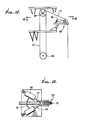
- the means exerting a preload and the platform element 10, in Fig. 12, includes a crown block 70, to which travelling block 56 (that supports the drill string) is connected, as by line 71.
- the line lower end is connected to a draw works, or other control drum or pulley system, indicated at 72.
- the latter is supported on the derrick, which heaves up and down in response to sea wave travel, as described above.
- the blocks 70 and 56 will move up and down relative to the sea floor, even though platform 10 is stabilized. See Fig. 11.
- control means (indicated generally at 73) is provided and engages line 71 to extend or shorten its effective length in response to upward and downward movement, respectively, of the drilling platform, whereby the blocks 70 and 56 maintain their elevations relative to the sea bed.
- the control means 73 includes two piston and cylinder type actuators or dampers 74 as also shown in Fig. 6.
- the cylinders are pivotally connected at 75 to derrick structure 76; and the pistons have rods 77 pivotally connected at 78 to the sheave 78 over which line 71 travels.
- the inward force exerted on the actuators 74 by the sheave is reduced, whereby the pistons and rods 77 extend (to the right, in Figs. 12 and 13) due to the expansion of gas compressed in the cylinders by the pistons, keeping block 56 from moving relative to the sea floor; and as the derrick drops down, the inward force on the actuators 74 is increased, whereby the pistons and rods 77 move inward (to the left in Figs. 12 and 13) keeping block 56 from moving relative to the sea floor.
- the compressed fluid chambers in the cylinders may be connected, as by line 79 whereby pressures in the fluid chambers are equalized. Also, tracks may be provided for sheave inward and outward movement.
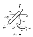
- further vertical dampening may be achieved by the inclusion of an additional dampener 109 pivotally mounted on the base (11) and extending upward to the diagonal members (13 and 14).
- This modification and the resultant effect of vertical loading can be further regulated by control of the pressure of the vertical dampener compression chamber.
- This control can be accomplished by fluid pressure regulation at 110 or the addition of an accumulator 111 to increase chamber volume, or both, as indicated in Fig. 14, with connection to the dampener at 115.
- the vertical mounted dampener 109 reduces both vertical and horizontal loading forces, at a proportional rate.
Landscapes
- Engineering & Computer Science (AREA)
- Mining & Mineral Resources (AREA)
- Life Sciences & Earth Sciences (AREA)
- Geology (AREA)
- Mechanical Engineering (AREA)
- Geochemistry & Mineralogy (AREA)
- Physics & Mathematics (AREA)
- Environmental & Geological Engineering (AREA)
- Fluid Mechanics (AREA)
- Aviation & Aerospace Engineering (AREA)
- General Life Sciences & Earth Sciences (AREA)
- Architecture (AREA)
- Civil Engineering (AREA)
- Structural Engineering (AREA)
- Chemical & Material Sciences (AREA)
- Combustion & Propulsion (AREA)
- Ocean & Marine Engineering (AREA)
- Earth Drilling (AREA)
- Manipulator (AREA)
Applications Claiming Priority (2)
| Application Number | Priority Date | Filing Date | Title |
|---|---|---|---|
| US06/783,679 US4662786A (en) | 1985-10-03 | 1985-10-03 | Dynamic load compensating system |
| US783679 | 1985-10-03 |
Publications (2)
| Publication Number | Publication Date |
|---|---|
| EP0218405A2 true EP0218405A2 (fr) | 1987-04-15 |
| EP0218405A3 EP0218405A3 (fr) | 1988-03-09 |
Family
ID=25130089
Family Applications (1)
| Application Number | Title | Priority Date | Filing Date |
|---|---|---|---|
| EP86307268A Withdrawn EP0218405A3 (fr) | 1985-10-03 | 1986-09-22 | Appareil pour compenser le poids dynamique |
Country Status (5)
| Country | Link |
|---|---|
| US (1) | US4662786A (fr) |
| EP (1) | EP0218405A3 (fr) |
| JP (1) | JPS62125981A (fr) |
| BR (1) | BR8604771A (fr) |
| NO (1) | NO863917L (fr) |
Cited By (1)
| Publication number | Priority date | Publication date | Assignee | Title |
|---|---|---|---|---|
| GB2440520A (en) * | 2006-08-03 | 2008-02-06 | Liam Clear | Motion Compensated Aircraft Platform |
Families Citing this family (22)
| Publication number | Priority date | Publication date | Assignee | Title |
|---|---|---|---|---|
| US4883388A (en) * | 1985-10-03 | 1989-11-28 | Cherbonnier T Dave | Load compensating system |
| US4886397A (en) * | 1987-08-27 | 1989-12-12 | Cherbonnier T Dave | Dynamic load compensating system |
| US4962817A (en) * | 1989-04-03 | 1990-10-16 | A.R.M. Design Development | Active reference system |
| US5154561A (en) * | 1990-04-11 | 1992-10-13 | Lee Donald E | Automated all-weather cargo transfer system |
| US5160219A (en) * | 1991-01-15 | 1992-11-03 | Ltv Energy Products Company | Variable spring rate riser tensioner system |
| US5125769A (en) * | 1991-01-16 | 1992-06-30 | Kyu Lee | Floatable structure |
| US6585455B1 (en) | 1992-08-18 | 2003-07-01 | Shell Oil Company | Rocker arm marine tensioning system |
| US5641248A (en) * | 1993-04-15 | 1997-06-24 | Continental Emsco Company | Variable spring rate compression element and riser tensioner system using the same |
| US5482406A (en) * | 1993-04-15 | 1996-01-09 | Continental Emsco Company | Variable spring rate compression element and riser tensioner system using the same |
| US5628586A (en) * | 1995-06-23 | 1997-05-13 | Continental Emsco Company | Elastomeric riser tensioner system |
| GB9802421D0 (en) * | 1998-02-06 | 1998-04-01 | Head Philip | A riser system for sub sea wells and method of operation |
| US7293939B2 (en) * | 2004-02-10 | 2007-11-13 | Phillip Andrew Abbott | Inclined leg floating production platform with a damper plate |
| US7317260B2 (en) * | 2004-05-11 | 2008-01-08 | Clipper Windpower Technology, Inc. | Wind flow estimation and tracking using tower dynamics |
| US7293670B2 (en) * | 2004-09-08 | 2007-11-13 | Mhe Technologies, Inc. | Upper block |
| ES2351408B1 (es) * | 2005-05-05 | 2011-12-05 | Lockheed Martin Corporation | Plataforma de lanzamiento/captura asistida por robot para un vehículo aéreo no tripulado. |
| FR2890372B1 (fr) * | 2005-09-05 | 2007-11-30 | Total Sa | Procede de montage d'un plateau modulaire support d'equipement sur une structure flexible et mouvante, et plateau modulaire correspondant |
| NL1031263C2 (nl) * | 2006-03-01 | 2007-09-04 | Univ Delft Tech | Vaartuig, bewegingsplatform, werkwijze voor het compenseren voor bewegingen van een vaartuig en gebruik van een Stewart platform. |
| US20080302024A1 (en) * | 2007-06-05 | 2008-12-11 | Gm Global Technology Operations, Inc. | Tunable impedance load-bearing structures |
| NL2005231C2 (en) * | 2010-08-13 | 2012-02-14 | Ampelmann Operations B V | A vessel, a motion platform, a control system, a method for compensating motions of a vessel and a computer program product. |
| EP2953883B1 (fr) * | 2013-02-05 | 2017-04-05 | Barge Master IP B.V. | Dispositif de compensation de mouvement et procédé de transfert de charge |
| CN105129670A (zh) * | 2015-09-09 | 2015-12-09 | 南京晶云船舶配件有限公司 | 一种船舶用可升降操作平台 |
| US20250136253A1 (en) * | 2021-08-27 | 2025-05-01 | Eni S.P.A. | Mooring device and method |
Family Cites Families (20)
| Publication number | Priority date | Publication date | Assignee | Title |
|---|---|---|---|---|
| US27261A (en) * | 1860-02-21 | Molding-machine | ||
| DE709400C (de) * | 1936-12-17 | 1941-08-15 | Roberto Onori | Schwimmende Einrichtung zum Betreuen von auf dem Wasser schwimmenden Fahrzeugen, insbesondere Wasserflugzeugen |
| US2517612A (en) * | 1947-03-29 | 1950-08-08 | Sperry Corp | Stable platform |
| US2842939A (en) * | 1953-10-14 | 1958-07-15 | Neyrpic Ets | Shock absorber for docking of ships |
| US3472032A (en) * | 1967-12-01 | 1969-10-14 | Pan American Petroleum Corp | Production and storage system for offshore oil wells |
| DE1920696C3 (de) * | 1969-04-23 | 1979-02-01 | Fichtel & Sachs Ag, 8720 Schweinfurt | Höhenverstellbares Untergestell für Fernsehgeräte, Schreibmaschinen, Nähmaschinen o.dgl |
| US3743249A (en) * | 1970-04-30 | 1973-07-03 | Shell Oil Co | Heave compensator |
| USRE27261E (en) | 1970-05-11 | 1971-12-28 | Stabilized- offshore drilling apparatus | |
| US3714995A (en) * | 1970-09-04 | 1973-02-06 | Vetco Offshore Ind Inc | Motion compensating apparatus |
| FR2126908B2 (fr) * | 1970-12-16 | 1974-07-05 | Inst Francais Du Petrole | |
| US3752432A (en) * | 1970-12-31 | 1973-08-14 | Universal Oil Prod Co | Vehicle seats |
| US3794125A (en) * | 1971-01-11 | 1974-02-26 | A Nelson | Apparatus and method of maneuver and sustain |
| US3721293A (en) * | 1971-02-16 | 1973-03-20 | Vetco Offshore Ind Inc | Compensating and sensing apparatus for well bore drilling vessels |
| US3791628A (en) * | 1972-07-26 | 1974-02-12 | Ocean Science & Eng | Motion compensated crown block system |
| SU606919A1 (ru) * | 1975-10-20 | 1978-05-15 | Государственный Институт По Проектированию,Исследованию И Испытанию Стальных Конструкций И Мостов "Укрпроектстальконструкция" | Полупогружна бурова платформа |
| GB1511696A (en) * | 1976-09-13 | 1978-05-24 | Gec Mech Handling Ltd | Shipboard desk installations |
| US4379657A (en) * | 1980-06-19 | 1983-04-12 | Conoco Inc. | Riser tensioner |
| US4449854A (en) * | 1981-02-12 | 1984-05-22 | Nl Industries, Inc. | Motion compensator system |
| US4511115A (en) * | 1984-01-27 | 1985-04-16 | Chicago Bridge & Iron Company | Passive structure with energy absorbing capacity |
| FR2575452B1 (fr) * | 1984-12-28 | 1987-11-13 | Inst Francais Du Petrole | Methode et dispositif pour soustraire un element accroche a une installation mobile aux mouvements de cette installation |
-
1985
- 1985-10-03 US US06/783,679 patent/US4662786A/en not_active Expired - Lifetime
-
1986
- 1986-09-22 EP EP86307268A patent/EP0218405A3/fr not_active Withdrawn
- 1986-10-02 JP JP61235452A patent/JPS62125981A/ja active Pending
- 1986-10-02 NO NO863917A patent/NO863917L/no unknown
- 1986-10-02 BR BR8604771A patent/BR8604771A/pt unknown
Cited By (1)
| Publication number | Priority date | Publication date | Assignee | Title |
|---|---|---|---|---|
| GB2440520A (en) * | 2006-08-03 | 2008-02-06 | Liam Clear | Motion Compensated Aircraft Platform |
Also Published As
| Publication number | Publication date |
|---|---|
| JPS62125981A (ja) | 1987-06-08 |
| EP0218405A3 (fr) | 1988-03-09 |
| BR8604771A (pt) | 1987-06-30 |
| NO863917D0 (no) | 1986-10-02 |
| US4662786A (en) | 1987-05-05 |
| NO863917L (no) | 1987-04-06 |
Similar Documents
| Publication | Publication Date | Title |
|---|---|---|
| US4662786A (en) | Dynamic load compensating system | |
| US4886397A (en) | Dynamic load compensating system | |
| US4883388A (en) | Load compensating system | |
| US6691784B1 (en) | Riser tensioning system | |
| US3791628A (en) | Motion compensated crown block system | |
| US4272059A (en) | Riser tensioner system | |
| US11142287B2 (en) | System and method for compensation of motions of a floating vessel | |
| US4616707A (en) | Riser braking clamp apparatus | |
| RU2463435C2 (ru) | Система натяжения для водоотделяющей колонки с верхним натяжением | |
| US4962817A (en) | Active reference system | |
| US4617998A (en) | Drilling riser braking apparatus and method | |
| US4487150A (en) | Riser recoil preventer system | |
| US7063159B2 (en) | Multi-purpose coiled tubing handling system | |
| US6648074B2 (en) | Gimbaled table riser support system | |
| US4688764A (en) | Crown block compensator | |
| US4620692A (en) | Crown block compensator | |
| US3897045A (en) | Riser pipe and guide line tensioning apparatus | |
| WO2002029206A1 (fr) | Systeme support a tubes prolongateurs pour tablier a cardans | |
| WO2004013452A1 (fr) | Dispositif tensionneur de tube prolongateur | |
| US20050103500A1 (en) | Motion compensation system for watercraft connected to subsea conduit | |
| US10253579B2 (en) | Motion compensation system for a load hanging from a mobile unit with a main cylinder and a secondary cylinder | |
| US20070003375A1 (en) | Heave compensation system | |
| USRE28322E (en) | Floating rig-motion compensator | |
| Hatleskog | Drill string compensators and riser tensioning systems for offshore drilling | |
| ZA200201398B (en) | Riser tensioning system. |
Legal Events
| Date | Code | Title | Description |
|---|---|---|---|
| PUAI | Public reference made under article 153(3) epc to a published international application that has entered the european phase |
Free format text: ORIGINAL CODE: 0009012 |
|
| AK | Designated contracting states |
Kind code of ref document: A2 Designated state(s): DE FR GB IT NL |
|
| PUAL | Search report despatched |
Free format text: ORIGINAL CODE: 0009013 |
|
| AK | Designated contracting states |
Kind code of ref document: A3 Designated state(s): DE FR GB IT NL |
|
| 17P | Request for examination filed |
Effective date: 19880826 |
|
| 17Q | First examination report despatched |
Effective date: 19881028 |
|
| STAA | Information on the status of an ep patent application or granted ep patent |
Free format text: STATUS: THE APPLICATION IS DEEMED TO BE WITHDRAWN |
|
| 18D | Application deemed to be withdrawn |
Effective date: 19900707 |