EP0218420A2 - Système de positionnement de composants à optimalisation de contrainte - Google Patents
Système de positionnement de composants à optimalisation de contrainte Download PDFInfo
- Publication number
- EP0218420A2 EP0218420A2 EP86307380A EP86307380A EP0218420A2 EP 0218420 A2 EP0218420 A2 EP 0218420A2 EP 86307380 A EP86307380 A EP 86307380A EP 86307380 A EP86307380 A EP 86307380A EP 0218420 A2 EP0218420 A2 EP 0218420A2
- Authority
- EP
- European Patent Office
- Prior art keywords
- components
- placement
- function
- routing
- rectangles
- Prior art date
- Legal status (The legal status is an assumption and is not a legal conclusion. Google has not performed a legal analysis and makes no representation as to the accuracy of the status listed.)
- Withdrawn
Links
Images

Classifications
-
- G—PHYSICS
- G06—COMPUTING OR CALCULATING; COUNTING
- G06F—ELECTRIC DIGITAL DATA PROCESSING
- G06F30/00—Computer-aided design [CAD]
- G06F30/30—Circuit design
- G06F30/39—Circuit design at the physical level
- G06F30/392—Floor-planning or layout, e.g. partitioning or placement
Definitions
- the present invention relates to the placement of components on a carrier, and more particularly to a constrained optimization component placement system in which wire length is the objective function being minimized and routing resource congestion is used to define a constraint function that must be satisfied.
- the component placement problem when applied to digital circuits consists of finding the optimal arrangement of components on a carrier with respect to some predefined criteria, such as total wire length.
- the carrier is the medium on which the circuit is laid out, such as a semiconductor chip or printed circuit board, and component refers to a physical entity containing one or more circuit elements, such as gates or macro cells on a chip or chips on a printed circuit board.
- Finding the optimal arrangement of components potentially involves evaluating nl possible configurations where n is the number of components. Since modern placement problems involve thousands of components, such a combinatorial approach is impractical. Therefore, many heuristics have been developed in an attempt to approach the optimum solution.
- the actual component placement task typically is performed in two phases: 1) constructive initial placement and 2) iterative improvement placement.
- Constructive initial placement begins with all or part of the components unplaced and determines an initial location for each component on the carrier surface. Once a component is positioned, it generally is not moved.
- Some current initial placement algorithms include cluster development which forms the initial placement by selecting components one at a time to connect to previously placed components; min-cut techniques which attempt to place devices such that crossings of cut lines are minimized; and least squares method which forms the initial placement by forming a system of equations using eigenvector techniques, solving for the optimum solution and then mapping onto the carrier. In all of these techniques, there is room for substantial error.
- the goal of iterative improvement placement is to take a set of initially placed components and attempt to improve that placement.
- Normally iterative improvement placers are limited to interchanging components between "slots" on the carrier which indicate legal locations for certain types and sizes of components. These slots are defined based on the initial positons and attributes of the components being considered. This restriction eliminates the need to dynamically check for component overlap and thus results in much faster placement techniques.
- Most of the techniques involve choosing a primary component and then searching for a secondary component location to which the primary component can be moved to improve the placement.
- Such algorithms include. force directed pairwise interchange and unconnected set interchange.
- the wire length metric can be computed in many different ways as shown in Fig. 1.
- the idea behind this metric is that, as the wire length decreases, the routing resources required to complete the interconnections decrease and the routing completion rate should increase.
- Fig. la for the nodes 10 in a net 12 to be interconnected, one way is to form the complete graph, as shown in Fig. lb, for each net and sum either the rectilinear or Euclidean length of each of the edges 14. This is clearly pessimistic in terms of actual wire length required to form the interconnections since only one path is required from one node to any other node. Another method shown in Fig.
- lc is to sum up over all nets half of the perimeter distance of the minimum bounding box 16 enclosing the net 12.
- the wire length estimated by this method represents the absolute minimum wire length required to complete the interconnections using rectilinear paths.
- a third technique shown in Fig. 1d is to generate a minimum spanning tree (MST) for the net based upon the imposed wiring rules and summing up either the rectilinear or Euclidean length of each edge 14 in the graph. This last is the most accurate of these methods since it most closely models the way in which a router tries to optimally route the interconnections.
- MST minimum spanning tree
- a network requiring five interconnections 20 has a total rectilinear connection length of 46 units.
- the available routing resource consists of one channel 22 with two tracks 24.
- An area of high congestion exists on the right side of the channel 22 due to connections C-H, B-H and D-G competing for the same routing tracks. In this case the congestion has forced connection D-G to fail.
- the interchanging of components A and D as shown in Fig. 2b increases the rectilinear connection length to 55 units, but the congestion is diminished and all connections are successfully completed.
- Fig. 2 illustrates how simply minimizing wire length can cause routing failures to occur by creating regions of local congestion.
- the present invention provides a constrained optimization component placement system in which wire length is the objective function being minimized and routing resource congestion is used to define a constraint function that must be satisfied.
- a carrier is partitioned into rectangles and iterative exchange placement is carried out for all components within each rectangle simultaneously with pin assignment. If the new score using the constrained optimization function is less than the old score, the exchange is accepted, otherwise the exchange is rejected.
- Each rectangle is subsequently partitioned and the process repeated until a terminal condition, such as minimum number of components within a rectangle, is achieved.
- constrained optimization problems there exists a function called the objective function whose value is to be minimized (or maximized) subject to some constraints on the values which the function or its parameters can assume.
- An example is to minimize F(x) m x 2 +2x+3 subject tox k 1.
- F(x) is the objective function
- x ⁇ 1 is the constraint function.
- the solution for this problem is F(x) - 6 which occurs at x - 1.
- a technique for solving the constrained optimization problem is a penalty function method.
- a modified objective function is formed by adding a penalty term P(x) to the original objective function to account for the constraints, i.e., J - F(x)+P(x).
- P(x) a penalty term
- J - F(x)+P(x) a penalty term that is not necessary to drive the constraint to zero, but only to reach some acceptable balance between the objective function (wire length) and the constraint function (congestion).
- Two possible constraint conditions are "homogeneity" of the routing resource use over the carrier and "capacity violation" of specific routing resources.
- Homogeneity of routing resource use means that routing resources needed by net interconnections, pins and routing barriers are roughly equal over the entire carrier surface. The deviation one is willing to accept to reduce the wire length is controlled by the weight W given to the penalty term. Smoothing out the routing resource use has two primary advantages: 1) congestion build up is constrained so that fewer connections fail due to lack of sufficient local routing resources and 2) potential thermal effect problems are lessened since energy and heat dissipation tends to be evened out along with routing resource use.
- a homogeneity constraint function is as follows: where n - number of cells ei - expected use of cell i
- the homogeneity constraint may unnecessarily increase the wire length, especially if the total amount of routing resources available substantially exceeds the amount needed to complete the specified interconnections.
- the capacity violation constraint is concerned with whether any of the routing resources are over used, i.e., whether any routing resources are used beyond some given (or calculated) capacity limits such that routing failures are likely to result. Capacity is used as a measure of the amount of available routing resource per unit area. This constraint is less constricting since it only prevents wire length reduction in cases where the routing resource capacity would be exceeded.
- the capacity violation constraint function may be written as: where g(x) - 0 (x ⁇ 0) ; 1 (x > 0) ci - capacity of cell i
- the position and amount of routing resources consumed by pins and routing barriers is known, but not those for the interconnections.
- the amount of routing resources needed is approximately equal to the Euclidean or rectilinear length of the specific connection being considered. The exact path that the route takes is not known.
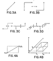
- FIG. 3 A sample interconnection is shown in Fig. 3 for some of the possible routing paths. This assumes that only rectilinear, non-meandering paths are allowed. Since normally making a bend in a routing path is expensive because of the need for via insertion or non-preferred wiring, the more bends in a path the less likely the path is generated. However, exactly where bends occur is so dependent on the order in which the connections are routed and the nature of the router that it is not possible to predict with any accuracy. Thus, a uniform distribution of required routing resources over the area of a rectangle which bounds the connection is assumed, as shown in Fig. 4.
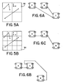
- pins and routing barriers To keep track of this use where the interaction of all of the connections, pins and routing barriers is considered requires storing the routing resource use over some unit area of the carrier. This is done by subdividing the carrier into a two dimensional array of cells 30 as shown in Fig. 5. Each cell represents a certain area of the carrier and, therefore, a certain capacity of routing resources.
- the routing resource use is tracked by calculating the expected cell use for each connection, with the exact cell use for pins and routing barriers being known.
- the expected cell use for the connections and the exact cell use for the pins and routing barriers is added together for each cell.
- the size of the cell used determines the level of resolution with which the congestion is viewed. If the cells are too large, then the differences between various configurations cannot be seen. Ideally, the cell size should equal the track width so that any variation in congestion between various component configurations can be identified. But the decrease in cell size increases the number of cells and computation time required to calculate expected use of the cells.
- a final consideration is concurrent component placement and pin assignment.
- Current placers when searching for good placements, do so by representing the interconnections as being to some predefined point(s) on the components. As shown in Fig. 6 this results in suboptimal modeling of the interconnections when judging the quality of the placement.
- the best pin to connect to on the component may change based on the relative position of the components.
- new placements are generated based on component connection points which may be potentially far from optimal. Therefore, after each trial placement, or only after successful trial placements, pin assignment is performed. The pin assignment is scored using the same function as for component placement.
- the placement algorithm may be described as follows:
- the scoring function based on the modified objective function, is u + Wp where W is a weighting factor, u is the mean cell utilization which has a direct relationship to wire length, and p is the penalty term using homogeneity or capacity violation criteria.
- W is a weighting factor
- u is the mean cell utilization which has a direct relationship to wire length
- p is the penalty term using homogeneity or capacity violation criteria.
- the scoring function is used to achieve an optimum balance between wire length and congestion.
- the present invention provides an iterative improvement placement system which supplies a congestion constraint to an objective wire length function, concurrently places components and makes pin assignments, and uses a hierarchical approach to increase resolution resulting in a near optimum component placement system which reduces interconnect failures.
Landscapes
- Engineering & Computer Science (AREA)
- Computer Hardware Design (AREA)
- Physics & Mathematics (AREA)
- Theoretical Computer Science (AREA)
- Architecture (AREA)
- Evolutionary Computation (AREA)
- Geometry (AREA)
- General Engineering & Computer Science (AREA)
- General Physics & Mathematics (AREA)
- Design And Manufacture Of Integrated Circuits (AREA)
- Data Exchanges In Wide-Area Networks (AREA)
Applications Claiming Priority (2)
| Application Number | Priority Date | Filing Date | Title |
|---|---|---|---|
| US78183785A | 1985-09-30 | 1985-09-30 | |
| US781837 | 1985-09-30 |
Publications (2)
| Publication Number | Publication Date |
|---|---|
| EP0218420A2 true EP0218420A2 (fr) | 1987-04-15 |
| EP0218420A3 EP0218420A3 (fr) | 1988-09-07 |
Family
ID=25124106
Family Applications (1)
| Application Number | Title | Priority Date | Filing Date |
|---|---|---|---|
| EP86307380A Withdrawn EP0218420A3 (fr) | 1985-09-30 | 1986-09-25 | Système de positionnement de composants à optimalisation de contrainte |
Country Status (3)
| Country | Link |
|---|---|
| EP (1) | EP0218420A3 (fr) |
| JP (1) | JPS6275872A (fr) |
| IL (1) | IL80122A0 (fr) |
Cited By (3)
| Publication number | Priority date | Publication date | Assignee | Title |
|---|---|---|---|---|
| DE4003535A1 (de) * | 1989-02-06 | 1990-08-16 | Hitachi Ltd | Einrichtung zum zuordnen von anschlussklemmen unter beruecksichtigung elektrischer beschraenkungen |
| EP0403826A3 (fr) * | 1989-06-20 | 1991-10-23 | Digital Equipment Corporation | Minimisation du coût de l'interconnexion d'objets liés électroniquement |
| EP0431532A3 (en) * | 1989-12-04 | 1993-07-28 | Matsushita Electric Industrial Co., Ltd. | Placement optimization system aided by cad |
Families Citing this family (1)
| Publication number | Priority date | Publication date | Assignee | Title |
|---|---|---|---|---|
| JP4723740B2 (ja) * | 2001-03-14 | 2011-07-13 | 富士通株式会社 | 密度一様化配置問題の最適解探索方法および密度一様化配置問題の最適解探索プログラム |
Family Cites Families (1)
| Publication number | Priority date | Publication date | Assignee | Title |
|---|---|---|---|---|
| US4495559A (en) * | 1981-11-02 | 1985-01-22 | International Business Machines Corporation | Optimization of an organization of many discrete elements |
-
1986
- 1986-09-23 IL IL80122A patent/IL80122A0/xx unknown
- 1986-09-25 EP EP86307380A patent/EP0218420A3/fr not_active Withdrawn
- 1986-09-26 JP JP61227928A patent/JPS6275872A/ja active Pending
Cited By (3)
| Publication number | Priority date | Publication date | Assignee | Title |
|---|---|---|---|---|
| DE4003535A1 (de) * | 1989-02-06 | 1990-08-16 | Hitachi Ltd | Einrichtung zum zuordnen von anschlussklemmen unter beruecksichtigung elektrischer beschraenkungen |
| EP0403826A3 (fr) * | 1989-06-20 | 1991-10-23 | Digital Equipment Corporation | Minimisation du coût de l'interconnexion d'objets liés électroniquement |
| EP0431532A3 (en) * | 1989-12-04 | 1993-07-28 | Matsushita Electric Industrial Co., Ltd. | Placement optimization system aided by cad |
Also Published As
| Publication number | Publication date |
|---|---|
| JPS6275872A (ja) | 1987-04-07 |
| IL80122A0 (en) | 1986-12-31 |
| EP0218420A3 (fr) | 1988-09-07 |
Similar Documents
| Publication | Publication Date | Title |
|---|---|---|
| US5790841A (en) | Method for placement of clock buffers in a clock distribution system | |
| US7225116B2 (en) | Method for eliminating routing congestion in an IC layout | |
| US6557145B2 (en) | Method for design optimization using logical and physical information | |
| Donath et al. | Timing driven placement using complete path delays | |
| US5798936A (en) | Congestion-driven placement method and computer-implemented integrated-circuit design tool | |
| US6185722B1 (en) | Three dimensional track-based parasitic extraction | |
| US6668365B2 (en) | Quadratic programming method for eliminating cell overlap and routing congestion in an IC layout | |
| US8037441B2 (en) | Gridded-router based wiring on a non-gridded library | |
| US6480991B1 (en) | Timing-driven global placement based on geometry-aware timing budgets | |
| US6415422B1 (en) | Method and system for performing capacitance estimations on an integrated circuit design routed by a global routing tool | |
| US5974245A (en) | Method and apparatus for making integrated circuits by inserting buffers into a netlist | |
| US20040107408A1 (en) | Method of optimizing signal lines within circuit, optimizing apparatus, recording medium having stored therein optimizing program, and method of designing circuit and recording medium having stored therein program for designing circuit | |
| US20030126578A1 (en) | Topological global routing for automated IC package interconnect | |
| US20070245280A1 (en) | System and method for placement of soft macros | |
| PEDRAM | Hierarchical placement and floorplanning in BEAR | |
| US6397375B1 (en) | Method for managing metal resources for over-the-block routing in integrated circuits | |
| EP0218420A2 (fr) | Système de positionnement de composants à optimalisation de contrainte | |
| Zhong et al. | Algorithms for simultaneous satisfaction of multiple constraints and objective optimization in a placement flow with application to congestion control | |
| US6186676B1 (en) | Method and apparatus for determining wire routing | |
| US6408426B1 (en) | Method for determining locations of interconnect repeater farms during physical design of integrated circuits | |
| Ravichandran et al. | Physical layout automation for system-on-packages | |
| JP3548398B2 (ja) | 概略経路決定方法および概略経路決定方式 | |
| Khokhani et al. | Placement of variable size Circuits on LSI Masterslices | |
| JP3422839B2 (ja) | 半導体集積回路の論理セル分割処理方法 | |
| Kudva et al. | Performance Driven Optimization of Network Length in Physical Placement |
Legal Events
| Date | Code | Title | Description |
|---|---|---|---|
| PUAI | Public reference made under article 153(3) epc to a published international application that has entered the european phase |
Free format text: ORIGINAL CODE: 0009012 |
|
| AK | Designated contracting states |
Kind code of ref document: A2 Designated state(s): DE GB NL |
|
| PUAL | Search report despatched |
Free format text: ORIGINAL CODE: 0009013 |
|
| AK | Designated contracting states |
Kind code of ref document: A3 Designated state(s): DE GB NL |
|
| STAA | Information on the status of an ep patent application or granted ep patent |
Free format text: STATUS: THE APPLICATION IS DEEMED TO BE WITHDRAWN |
|
| 18D | Application deemed to be withdrawn |
Effective date: 19890331 |
|
| RIN1 | Information on inventor provided before grant (corrected) |
Inventor name: KARGER, PATRICK G. |