EP0218429A1 - Kupplung von Rohren - Google Patents
Kupplung von Rohren Download PDFInfo
- Publication number
- EP0218429A1 EP0218429A1 EP86307430A EP86307430A EP0218429A1 EP 0218429 A1 EP0218429 A1 EP 0218429A1 EP 86307430 A EP86307430 A EP 86307430A EP 86307430 A EP86307430 A EP 86307430A EP 0218429 A1 EP0218429 A1 EP 0218429A1
- Authority
- EP
- European Patent Office
- Prior art keywords
- sleeve
- pipe
- pipe length
- socket
- region
- Prior art date
- Legal status (The legal status is an assumption and is not a legal conclusion. Google has not performed a legal analysis and makes no representation as to the accuracy of the status listed.)
- Granted
Links
- 230000008878 coupling Effects 0.000 title claims abstract description 7
- 238000010168 coupling process Methods 0.000 title claims abstract description 7
- 238000005859 coupling reaction Methods 0.000 title claims abstract description 7
- 238000007789 sealing Methods 0.000 claims abstract description 68
- 239000004033 plastic Substances 0.000 claims abstract description 64
- 229920003023 plastic Polymers 0.000 claims abstract description 64
- 230000006835 compression Effects 0.000 claims abstract description 16
- 238000007906 compression Methods 0.000 claims abstract description 16
- 239000000463 material Substances 0.000 claims description 17
- 238000000034 method Methods 0.000 claims description 9
- 229920001169 thermoplastic Polymers 0.000 claims description 9
- 239000004416 thermosoftening plastic Substances 0.000 claims description 9
- 238000010438 heat treatment Methods 0.000 claims description 7
- 239000000565 sealant Substances 0.000 claims description 6
- 239000003795 chemical substances by application Substances 0.000 claims description 5
- 239000007767 bonding agent Substances 0.000 claims description 4
- 229920000642 polymer Polymers 0.000 claims description 4
- 238000004519 manufacturing process Methods 0.000 claims description 3
- 239000012815 thermoplastic material Substances 0.000 claims description 3
- 238000001816 cooling Methods 0.000 claims description 2
- 239000002861 polymer material Substances 0.000 claims 1
- 239000004927 clay Substances 0.000 abstract description 3
- 239000000203 mixture Substances 0.000 abstract description 3
- 229920001971 elastomer Polymers 0.000 description 3
- 239000000853 adhesive Substances 0.000 description 2
- 230000001070 adhesive effect Effects 0.000 description 2
- 239000000806 elastomer Substances 0.000 description 2
- -1 polyethylene Polymers 0.000 description 2
- 239000000126 substance Substances 0.000 description 2
- 239000004698 Polyethylene Substances 0.000 description 1
- 239000004743 Polypropylene Substances 0.000 description 1
- 239000010425 asbestos Substances 0.000 description 1
- 230000015556 catabolic process Effects 0.000 description 1
- 238000010276 construction Methods 0.000 description 1
- 238000006731 degradation reaction Methods 0.000 description 1
- 239000003000 extruded plastic Substances 0.000 description 1
- 238000002347 injection Methods 0.000 description 1
- 239000007924 injection Substances 0.000 description 1
- 229910052500 inorganic mineral Inorganic materials 0.000 description 1
- 238000003780 insertion Methods 0.000 description 1
- 230000037431 insertion Effects 0.000 description 1
- 239000011707 mineral Substances 0.000 description 1
- 230000002093 peripheral effect Effects 0.000 description 1
- 229920000573 polyethylene Polymers 0.000 description 1
- 229920000098 polyolefin Polymers 0.000 description 1
- 229920001155 polypropylene Polymers 0.000 description 1
- 229920000915 polyvinyl chloride Polymers 0.000 description 1
- 239000004800 polyvinyl chloride Substances 0.000 description 1
- 238000003825 pressing Methods 0.000 description 1
- 239000012858 resilient material Substances 0.000 description 1
- 229910052895 riebeckite Inorganic materials 0.000 description 1
- 239000005060 rubber Substances 0.000 description 1
- 239000004576 sand Substances 0.000 description 1
- 239000002904 solvent Substances 0.000 description 1
- 229920001187 thermosetting polymer Polymers 0.000 description 1
- XLYOFNOQVPJJNP-UHFFFAOYSA-N water Substances O XLYOFNOQVPJJNP-UHFFFAOYSA-N 0.000 description 1
- 238000003466 welding Methods 0.000 description 1
Images
Classifications
-
- F—MECHANICAL ENGINEERING; LIGHTING; HEATING; WEAPONS; BLASTING
- F16—ENGINEERING ELEMENTS AND UNITS; GENERAL MEASURES FOR PRODUCING AND MAINTAINING EFFECTIVE FUNCTIONING OF MACHINES OR INSTALLATIONS; THERMAL INSULATION IN GENERAL
- F16L—PIPES; JOINTS OR FITTINGS FOR PIPES; SUPPORTS FOR PIPES, CABLES OR PROTECTIVE TUBING; MEANS FOR THERMAL INSULATION IN GENERAL
- F16L49/00—Connecting arrangements, e.g. joints, specially adapted for pipes of brittle material, e.g. glass, earthenware
- F16L49/02—Joints with a sleeve or socket
Definitions
- This invention relates to the coupling together of pipes such as are used for sewers, drains, or conduits, of the kind in which a spigot end of one pipe length is inserted into a socket at the end of another pipe length.
- the invention is particularly applicable to pipes of glazed or unglazed vitrified clayware. asbestos compositions, and other mineral materials.
- Plastics jointing means may for example comprise pipe coupling sleeves of plastics material provided with rubber or similar sealing rings at both ends, for receiving the ends of respective plane pipe lengths.
- pipe lengths may be fitted with plastics sleeves which project to form sockets for receiving spigot pipe ends.
- Pipe joints of the latter kind are disclosed for example in our British patent specifications 971,124 and 1,152.740, and in specification 1,417,371.
- a pipe length has a spigoted end, and a socketed end, and the socketed end comprises a sleeve of flexible resilient thermoplastics material protruding beyond the pipe end for receiving a spigoted end of a similar pipe length, a resilient sealing ring or band is provided on the external circumference of the end of the pipe length between the pipe length and the plastics sleeve, the plastics sleeve having been shrink-fitted over the pipe end and the said ring or band under radial or hoop stress whereby the said ring or band is maintained under compression.
- the regions of the plastics sleeve which are not in-contact with the ring or band are shrink-fitted into intimate contact with the surface of the pipe length.
- the plastics sleeve is fitted for example by heating an injection-moulded or extruded sleeve of thermoplastics material, forcibly expanding the heated sleeve before or during mounting of the sleeve on the pipe end, fitting the expanded sleeve over the pipe end and the said ring or band, and subjecting the hot sleeve to radial or hoop compression at least in the region of the said ring or band as the hot sleeve cools and shrinks.
- UK patent specification 1,417,371 discloses a pipe jointing system, in which one end of a pipe length is provided with an external sealing band which may be a sealing ring, or a moulded-on collar of plastics material.
- the other pipe end has a plastics socket fitted on by being forcibly expanded and then allowed to shrink onto the outside circumferential surface of the pipe, with a polymeric adhesive or sealant between the pipe surface and the plastics sleeve.
- UK patent specification 971,124 discloses a pipe jointing system, in which a pipe length has an external rib or sealing ring at one end, and a plastics socket at the other end, attached in a similar manner, however a polymer bonding agent or sealant is not used, but a resilient sealing ring may be fitted on the pipe end to be trapped by the shrunk-on plastics sleeve.
- This is not a practical arrangement, because in practice, the shrinking plastics sleeve does not exert significant pressure on the sealing ring and therefore does not compress it, so that the sealing ring does not significantly enhance sealing between the plastics sleeve and the pipe surface, on the contrary by holding the plastics sleeve away from the pipe surface it may impair sealing.
- the present invention overcomes the disadvantages of previously proposed processes and provides a simple method of securing a plastics sleeve on a pipe end with an excellent seal, by shrinkage fitting.
- the sealing ring or band is pre-compressed to a substantial extent while the plastics sleeve is enabled to shrink into intimate contact with the pipe surface and with the sealing ring or band while the latter is compressed.
- the plastics sleeve has cooled and set, the externally applied compression is removed, and the stress in the sealing ring or band provides excellent sealing between the plastics socket and the pipe surface. The need for a polymer bonding agent or sealant is eliminated.
- the sealing ring or band Before assembly, the sealing ring or band is fitted either to the circumference of the pipe, or to the plastics sleeve. In the latter case, the sleeve and sealing ring must be initially slightly under-sized relative to the external circumference of the pipe. In the former case, the sealing ring or band can be fitted on the plain external surface of the pipe end, or can be located in a circumferential groove in the pipe surface. A locating groove will usually be desirable, when an 0-ring is used.
- a pipe length is fitted with a plastics socket at an end of the pipe length, by heating, expanding and shrink-fitting a thermoplastic sleeve onto the end of the pipe length, and the plastics sleeve is provided with a resilient annular sealing element for engaging the external circumferential surface of the pipe length, in a region of the plastics sleeve that is not heated, expanded and shrunk onto the pipe length but instead is dimensional to fit on the pipe length.
- a polymer bonding agent or sealant may additionally be provided between the shrink-fitted region of the plastics sleeve, and the external surface of the pipe length, or a resilient sealing ring or band may be provided between the external surface of the pipe length and the internal surface of the plastics sleeve where the latter is shrink-fitted, being subject to externally applied compression as described above.
- the resilient sealing element provided in a region of the sleeve that is not shrink-fitted, provides a back up seal relative to the region that is shrink-fitted.
- the portion of the sleeve that projects from the end of the pipe length to form a socket may be provided with a resilient annular sealing element to seal on the spigot end of an inserted pipe length.
- the other end of each pipe length may have an external peripheral rib, sealing ring or band (resilient or stiff) to make sealing engagement with the internal surface of the plastics socket of an adjacent pipe length.
- the plastics socket elements may for example be made of moulded or extruded polyolefine, including reinforced grades e.g. polyethylene, polypropylene, or polyvinyl chloride of suitable grade, or other thermoplastic material which has a "themal memory” so as to shrink on cooling, and which has suitable mechanical properties and chemical inertness, for use in the required environment, for example as underground drains.
- reinforced grades e.g. polyethylene, polypropylene, or polyvinyl chloride of suitable grade, or other thermoplastic material which has a "themal memory” so as to shrink on cooling, and which has suitable mechanical properties and chemical inertness, for use in the required environment, for example as underground drains.
- a prefabricated plastics sleeve to form a socket, is fitted to a pipe end by heating and expanding the sleeve and fitting it on the pipe end, then allowing it to cool and contract onto the pipe end, a bonding and/or sealing agent being provided between the external surface of the pipe and the internal surface of the sleeve, and the hot sleeve being subjected to radial or hoop compression at least in the region of the said agent, as the hot sleeve cools and shrinks.
- the compressible sealing band or ring can be of any suitable elastomer (thermoplastic or thermosetting). with adequate mechanical properties, resistance to compression set, and chemical inertness.
- the sealine ring or band, to be compressed between the shrink-fitted plastics socket and the pipe surface should be relatively soft, for example 35-60 Shore. It may for example comprise a relatively soft 0-ring seated in a groove in the circumferential surface of the pipe length, or a band of material such as that used for tyre inner tubes.
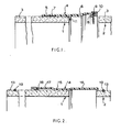
- FIG. 1 shows first and second pipe ends of fired clay pipes 1, 2.
- Each pipe has a plain spigoted end 3.
- each pipe has a sleeve 4 of thermoplastics material of which one portion 5 is fastened on the external surface of the pipe, and the other portion 6 projects from the end of the pipe to form a socket which in use receives the spigot end 3 of the adjacent pipe.
- the plastics sleeve is injection-moulded, with dimensions such that its internal diameter is somewhat less than the external diameter of the pipe, so that in its as-moulded state it could not be pushed onto the pipe end. It is made of a thermoplastic material which exhibits "shape memory” or “thermal memory”, that is to say. when heated until it is soft it can be deformed, in particular by being expanded, and when it subsequently cools it shrinks back to its initial dimensions.
- the region 5 of the sleeve that is to fit over the pipe end is heated to a temperature below that at which its plastic material is degraded, causing the sleeve to expand to an internal diameter greater than the external diameter of the pipe end.
- the heated and softened plastics sleeve may be forcibly expanded while it is hot and soft, by the act of pushing it over the pipe end, or by means of an expansion mandrel.
- the sleeve preferably has a register rib or register lugs 11 to locate it relative to the end of the pipe 1.
- the presence of the register rib or lugs is believed to contribute to maintaining the shape and dimensions of the socket region 6 while the opposite region 5 of the sleeve expands and shrinks.
- the region 5 can be heated in any convenient way for example by hot water, steam, hot air, radiant heat, but is preferably heated by being dipped in a fluidised bed of hot sand as this has been found to provide very uniform and controllable heating. After the region 5 of the plastics sleeve has been fitted over the pipe end in this way, it is allowed to cool, whereupon it shrinks onto the external surface of the pipe, and conforms to any irregularities in the surface of the pipe end by localised deformation of the inner surface of the sleeve.
- Sealing between the inner surface of the socket and the outer surface of the pipe depends on the accuracy with which the plastics material can conform to the pipe surface, and in practice, simple shrink-fitting does not provide a reliable seal.
- the pipe has an annular band 7 of relatively soft elastomer fitted onto its external surface, at a position spaced from the pipe end and fairly close to the end of the region 5 of the plastics sleeve.
- compression dies which may be rigid, flexible, or inflatable by internal pressure
- pressure is thereby applied to the plastics sleeve.
- the material of the plastics sleeve remains capable of transmitting compression from the dies to the sealing band 7, so that the latter is compressed with a force substantially greater than that which can be exerted by simple thermal shrinkage of the plastics material of the sleeve.
- the material of the sealing ring is thereby pre-stressed so that, after the plastics sleeve has cooled and set in position, and the pressure dies have been removed, a very substantial radial pressure exists between the sealing ring. the pipe, and the internal surface of the plastics sleeve, providing a reliable seal.
- the spigot end may have an external sealing ring or band to engage the internal surface of the plastics socket, for example as described in 1.417.371 or 971.124.
- the socket may be fitted with a sealing ring of resilient material, in any convenient way.
- the sealing ring may be secured in the end of the socket by adhesive, by solvent welding, by direct bonding, or mechanically.
- the socket has a sealing ring 8 with a flange 9 held in position by a locking ring 10 snap-fitted on the end of the socket, in a manner analogous to the well known Hepsleve pipe coupling.
- FIG. 2 illustrates another embodiment of the invention.
- a plastics sleeve 14 is shrink-fitted on one end of a clay pipe 1 to form a projecting socket 16.
- the region 15 of the plastics sleeve that is shrink-fitted on the pipe 1 is an intermediate region.
- the sleeve end region 17 opposite the socket region 16 has a greater internal diameter than the external diameter of the pipe, and is provided with a sealing ring 18 at its end.
- the sealing ring 18 is attached to the sleeve region 17 in any convenient way, for example in any of the ways mentioned with reference to the sealing ring of the socket described with reference to Figure 1.
- the sleeve region 17 is initially moulded over-sized relative to the external surface of the pipe length whereas the intermediate region 15 is initially under-sized relative to the external surface of the pipe length.
- the sealing ring 18 is designed to form a compression seal between the internal surface of the sleeve region 17, and the external surface of the pipe, when the plastics sleeve 14 is fitted over the pipe end.
- the intermediate region 15 and optionally the socket region 16 are heated to a temperature below the degradation temperature of the plastics material of the sleeve, at least the region 15 is expanded and fitted over the pipe end, and the sleeve is allowed to cool so that the region 15 shrinks into intimate contact with the external surface of the pipe end.
- a bonding or sealing agent may be provided between the region 15 of the sleeve, and the external surface of the pipe.
- the shrink-fitted region 15 provides a primary seal between the socket and the pipe.
- the sealing ring 18 provides a secondary or back up seal.
- the socket region 16 can seal against the inserted spigot pipe end 13 in any convenient way for example any of the ways mentioned above with reference to Figure 1.
- an elastomeric O-ring 19 is seated in a circumferential groove in the external surface of the spigot end 13, to seal against the internal surface of the socket 16.
- the illustrated pipe joints have plastics coupling sleeves onto the external surfaces of pipe lengths of uniform external diameter.
- This construction is suitable for conventional pipe laying in trenches.
- Pipes are however also laid by direct insertion in the ground, the pipe lengths being pulled or pushed into the ground (for example by a mole plough or a pipe jacking technique).
- the pipe joints should have external diameters not greater than the external diameter of the pipes themselves.
- the pipes may be provided with rebates at their ends to receive the plastics sleeves so that these are flush with, or inset relative to, the external surfaces of the pipes.
- the plastics sleeve will usually be a simple tube of constant internal and external diameter, for example a length cut from an extruded plastics pipe.
Landscapes
- Engineering & Computer Science (AREA)
- General Engineering & Computer Science (AREA)
- Mechanical Engineering (AREA)
- Lining Or Joining Of Plastics Or The Like (AREA)
- Joints With Sleeves (AREA)
- Mutual Connection Of Rods And Tubes (AREA)
- Rigid Pipes And Flexible Pipes (AREA)
- Branch Pipes, Bends, And The Like (AREA)
- Joints Allowing Movement (AREA)
- Non-Disconnectible Joints And Screw-Threaded Joints (AREA)
Priority Applications (1)
| Application Number | Priority Date | Filing Date | Title |
|---|---|---|---|
| AT86307430T ATE61095T1 (de) | 1985-09-30 | 1986-09-26 | Kupplung von rohren. |
Applications Claiming Priority (2)
| Application Number | Priority Date | Filing Date | Title |
|---|---|---|---|
| GB8524006A GB2181201B (en) | 1985-09-30 | 1985-09-30 | Coupling pipes |
| GB8524006 | 1985-09-30 |
Publications (2)
| Publication Number | Publication Date |
|---|---|
| EP0218429A1 true EP0218429A1 (de) | 1987-04-15 |
| EP0218429B1 EP0218429B1 (de) | 1991-02-27 |
Family
ID=10585922
Family Applications (1)
| Application Number | Title | Priority Date | Filing Date |
|---|---|---|---|
| EP86307430A Expired - Lifetime EP0218429B1 (de) | 1985-09-30 | 1986-09-26 | Kupplung von Rohren |
Country Status (6)
| Country | Link |
|---|---|
| US (1) | US4711473A (de) |
| EP (1) | EP0218429B1 (de) |
| AT (1) | ATE61095T1 (de) |
| DE (1) | DE3677690D1 (de) |
| EG (1) | EG18671A (de) |
| GB (1) | GB2181201B (de) |
Cited By (2)
| Publication number | Priority date | Publication date | Assignee | Title |
|---|---|---|---|---|
| EP0814203A3 (de) * | 1993-11-11 | 1998-02-11 | Hepworth Building Products Limited | Drainagesystem |
| EP2388502A2 (de) * | 2010-05-21 | 2011-11-23 | Martin Niederthanner | Fluidschlauchunterstützungselement |
Families Citing this family (10)
| Publication number | Priority date | Publication date | Assignee | Title |
|---|---|---|---|---|
| US5120153A (en) * | 1988-11-07 | 1992-06-09 | Vassallo Research And Development Corp. | Fitting socket with integral reinforcing ring |
| GB2269643A (en) * | 1992-08-15 | 1994-02-16 | Edward Whitehead | Heat shrink plastic/pipe/duct/conduit jointing couplers |
| CA2098938C (fr) * | 1993-06-22 | 1997-12-02 | Pierre Longpre | Joint d'etancheite pour tuyaux de regards et puisards |
| US5876039A (en) * | 1994-02-18 | 1999-03-02 | Press-Seal Gasket Corporation | Folded gasket and method of casting same in a wall |
| GB2295212A (en) * | 1994-11-17 | 1996-05-22 | Hepworth Building Prod | Pipe coupling |
| WO1996033362A1 (en) * | 1995-04-17 | 1996-10-24 | Advanced Metal Components Inc. | Forming a connection to an object |
| US6206430B1 (en) | 1999-07-07 | 2001-03-27 | Inter-Med, Llc. | Connector and attachment mechanism for a lumen |
| FR2818729B1 (fr) * | 2000-12-22 | 2004-11-05 | Bonna Sabla | Tuyau ou analogue ; bague d'about femelle et procede de fabrication d'un tel tuyau ou analogue |
| USD917027S1 (en) | 2019-12-18 | 2021-04-20 | Lasalle Bristol Corporation | Non-return device valve support member |
| USD924378S1 (en) | 2019-12-18 | 2021-07-06 | Lasalle Bristol Corporation | Non-return device valve member |
Citations (6)
| Publication number | Priority date | Publication date | Assignee | Title |
|---|---|---|---|---|
| AU428807B2 (en) * | 1968-04-09 | 1969-10-16 | The Hepworth Iron Company Limited | Improvements in or relating to pipe couplings |
| GB1417371A (en) * | 1973-01-22 | 1975-12-10 | Clow Corp | Pipe length having coupling means |
| FR2292918A1 (fr) * | 1974-11-27 | 1976-06-25 | Bresso Claude | Ouvrage forme de caissons en beton juxtaposes |
| FR2339121A1 (fr) * | 1976-01-22 | 1977-08-19 | Raychem Corp | Manchon d'accouplement a reprise thermique |
| AT365759B (de) * | 1980-03-31 | 1982-02-10 | Eternit Werke Hatschek L | Rohrkupplung und verfahren zu deren herstellung |
| DD230056A1 (de) * | 1984-10-19 | 1985-11-20 | Energieversorgung Ingbetrieb | Nichtloesliche elastische rohrverbindung fuer zylinderfoermige rohre, insbesondere aus einem spannungsempfindlichen werkstoff mittels schrumpfmuffe |
Family Cites Families (9)
| Publication number | Priority date | Publication date | Assignee | Title |
|---|---|---|---|---|
| GB971124A (en) * | 1962-03-22 | 1964-09-30 | Hepworth Iron Co Ltd | Improvements in or relating to joints for pipes as used for sewers, drains or conduits |
| US3415287A (en) * | 1964-08-21 | 1968-12-10 | Raychem Corp | Protective covering and article |
| GB1116877A (en) * | 1965-07-30 | 1968-06-12 | Graviner Colnbrook Ltd | Improvements relating to radiation detectors |
| GB1152740A (en) * | 1966-12-22 | 1969-05-21 | Hepworth Iron Co Ltd | Improvements in or relating to Pipe Couplings. |
| NL6903512A (de) * | 1969-03-07 | 1970-09-09 | ||
| GB1394219A (en) * | 1971-07-20 | 1975-05-14 | Tac Construction Materials Ltd | Pipe joints |
| CH596457A5 (de) * | 1973-10-09 | 1978-03-15 | Raychem Corp | |
| BE880992A (fr) * | 1979-01-05 | 1980-05-02 | Raychem Corp | Perfectionnements aux dispositifs a reprise thermique |
| GB2076489B (en) * | 1980-05-22 | 1984-05-16 | Secr Defence | Pipe repair joint |
-
1985
- 1985-09-30 GB GB8524006A patent/GB2181201B/en not_active Expired
-
1986
- 1986-09-26 DE DE8686307430T patent/DE3677690D1/de not_active Expired - Lifetime
- 1986-09-26 EP EP86307430A patent/EP0218429B1/de not_active Expired - Lifetime
- 1986-09-26 AT AT86307430T patent/ATE61095T1/de active
- 1986-09-29 US US06/912,822 patent/US4711473A/en not_active Expired - Fee Related
- 1986-09-30 EG EG615/86A patent/EG18671A/xx active
Patent Citations (6)
| Publication number | Priority date | Publication date | Assignee | Title |
|---|---|---|---|---|
| AU428807B2 (en) * | 1968-04-09 | 1969-10-16 | The Hepworth Iron Company Limited | Improvements in or relating to pipe couplings |
| GB1417371A (en) * | 1973-01-22 | 1975-12-10 | Clow Corp | Pipe length having coupling means |
| FR2292918A1 (fr) * | 1974-11-27 | 1976-06-25 | Bresso Claude | Ouvrage forme de caissons en beton juxtaposes |
| FR2339121A1 (fr) * | 1976-01-22 | 1977-08-19 | Raychem Corp | Manchon d'accouplement a reprise thermique |
| AT365759B (de) * | 1980-03-31 | 1982-02-10 | Eternit Werke Hatschek L | Rohrkupplung und verfahren zu deren herstellung |
| DD230056A1 (de) * | 1984-10-19 | 1985-11-20 | Energieversorgung Ingbetrieb | Nichtloesliche elastische rohrverbindung fuer zylinderfoermige rohre, insbesondere aus einem spannungsempfindlichen werkstoff mittels schrumpfmuffe |
Cited By (2)
| Publication number | Priority date | Publication date | Assignee | Title |
|---|---|---|---|---|
| EP0814203A3 (de) * | 1993-11-11 | 1998-02-11 | Hepworth Building Products Limited | Drainagesystem |
| EP2388502A2 (de) * | 2010-05-21 | 2011-11-23 | Martin Niederthanner | Fluidschlauchunterstützungselement |
Also Published As
| Publication number | Publication date |
|---|---|
| ATE61095T1 (de) | 1991-03-15 |
| DE3677690D1 (de) | 1991-04-04 |
| EG18671A (en) | 1993-10-30 |
| US4711473A (en) | 1987-12-08 |
| GB8524006D0 (en) | 1985-11-06 |
| GB2181201A (en) | 1987-04-15 |
| EP0218429B1 (de) | 1991-02-27 |
| GB2181201B (en) | 1989-12-20 |
Similar Documents
| Publication | Publication Date | Title |
|---|---|---|
| US4752511A (en) | Method and apparatus for sealing the space between pipes and linings therefor | |
| US5340160A (en) | Thermoplastic saddle in two parts for repairing or renovating a pipe line with branch pipe and repaired or renovated pipe with a saddle | |
| US7134204B2 (en) | Integral restraint system and method of manufacture for plastic pipe | |
| US4711473A (en) | Coupling pipes | |
| US5494106A (en) | Method for sealing between a lining and borehole, casing or pipeline | |
| AU2005314238B2 (en) | Combination seal and restraing system for plastic pipe | |
| US9267632B1 (en) | Coupling for pipe, and related methods | |
| US6079095A (en) | Forming a flange on a tubular member lined with a thermoplastic liner | |
| KR930009045B1 (ko) | 라이닝된 흄관 제조방법 | |
| US3848904A (en) | Pipe having coupling means | |
| US5223189A (en) | Method of sealing lateral connections for pipe liners | |
| CA3079217A1 (en) | Method and apparatus for repairing a length of pipe or a main/lateral pipe junction | |
| US4124422A (en) | Method of producing flexible pipe with socket section | |
| EP0217189B1 (de) | Auskleidung und Verfahren zum Auskleiden eines Rohres | |
| US4097070A (en) | High-strength pipe coupling | |
| EP0459542B1 (de) | Vorrichtung zum Verbinden eines dünnwandigen Schlauches mit einem rohrförmigen Element | |
| US6554325B1 (en) | Pipe fitting and method for the production thereof | |
| US8709318B2 (en) | Method and apparatus for belling plastic pipe | |
| US3459445A (en) | Pipe fitting and method of manufacture | |
| RU2129685C1 (ru) | Способ герметичного соединения по меньшей мере двух пластмассовых элементов и устройство для его осуществления | |
| GB1590782A (en) | Insulated pipelines | |
| JP5089730B2 (ja) | マンホール用耐震性継手及びその製造方法並びに取付け方法 | |
| GB2075086A (en) | Duct linings | |
| US4245858A (en) | Conduit structure | |
| GB2184804A (en) | A plastic shrink socket for joining two tube ends |
Legal Events
| Date | Code | Title | Description |
|---|---|---|---|
| PUAI | Public reference made under article 153(3) epc to a published international application that has entered the european phase |
Free format text: ORIGINAL CODE: 0009012 |
|
| AK | Designated contracting states |
Kind code of ref document: A1 Designated state(s): AT BE CH DE FR GB IT LI LU NL SE |
|
| 17P | Request for examination filed |
Effective date: 19870601 |
|
| 17Q | First examination report despatched |
Effective date: 19880831 |
|
| RAP1 | Party data changed (applicant data changed or rights of an application transferred) |
Owner name: HEPWORTH BUILDING PRODUCTS LIMITED |
|
| GRAA | (expected) grant |
Free format text: ORIGINAL CODE: 0009210 |
|
| AK | Designated contracting states |
Kind code of ref document: B1 Designated state(s): AT BE CH DE FR GB IT LI LU NL SE |
|
| PG25 | Lapsed in a contracting state [announced via postgrant information from national office to epo] |
Ref country code: LI Effective date: 19910227 Ref country code: SE Effective date: 19910227 Ref country code: CH Effective date: 19910227 Ref country code: NL Effective date: 19910227 Ref country code: FR Effective date: 19910227 Ref country code: AT Effective date: 19910227 |
|
| REF | Corresponds to: |
Ref document number: 61095 Country of ref document: AT Date of ref document: 19910315 Kind code of ref document: T |
|
| ITF | It: translation for a ep patent filed | ||
| REF | Corresponds to: |
Ref document number: 3677690 Country of ref document: DE Date of ref document: 19910404 |
|
| REG | Reference to a national code |
Ref country code: CH Ref legal event code: PL |
|
| NLV1 | Nl: lapsed or annulled due to failure to fulfill the requirements of art. 29p and 29m of the patents act | ||
| EN | Fr: translation not filed | ||
| PG25 | Lapsed in a contracting state [announced via postgrant information from national office to epo] |
Ref country code: LU Free format text: LAPSE BECAUSE OF NON-PAYMENT OF DUE FEES Effective date: 19910930 |
|
| PLBE | No opposition filed within time limit |
Free format text: ORIGINAL CODE: 0009261 |
|
| STAA | Information on the status of an ep patent application or granted ep patent |
Free format text: STATUS: NO OPPOSITION FILED WITHIN TIME LIMIT |
|
| 26N | No opposition filed | ||
| REG | Reference to a national code |
Ref country code: GB Ref legal event code: IF02 |
|
| PGFP | Annual fee paid to national office [announced via postgrant information from national office to epo] |
Ref country code: GB Payment date: 20050921 Year of fee payment: 20 |
|
| PGFP | Annual fee paid to national office [announced via postgrant information from national office to epo] |
Ref country code: DE Payment date: 20050922 Year of fee payment: 20 |
|
| PGFP | Annual fee paid to national office [announced via postgrant information from national office to epo] |
Ref country code: IT Payment date: 20050927 Year of fee payment: 20 |
|
| REG | Reference to a national code |
Ref country code: GB Ref legal event code: PE20 |
|
| PGFP | Annual fee paid to national office [announced via postgrant information from national office to epo] |
Ref country code: BE Payment date: 20051121 Year of fee payment: 20 |
|
| PG25 | Lapsed in a contracting state [announced via postgrant information from national office to epo] |
Ref country code: GB Free format text: LAPSE BECAUSE OF EXPIRATION OF PROTECTION Effective date: 20060925 |
|
| BE20 | Be: patent expired |
Owner name: *HEPWORTH BUILDING PRODUCTS LTD Effective date: 20060926 |