EP0218475A2 - Siebeinrichtung mit Stäben - Google Patents
Siebeinrichtung mit Stäben Download PDFInfo
- Publication number
- EP0218475A2 EP0218475A2 EP86307601A EP86307601A EP0218475A2 EP 0218475 A2 EP0218475 A2 EP 0218475A2 EP 86307601 A EP86307601 A EP 86307601A EP 86307601 A EP86307601 A EP 86307601A EP 0218475 A2 EP0218475 A2 EP 0218475A2
- Authority
- EP
- European Patent Office
- Prior art keywords
- rake
- bars
- guide rail
- movement
- rollers
- Prior art date
- Legal status (The legal status is an assumption and is not a legal conclusion. Google has not performed a legal analysis and makes no representation as to the accuracy of the status listed.)
- Granted
Links
- 238000012216 screening Methods 0.000 title claims abstract description 40
- 239000007788 liquid Substances 0.000 claims abstract description 28
- 239000011343 solid material Substances 0.000 claims abstract description 15
- 238000011144 upstream manufacturing Methods 0.000 claims abstract description 13
- 230000001154 acute effect Effects 0.000 claims abstract description 6
- 239000007787 solid Substances 0.000 claims description 23
- 230000008878 coupling Effects 0.000 claims 3
- 238000010168 coupling process Methods 0.000 claims 3
- 238000005859 coupling reaction Methods 0.000 claims 3
- 239000000463 material Substances 0.000 abstract description 3
- 239000002910 solid waste Substances 0.000 abstract description 3
- 230000002708 enhancing effect Effects 0.000 abstract 1
- 238000006073 displacement reaction Methods 0.000 description 10
- 238000000034 method Methods 0.000 description 9
- 239000002245 particle Substances 0.000 description 9
- 230000008569 process Effects 0.000 description 8
- 230000009977 dual effect Effects 0.000 description 6
- 230000007246 mechanism Effects 0.000 description 6
- 230000000694 effects Effects 0.000 description 4
- 238000012545 processing Methods 0.000 description 4
- 239000002699 waste material Substances 0.000 description 4
- 230000009471 action Effects 0.000 description 3
- 230000008901 benefit Effects 0.000 description 3
- 238000010276 construction Methods 0.000 description 3
- 235000013399 edible fruits Nutrition 0.000 description 3
- 230000001681 protective effect Effects 0.000 description 3
- 230000002441 reversible effect Effects 0.000 description 3
- 238000000926 separation method Methods 0.000 description 3
- 206010040844 Skin exfoliation Diseases 0.000 description 2
- 235000012055 fruits and vegetables Nutrition 0.000 description 2
- 238000012986 modification Methods 0.000 description 2
- 230000004048 modification Effects 0.000 description 2
- 238000005406 washing Methods 0.000 description 2
- 235000002595 Solanum tuberosum Nutrition 0.000 description 1
- 244000061456 Solanum tuberosum Species 0.000 description 1
- 238000009825 accumulation Methods 0.000 description 1
- 230000003247 decreasing effect Effects 0.000 description 1
- 238000013461 design Methods 0.000 description 1
- 238000011143 downstream manufacturing Methods 0.000 description 1
- 238000001914 filtration Methods 0.000 description 1
- 239000010419 fine particle Substances 0.000 description 1
- 235000013305 food Nutrition 0.000 description 1
- 230000005484 gravity Effects 0.000 description 1
- 238000004519 manufacturing process Methods 0.000 description 1
- 235000021328 potato skins Nutrition 0.000 description 1
- 238000005096 rolling process Methods 0.000 description 1
- 238000007790 scraping Methods 0.000 description 1
- 230000001360 synchronised effect Effects 0.000 description 1
- 235000013311 vegetables Nutrition 0.000 description 1
Images


Classifications
-
- B—PERFORMING OPERATIONS; TRANSPORTING
- B01—PHYSICAL OR CHEMICAL PROCESSES OR APPARATUS IN GENERAL
- B01D—SEPARATION
- B01D29/00—Filters with filtering elements stationary during filtration, e.g. pressure or suction filters, not covered by groups B01D24/00 - B01D27/00; Filtering elements therefor
- B01D29/01—Filters with filtering elements stationary during filtration, e.g. pressure or suction filters, not covered by groups B01D24/00 - B01D27/00; Filtering elements therefor with flat filtering elements
-
- B—PERFORMING OPERATIONS; TRANSPORTING
- B01—PHYSICAL OR CHEMICAL PROCESSES OR APPARATUS IN GENERAL
- B01D—SEPARATION
- B01D29/00—Filters with filtering elements stationary during filtration, e.g. pressure or suction filters, not covered by groups B01D24/00 - B01D27/00; Filtering elements therefor
- B01D29/44—Edge filtering elements, i.e. using contiguous impervious surfaces
- B01D29/445—Bar screens
-
- B—PERFORMING OPERATIONS; TRANSPORTING
- B01—PHYSICAL OR CHEMICAL PROCESSES OR APPARATUS IN GENERAL
- B01D—SEPARATION
- B01D29/00—Filters with filtering elements stationary during filtration, e.g. pressure or suction filters, not covered by groups B01D24/00 - B01D27/00; Filtering elements therefor
- B01D29/62—Regenerating the filter material in the filter
- B01D29/64—Regenerating the filter material in the filter by scrapers, brushes, nozzles, or the like, acting on the cake side of the filtering element
- B01D29/6469—Regenerating the filter material in the filter by scrapers, brushes, nozzles, or the like, acting on the cake side of the filtering element scrapers
- B01D29/6484—Regenerating the filter material in the filter by scrapers, brushes, nozzles, or the like, acting on the cake side of the filtering element scrapers with a translatory movement with respect to the filtering element
Definitions
- the present invention generally relates to an apparatus for removing solids from liquid flow streams, and more particularly, to an improved bar screen apparatus for such purpose.
- Screens comprising a plurality of bars in closely spaced side-by side relation so as to define a plurality of narrow elongated flow openings having a width narrower than the width of solid materials to be screened are commonly utilized in a variety of processing systems for separating solid materials from a liquid flow stream.
- processing systems for separating solid materials from a liquid flow stream.
- Typical applications include waste treatment systems for removing solid waste materials from a liquid stream, fruit and vegetable washing systems for removing the cleaned fruit and vegetables from the liquid stream in which they are washed, and food processing operations for removing potato peelings, fruit skins and the like from the liquid processing stram.
- Such conventional bar screens have the disadvantage that solids of any length, having a width narrower than the width of the spacing between the bars, can pass through the screen, and thus, either contaminate the downstream processing line or require further screening or filtering of the flow stream.
- a screen is designed with more closely spaced bars in an effort to minimize such undesirable passage of solids through the screen, such screens have been found to unduly restrict the liquid flow, resulting in increased head losses in the system.
- Conventional screens have experienced further problems in connection with the efficient removal of solids that adhere and accumulate around the screen bars during the screening process.
- Another object of the present invention is to provide a bar screen apparatus as characterized above that is adapted to screen and obstruct the flow of most solids that are even narrower than the spacing between the bars of the screen.
- a further object is to provide a screen apparatus of the foregoing type with an improved raking device for the efficient removal of solids that accumulate on the screen.
- Still another object is to provide an improved bar screen apparatus of the above kind that is of relatively simple construction, and thus, lends itself to economical manufacture and reliable use.
- Yet another object is to provide a screen apparatus with an improved raking device which is conveniently adapted to being automatically driven by a variety of driving means.
- the screening apparatus of the present invention incorporates a new and improved design for the arrangement of the bars which constitute the screen. More specifically, the screen bars are designed to be in a substantially parallel relation to each other while at the same time being disposed at an acute angle to the overall direction of flow. According to a preferred embodiment of this invention, the screen bars are disposed in such a manner that the trailing end of any bar is substantially in longitudinal alignment with the leading end of the adjacent bar. Such an arrangement allows more efficient screening of finer particles without the corresponding increase in head losses due to decreased flow rates that would occur when conventional systems are adapted for the screening of fine particles.
- the screen bars are designed to include a plurality of apertures along their active region, which further minimizes head losses while facilitating the screening process.
- Increased efficiency in the removal of accumulated screened solid material is achieved, according to this invention, by the provision of an improved raking device that fits into the spaces between the screen bars and can be conveniently displaced laterally, by manual or automatic means, in order to remove accumulated solid material from the screening area. Means are further provided for maintaining the raking device in inoperative engagement with the screen during the raking operation
- the disclosed bar screening apparatus provides simple, convenient, efficient and easily automated screening as described below in detail.
- FIGS. l and 2 of the drawings there is shown a bar screening apparatus l0 embodying the present invention disposed within an illustrative flow channel ll through which a liquid flow stream is passing in the direction of the arrow.
- the flow channel ll may be part of a waste treatment system, a fruit or vegetable washing or processing operation, or any other like process system in which the flow stream carries solids that must be separated and removed from the liquid stream.
- the illustrated screening apparatus l0 includes a screen l2 consisting of a support bar l4 (FIGS.
- the bar screen l2 is mounted on a pair of support rails l3, l3′ in the flow stream in order to perform the screening function.
- the bar screen l2 in this case lies in a plane with the upper end thereof slanted in a downstream direction.
- the bars of the bar screen each have an upstream relative flat face disposed at an acute angle to the direction of the flow stream so as to effect screening of even relatively thin solid waste materials without significantly restricting liquid flow through.
- the leading edge of one bar is in substantially longtitudinal alignment with the trailing end of the adjacent bar.
- the illustrated bars l5, as best shown in FIG. 3, are positioned at a perpendicular distance ⁇ d ⁇ from each other with the upstream face of each bar being disposed at an angle ⁇ with respect to the direction of flow stream travel.
- the choice of the separation ⁇ d ⁇ between the bars and the angle ⁇ preferably is made in such a way that the leading end l5a of one bar is in substantial longitudinal alignment with the trailing end l5b of the adjacent bar.
- Such angular displacement of the bars l5 prevents a direct flow path for solid materials in the flow direction and causes the solids to come into contact with and begin adhering to the surfaces of the bars.
- the bars of the screen are formed with a plurality of aperatures l5c which function to further reduce the head losses by allowing an increased volume of liquid to flow through at a given time, and which also facilitate the screening process by acting as collection points where the adherence of solid particles is initiated and gradually builds up.
- the provision of such apertures particularly increases the screening efficiency when the flow stream contains long and thin solid material, such as strips of paper or like objects, potato skins, fruit peelings or other such leaf-like matter, the screening of which often is difficult and inefficient when using conventional bar screening techniques.
- the increased exposed surface area of the bars by virtue of the apertures therein provide improved screening of such fine solid particles, and the effectiveness of the apertures is enhanced because of the angular orientation of the bars.
- the diameter of the apertures is designed such that the apertures do not detract from the mechanical strength of the screen bars.
- the screening apparatus is provided with a raking device that includes a rake l6 which has a series of projections l7 designed to fit between the bars l5 of the bar screen l2.
- the projections l7 on the rake l6 are formed with a slanted edge or side l7A which has a slope corresponding to the positional angle ⁇ of the screen bars l5 so that the edge or side l7A can ride in close adjacent relation to the upstream face of the bar.
- each projection l7 is vertically oriented and is connected to the slanted side l7A by a rounded end l7C.
- Such an arrangement permits the placement of the rake projections l7 between the slanted bars l5 of the screen l2 so that when the rake is moved laterally along the bars of the screen, it effectively removes the solid material that has accumulated or is adhering to the surfaces of the screen bars.
- the apertures l5c are formed in the bars in that portion of the bar which are contacted by the projection l7 during the raking stroke.
- the rake l6 For supporting the rake for lateral movement along the rails l3, l3′, the rake l6 is supported at its opposed end by rollers l8, l8′.
- the rake l6 also is connected through a pair of linking arms l9, l9′ to a cross brace 20, which in turn is supported for movement on the rails l3, l3′ by a pair of rollers 2l, 2l′.
- the linking arms l9, l9′ are fixedly secured to the rake l6, but are pivotably connected to the shaft for the rollers 2l, 2l′ so that the rake and linking arms can be pivoted relative to the cross brace 20.
- the rake l6 is coupled to a suitable drive means.
- a suitable drive means For this purpose an L-shaped plate 22 is mounted on the cross brace 20, from which a ball-bearing screw 23 is fixedly coupled in upwardly extending relation.
- the ball-bearing screw 23 operatively engages a ball-bearing nut 25A fixedly mounted within a tubular drive shaft 25 of a suitable drive motor 24.
- Rotational driving movement of the tubular drive shaft 25 will rotate the ball-bearing nut 25A contained therein, causing the ball-bearing screw 23 and the rake l6 coupled thereto to be advanced or retracted relative to the ball-bearing nut 25A and the screen l2.
- the end of the ball-bearing screw 23 is moved upwardly into the tubular shaft 25 upon raising movement of the rake.
- the ball-bearing screw 23, as is known, requires extremely reduced energizing torque and contributes towards minimal power requirements for operating the rake.
- the screw 23 in this case is covered on its end proximate to the cross brace 20 by a protective tube 26 which extends over the lowermost active area of the screw 23 and a protective seal 26A is provided on the end of the tube to prevent exposure to the surroundings.
- the tubular drive shaft 25 for the ball-bearing screw 23 in this instance is supported by a ball-bearing housing 27, which in turn is carried by a main support plate 27A fixed between the support rails l3 and l3′.
- the support rails l3 and l3′ have an upper guide rail 28 and a lower guide rail 29, with a ramp plate 30 connecting the upper and lower guide rails at a point at or beyond the upper end of the bar screen l2.
- a section of the upper guide rail 28, specifically the portion facing the ramp plate 30, is formed with an opening within which a flap plate 3l is pivotably attached by means of a hinge 3lA (FIG.
- the supports l3, l3′ in this case have inwardly directed flanges or rails 28A and l0 for protecting the guide rails from exposure to waste materials.
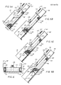
- FIGS. 4A-C The operation of the raking device is illustrated in FIGS. 4A-C.
- the raking device is located on the upper rail 28 before a raking cycle begins.
- the motor 24 can then be actuated to rotate the shaft 25 and nut 25A in a direction which lowers the ball-bearing screw 23 and moves the rake cross brace 20, and hence the rake l6, in a generally downward direction along the length of the upper rail 28, by the rolling motion of rollers 2l, 2l′ and l8, l8′, respectively. Since the length of the upper rail 28 is less than that of the lower rail 29 the rollers l8, l8′ of rake body l6 eventually drop from the end of the top rail 28 onto the lower guide rail 29 at a location adjacent the bottom of the screen.
- the upper portion of the raking device as defined by the cross brace 20 and the rollers 2l, 2l′, is still positioned on the upper rail 28.
- the motor is operated to drive the the ball-bearing screw 23 in a reverse direction.
- the ball-bearing screw 23 then starts retracting and pulls the raking device up with the rollers l8, l8′ riding on the lower guide roll 29 and the cross brace rollers 2l, 2l′ riding on the upper rail 28.
- the rollers l8, l8′ start moving upwardly along the incline offered by the ramp plate 30 (FIG. 4C) as the screw 23 continues to pull the rake l6 in an upward direction.
- the rollers l8, l8′ make contact with the flap plate 3l and continue moving up and onto the upper rail without obstruction because the flap plate 'opens' upwardly by the freedom of the pivotal motion provided by the hinge 30A.
- the flap plate 3l falls back under its own weight to form a continuous path along the upper rail for the return motion of the rake rollers l8, l8′.
- a torsion spring may also be used with the hinge 3lA to ensure proper closing of the ramp plate 3l.
- the linking arms l9,l9′ provide the pivotal motion of the rake with respect to the cross brace 20 because of the rotatable connection of the arms to the cross brace.
- the effect of the foregoing cycle of operation is that the projections on the rake body contact the bar screen only when it is raking away the solid particles accumulated on it and no such contact occurs during its return to the lower end of the bar screen, thereby preventing any obstruction to the flow stream and dislodging of adhering particles back into the flow stream.
- An added advantage of such drive arrangement is that the drive operating mechanism is maintained above the liquid level throughout the screening process.
- the screen apparatus is generally mounted at an angle of 45-60° with respect to the flow stream, certain applications require mounting angles of up to 90°. In such cases there is some chance of the rake body rollers slipping off the upper guide rail during the return movement of the rake along the rails 28. The presence of the upper rail 28A constrains any such displacement of the rake body rollers.
- FIG. 5a there is shown an alternative embodiment of a bar screening apparatus according to the present invention.
- This embodiment provides an improved mechanism for supporting the rake device for lateral displacement across the length of the bar screen and for maintaining the raking device in engagement with the bar screen for effecting relatively thorough removal of accumulated solids therein.
- the raking device is provided with a dual roller arrangement which, in addition to providing smooth lateral displacement of the rake device, serves as a means for maintaining the projections of the rake device in between the bars of the bar screen as the raking action progresses.
- the bar screening apparatus includes a screen 40, similar to that previously described, mounted at the lower end of a pair of support rails 4l disposed at an angle to the vertical.
- the support rails 4l in this case include a lower guide rail 42 and an upper guide rail 44.
- a rake 45 shown in FIG. 5A in a ready position at the lower end of the screen 40, is affixed to the lower end of linking arms 46, which are pivotably coupled to a cross brace member 48, in a manner similar to that previously described.
- a pair of forward rollers 49 are disposed at opposite ends of the cross brace 48 and a dual roller arrangement 50 is provided at opposed ends of the rake 45.
- the dual roller arrangements 50 each comprise a lower roller 5l mounted in the plane of the linking arms 46 and the forward rollers 49, and a roller 52 mounted in raised offset relation to the lower roller 5l on a support plate 54 which is secured to the ends of the rake 45 by bolts 55.
- Each support plate 54 preferably is adjustably mountable on the rake so that the upper rollers 52 may be disposed at a selected elevated distance ⁇ l ⁇ above the plane of the linking arms 46 and the lower roller 5l.
- the rake again is coupled to a suitable drive means capable of displacing the rake through the bar screen according to a predefined sequence of motion.
- a suitable drive means capable of displacing the rake through the bar screen according to a predefined sequence of motion.
- an L-shaped plate 60 is attached to the the cross brace 48 and carries a ball-bearing nut 62, which operatively engages a ball screw 6l.
- the ball screw 6l is coupled at one end to a bearing 64 for relative rotational movement, the bearing 64 being mounted on a plate 65 running across the support rails 4l.
- the other end of the screw 6l may be driven by a suitable drive motor for moving the nut 62 and the rake 45 connected thereto relative to the screw 6l and the screw 40.
- each upper guide rail 44 is formed with a cut out 66 and a flap plate 68 is pivotably secured to the upper guide rail 44 in the cut out 66 by means of a hinge 69.
- Each flap plate 68 is moveable from a normal downardly pivoted position, as shown in FIG. 5, with a lower end thereof engaging the lower guide rail 42 and a raised position that permits movement of the rake past the flap plate 68 upon completing a raking stroke.
- the drive motor may be operated in the opposite direction so that the rake is moved in a reverse direction.
- the lower rake rollers 5l will encounter the flap plates 68, which now functions as ramps connecting the upper and lower guide rails 42, 44, and the rollers will be directed back onto the upper guide rail 44, moving the projections of the rake 45 away from their operative positions between the bars of the screen 4l.
- the rake 45 and rollers 5l on the upper guide rail will bring the rollers 5l to cut out sections 75 adjacent the bottom of the upper guide rails 44, at which point the rollers will drop back onto the lower rails 42 positioning the rake 45 in its ready position for the next cycle of operation.
- the supports 4l in this case each are provided with a further flange or rail 76 which extends over the lower portion of the upper guide rail 44 for preventing contaminates from entering the cut out 75 in the upper guide rail.
- the dual roller arrangements 50 cooperate with both the upper and lower guide rails 42, 44 of the supports 4l for maintaining the rake projections in reliable engaging relationship between the bars of the screen 40 during the raking operation.
- the support plates 54 for the rollers 5l, 52 are adjusted such that during the raking operation the lower rollers 5l ride on the upper surface of the lower guide rails 42 and the upper rollers 52 engage the underside surfaces of the upper guide rails 44.
- rollers 5l, 52 will pass through and under the flap plates 68, enabling the flat plates to be used as a ramp for guiding return movement of the rake onto the upper guide rail.
- the rollers 5l, 52 are angularly disposed with respect to each other in a plane substantially parallel to that of the ramp plates 68 when in lowered position, the result of which is that both the upper and lower rollers 5l, 52 tend to engage and force the plate in its upward pivotal movement.
- the raking process may be made completely automatic by linking the drive mechanism to some form of sensing means which tracks the position of the raking device in order to control the alternating directions required of the drive mechanism.
- sensing means which tracks the position of the raking device in order to control the alternating directions required of the drive mechanism.
- magnetic rings can be mounted over either end of the protective tube FIGS. l-4 and magnetic sensors which are suitably mounted on the guide rails can be used to determine the start and end of the required downward and upward motion of the ball-bearing screw and hence the rake.
- the bar screening apparatus of the present invention provides increased efficiency in the screening of fine solid particles within a flow stream, by using an improved bar screen which results in increased flow rates and minimal head losses and by using an improved raking device which may be automatically driven to efficiently and positively remove solid particles accumulated on and/or adhering to the bar screen as a result of the screening process.
Landscapes
- Chemical & Material Sciences (AREA)
- Chemical Kinetics & Catalysis (AREA)
- Filtration Of Liquid (AREA)
- Combined Means For Separation Of Solids (AREA)
Applications Claiming Priority (4)
| Application Number | Priority Date | Filing Date | Title |
|---|---|---|---|
| US78422685A | 1985-10-04 | 1985-10-04 | |
| US908828 | 1986-09-18 | ||
| US06/908,828 US4792394A (en) | 1985-10-04 | 1986-09-18 | Bar screening apparatus |
| US784226 | 2001-02-16 |
Publications (3)
| Publication Number | Publication Date |
|---|---|
| EP0218475A2 true EP0218475A2 (de) | 1987-04-15 |
| EP0218475A3 EP0218475A3 (en) | 1988-08-10 |
| EP0218475B1 EP0218475B1 (de) | 1991-01-02 |
Family
ID=27120252
Family Applications (1)
| Application Number | Title | Priority Date | Filing Date |
|---|---|---|---|
| EP86307601A Expired - Lifetime EP0218475B1 (de) | 1985-10-04 | 1986-10-02 | Siebeinrichtung mit Stäben |
Country Status (5)
| Country | Link |
|---|---|
| US (1) | US4792394A (de) |
| EP (1) | EP0218475B1 (de) |
| CA (1) | CA1295555C (de) |
| DE (1) | DE3676414D1 (de) |
| ES (1) | ES2020939B3 (de) |
Cited By (1)
| Publication number | Priority date | Publication date | Assignee | Title |
|---|---|---|---|---|
| EP1423210A4 (de) * | 2001-08-07 | 2004-11-03 | Power Glides Screens Ltd | Aufhängungssiebabkratzsystem |
Families Citing this family (19)
| Publication number | Priority date | Publication date | Assignee | Title |
|---|---|---|---|---|
| SE458862B (sv) * | 1988-03-18 | 1989-05-16 | Ola Mileson | Anordning foer separering och transport av material |
| US4917796A (en) * | 1988-09-01 | 1990-04-17 | Rudz Enterprises, Inc. | Lift with automated dump |
| US5032263A (en) * | 1989-12-14 | 1991-07-16 | Rudz Enterprises, Inc. | Bar screen and rake apparatus |
| DE9216788U1 (de) * | 1992-12-10 | 1993-02-04 | PS Förder- und Lagertechnik GmbH, 6800 Mannheim | Kipprost für Schwimmbagger |
| US6010013A (en) * | 1997-02-03 | 2000-01-04 | Meurer Industries, Inc. | Universal method of and apparatus for screening debris |
| US6016920A (en) * | 1997-02-03 | 2000-01-25 | Meurer Industries, Inc. | Programmed method of and apparatus for screening debris |
| DE19907067C2 (de) * | 1999-02-19 | 2001-05-10 | Abdulah Muharemovic | Trennvorrichtung für das Aussondern von Feststoffen aus einem Flüssigkeits-Feststoff-Gemisch |
| US6186336B1 (en) | 1999-10-29 | 2001-02-13 | Jochen Rohr | Dredge with auxiliary grizzly |
| AU2002343509A1 (en) * | 2001-10-12 | 2003-04-22 | Enviro-Care Company | Debris removal system |
| AU2003277140A1 (en) * | 2002-09-28 | 2004-04-19 | Enviro-Care Company, Inc. | Debris removal and method of using same |
| US7815811B1 (en) | 2005-06-03 | 2010-10-19 | Hydro Component Systems, Llc | Trash rake system for clearing intake racks and the like |
| US7919003B2 (en) | 2005-07-19 | 2011-04-05 | Hydro Component Systems, Llc | Protective sleeve for intake rack bars |
| WO2007124297A1 (en) * | 2006-04-21 | 2007-11-01 | Contech Stormwater Solutions Inc. | Stormwater treatment system with automated contaminant buildup detection |
| WO2008035990A2 (en) * | 2006-09-19 | 2008-03-27 | Power-Glides Screens Limited | Screening apparatus |
| US20100320158A1 (en) * | 2009-06-19 | 2010-12-23 | Brian Mahas | Separator separating chips and other material from coolant and method |
| US9539528B2 (en) | 2011-07-18 | 2017-01-10 | Hydro Component Systems, Llc | Rack and pinion drive for trash rake |
| US10226721B2 (en) | 2016-01-05 | 2019-03-12 | Hydro Component Systems, Llc | Trash rake system with articulated rake head assembly |
| US11633680B2 (en) * | 2020-07-23 | 2023-04-25 | Parkson Corporation | Bar screen filter apparatus and method |
| ES2909464B2 (es) * | 2020-11-05 | 2023-02-20 | Deyma La Mancha S L | Dispositivo de desbaste en pozos de gruesos, de una estación depuradora de aguas residuales |
Family Cites Families (10)
| Publication number | Priority date | Publication date | Assignee | Title |
|---|---|---|---|---|
| NL284246A (de) * | ||||
| CH42141A (de) * | 1907-10-26 | 1909-01-02 | Wilhelm Horstmeier | Einrichtung zur Abscheidung von in Wasserläufen mitgeführten festen Körpern |
| US2033653A (en) * | 1933-06-08 | 1936-03-10 | Schlapak Rudolph | Sluice rack cleaner |
| DE666765C (de) * | 1934-08-21 | 1938-10-27 | Otto Heinrich Fleck | Rechenreiniger fuer Bogensiebe |
| US3209914A (en) * | 1961-08-15 | 1965-10-05 | Carl H Nordell | Screen and rake combination for removing solids from liquids |
| US4472273A (en) * | 1978-11-20 | 1984-09-18 | Tadashi Hagihara | Filter lift system |
| GB2044624B (en) * | 1979-03-23 | 1983-05-11 | Green & Co Ltd W | Skip raked bar screen |
| US4265750A (en) * | 1979-08-01 | 1981-05-05 | Gabriel Meunier | Bar screen filtering device |
| US4289619A (en) * | 1980-08-11 | 1981-09-15 | Sampson Milo J | Material handling apparatus |
| US4634525A (en) * | 1984-10-04 | 1987-01-06 | Westinghouse Electric Corp. | Loose parts filter |
-
1986
- 1986-09-18 US US06/908,828 patent/US4792394A/en not_active Expired - Lifetime
- 1986-10-02 EP EP86307601A patent/EP0218475B1/de not_active Expired - Lifetime
- 1986-10-02 ES ES86307601T patent/ES2020939B3/es not_active Expired - Lifetime
- 1986-10-02 DE DE8686307601T patent/DE3676414D1/de not_active Expired - Fee Related
- 1986-10-03 CA CA000519722A patent/CA1295555C/en not_active Expired - Lifetime
Cited By (1)
| Publication number | Priority date | Publication date | Assignee | Title |
|---|---|---|---|---|
| EP1423210A4 (de) * | 2001-08-07 | 2004-11-03 | Power Glides Screens Ltd | Aufhängungssiebabkratzsystem |
Also Published As
| Publication number | Publication date |
|---|---|
| EP0218475A3 (en) | 1988-08-10 |
| DE3676414D1 (de) | 1991-02-07 |
| CA1295555C (en) | 1992-02-11 |
| EP0218475B1 (de) | 1991-01-02 |
| ES2020939B3 (es) | 1991-10-16 |
| US4792394A (en) | 1988-12-20 |
Similar Documents
| Publication | Publication Date | Title |
|---|---|---|
| EP0218475A2 (de) | Siebeinrichtung mit Stäben | |
| EP0728512B1 (de) | Sieb | |
| US5032263A (en) | Bar screen and rake apparatus | |
| US6896801B2 (en) | Method and apparatus for magnetic separation of particulates from liquids | |
| US20250144550A1 (en) | Meethod of operating a rake system | |
| US5032262A (en) | Device in rinsing screens | |
| WO1987002266A1 (en) | Filter arrangement | |
| WO1991017807A1 (en) | Band screen | |
| US6251268B1 (en) | Filtering apparatus | |
| GB2045634A (en) | Screening apparatus | |
| AU599051B2 (en) | Improved bar screening apparatus | |
| KR200332449Y1 (ko) | 로터리식 제진기 | |
| WO2008035990A9 (en) | Screening apparatus | |
| DE2743602C3 (de) | Vorrichtung zur Entnahme von Silage aus einem Silo | |
| KR950003409B1 (ko) | 바아스크리닝장치 | |
| JPS62163714A (ja) | バ−スクリ−ン装置 | |
| US4851114A (en) | Cleaning apparatus for bar screen | |
| AU771654B2 (en) | Non-continuous system for automatic self cleaning of permanent magnets or electromagnets | |
| JP2001049642A (ja) | 河川水の除塵装置 | |
| RU2059050C1 (ru) | Устройство для очистки от твердых включений потока сточных вод в каналах | |
| JPS6235684Y2 (de) | ||
| JP2597217B2 (ja) | ネットレーキ型除塵機 | |
| EP4085989B1 (de) | Filtervorrichtung | |
| CN115199947B (zh) | 一种高压配电柜故障监测装置及方法 | |
| CN223144289U (zh) | 一种污水处理用漂浮物分离装置 |
Legal Events
| Date | Code | Title | Description |
|---|---|---|---|
| PUAI | Public reference made under article 153(3) epc to a published international application that has entered the european phase |
Free format text: ORIGINAL CODE: 0009012 |
|
| AK | Designated contracting states |
Kind code of ref document: A2 Designated state(s): DE ES FR GB IT NL SE |
|
| PUAL | Search report despatched |
Free format text: ORIGINAL CODE: 0009013 |
|
| AK | Designated contracting states |
Kind code of ref document: A3 Designated state(s): DE ES FR GB IT NL SE |
|
| 17P | Request for examination filed |
Effective date: 19890206 |
|
| 17Q | First examination report despatched |
Effective date: 19890630 |
|
| GRAA | (expected) grant |
Free format text: ORIGINAL CODE: 0009210 |
|
| AK | Designated contracting states |
Kind code of ref document: B1 Designated state(s): DE ES FR GB IT NL SE |
|
| ITF | It: translation for a ep patent filed | ||
| REF | Corresponds to: |
Ref document number: 3676414 Country of ref document: DE Date of ref document: 19910207 |
|
| ET | Fr: translation filed | ||
| PLBE | No opposition filed within time limit |
Free format text: ORIGINAL CODE: 0009261 |
|
| STAA | Information on the status of an ep patent application or granted ep patent |
Free format text: STATUS: NO OPPOSITION FILED WITHIN TIME LIMIT |
|
| 26N | No opposition filed | ||
| EAL | Se: european patent in force in sweden |
Ref document number: 86307601.4 |
|
| REG | Reference to a national code |
Ref country code: GB Ref legal event code: IF02 |
|
| PGFP | Annual fee paid to national office [announced via postgrant information from national office to epo] |
Ref country code: GB Payment date: 20021002 Year of fee payment: 17 |
|
| PGFP | Annual fee paid to national office [announced via postgrant information from national office to epo] |
Ref country code: SE Payment date: 20021004 Year of fee payment: 17 |
|
| PGFP | Annual fee paid to national office [announced via postgrant information from national office to epo] |
Ref country code: FR Payment date: 20021008 Year of fee payment: 17 |
|
| PGFP | Annual fee paid to national office [announced via postgrant information from national office to epo] |
Ref country code: DE Payment date: 20021011 Year of fee payment: 17 |
|
| PGFP | Annual fee paid to national office [announced via postgrant information from national office to epo] |
Ref country code: NL Payment date: 20021031 Year of fee payment: 17 Ref country code: ES Payment date: 20021031 Year of fee payment: 17 |
|
| PG25 | Lapsed in a contracting state [announced via postgrant information from national office to epo] |
Ref country code: GB Free format text: LAPSE BECAUSE OF NON-PAYMENT OF DUE FEES Effective date: 20031002 |
|
| PG25 | Lapsed in a contracting state [announced via postgrant information from national office to epo] |
Ref country code: SE Free format text: LAPSE BECAUSE OF NON-PAYMENT OF DUE FEES Effective date: 20031003 Ref country code: ES Free format text: LAPSE BECAUSE OF NON-PAYMENT OF DUE FEES Effective date: 20031003 |
|
| PG25 | Lapsed in a contracting state [announced via postgrant information from national office to epo] |
Ref country code: NL Free format text: LAPSE BECAUSE OF NON-PAYMENT OF DUE FEES Effective date: 20040501 Ref country code: DE Free format text: LAPSE BECAUSE OF NON-PAYMENT OF DUE FEES Effective date: 20040501 |
|
| GBPC | Gb: european patent ceased through non-payment of renewal fee |
Effective date: 20031002 |
|
| EUG | Se: european patent has lapsed | ||
| PG25 | Lapsed in a contracting state [announced via postgrant information from national office to epo] |
Ref country code: FR Free format text: LAPSE BECAUSE OF NON-PAYMENT OF DUE FEES Effective date: 20040630 |
|
| NLV4 | Nl: lapsed or anulled due to non-payment of the annual fee |
Effective date: 20040501 |
|
| REG | Reference to a national code |
Ref country code: FR Ref legal event code: ST |
|
| REG | Reference to a national code |
Ref country code: ES Ref legal event code: FD2A Effective date: 20031003 |
|
| PG25 | Lapsed in a contracting state [announced via postgrant information from national office to epo] |
Ref country code: IT Free format text: LAPSE BECAUSE OF NON-PAYMENT OF DUE FEES;WARNING: LAPSES OF ITALIAN PATENTS WITH EFFECTIVE DATE BEFORE 2007 MAY HAVE OCCURRED AT ANY TIME BEFORE 2007. THE CORRECT EFFECTIVE DATE MAY BE DIFFERENT FROM THE ONE RECORDED. Effective date: 20051002 |