EP0218534A1 - Station de développement et appareil de reproduction d'originaux par diazocopie comportant ladite station - Google Patents
Station de développement et appareil de reproduction d'originaux par diazocopie comportant ladite station Download PDFInfo
- Publication number
- EP0218534A1 EP0218534A1 EP86420231A EP86420231A EP0218534A1 EP 0218534 A1 EP0218534 A1 EP 0218534A1 EP 86420231 A EP86420231 A EP 86420231A EP 86420231 A EP86420231 A EP 86420231A EP 0218534 A1 EP0218534 A1 EP 0218534A1
- Authority
- EP
- European Patent Office
- Prior art keywords
- copy
- development station
- channel
- mat
- station according
- Prior art date
- Legal status (The legal status is an assumption and is not a legal conclusion. Google has not performed a legal analysis and makes no representation as to the accuracy of the status listed.)
- Withdrawn
Links
- 125000000664 diazo group Chemical group [N-]=[N+]=[*] 0.000 title description 3
- 230000000694 effects Effects 0.000 claims abstract description 6
- 238000010438 heat treatment Methods 0.000 claims description 14
- 238000007872 degassing Methods 0.000 claims description 12
- 238000011144 upstream manufacturing Methods 0.000 claims description 10
- -1 polytetrafluoroethylene Polymers 0.000 claims description 8
- 229920001343 polytetrafluoroethylene Polymers 0.000 claims description 8
- 239000004810 polytetrafluoroethylene Substances 0.000 claims description 8
- 238000011084 recovery Methods 0.000 claims description 7
- 230000005855 radiation Effects 0.000 claims description 6
- 239000000047 product Substances 0.000 description 82
- 239000007789 gas Substances 0.000 description 16
- QGZKDVFQNNGYKY-UHFFFAOYSA-N Ammonia Chemical compound N QGZKDVFQNNGYKY-UHFFFAOYSA-N 0.000 description 14
- 238000004026 adhesive bonding Methods 0.000 description 8
- 239000000463 material Substances 0.000 description 8
- 229910021529 ammonia Inorganic materials 0.000 description 7
- 239000007788 liquid Substances 0.000 description 6
- 125000006850 spacer group Chemical group 0.000 description 6
- 229910052782 aluminium Inorganic materials 0.000 description 5
- XAGFODPZIPBFFR-UHFFFAOYSA-N aluminium Chemical compound [Al] XAGFODPZIPBFFR-UHFFFAOYSA-N 0.000 description 5
- 238000006386 neutralization reaction Methods 0.000 description 5
- 229920001971 elastomer Polymers 0.000 description 4
- 239000012263 liquid product Substances 0.000 description 4
- 238000004519 manufacturing process Methods 0.000 description 4
- 239000004753 textile Substances 0.000 description 4
- 238000003466 welding Methods 0.000 description 4
- 239000004744 fabric Substances 0.000 description 3
- 239000011521 glass Substances 0.000 description 3
- 239000004033 plastic Substances 0.000 description 3
- 239000011347 resin Substances 0.000 description 3
- 229920005989 resin Polymers 0.000 description 3
- 239000005060 rubber Substances 0.000 description 3
- 238000007789 sealing Methods 0.000 description 3
- 239000011248 coating agent Substances 0.000 description 2
- 238000000576 coating method Methods 0.000 description 2
- 238000009826 distribution Methods 0.000 description 2
- 229910052751 metal Inorganic materials 0.000 description 2
- 239000002184 metal Substances 0.000 description 2
- 229920003051 synthetic elastomer Polymers 0.000 description 2
- 239000002253 acid Substances 0.000 description 1
- 239000000853 adhesive Substances 0.000 description 1
- 230000001070 adhesive effect Effects 0.000 description 1
- 238000004891 communication Methods 0.000 description 1
- 238000010276 construction Methods 0.000 description 1
- 230000007797 corrosion Effects 0.000 description 1
- 238000005260 corrosion Methods 0.000 description 1
- 230000007547 defect Effects 0.000 description 1
- 238000006073 displacement reaction Methods 0.000 description 1
- 238000001035 drying Methods 0.000 description 1
- 239000000806 elastomer Substances 0.000 description 1
- 229940082150 encore Drugs 0.000 description 1
- 238000001125 extrusion Methods 0.000 description 1
- 230000003100 immobilizing effect Effects 0.000 description 1
- 230000013011 mating Effects 0.000 description 1
- 229920003052 natural elastomer Polymers 0.000 description 1
- 229920001194 natural rubber Polymers 0.000 description 1
- 230000009965 odorless effect Effects 0.000 description 1
- 239000002985 plastic film Substances 0.000 description 1
- 239000005061 synthetic rubber Substances 0.000 description 1
Images



Classifications
-
- G—PHYSICS
- G03—PHOTOGRAPHY; CINEMATOGRAPHY; ANALOGOUS TECHNIQUES USING WAVES OTHER THAN OPTICAL WAVES; ELECTROGRAPHY; HOLOGRAPHY
- G03D—APPARATUS FOR PROCESSING EXPOSED PHOTOGRAPHIC MATERIALS; ACCESSORIES THEREFOR
- G03D7/00—Gas processing apparatus
Definitions
- the present invention relates to a development station for apparatus for reproducing originals by diazocopying, it also relates to a reproduction apparatus by diazocopying which comprises such a station.
- Apparatuses for reproducing originals by diazocopying generally comprise at least one exposure station in which the copy is exposed through the original to form a latent image on the copy and a development station in which the copy carrying the image the latent is brought into contact with a product to reveal the latent image so that the latent image becomes visible.
- the product for revealing the latent image also called development product can be liquid or gaseous.
- a development station using as a product to reveal the latent image a gas made up of ammoniacal vapors.
- the development station includes means for driving the copy so that it enters an area of the development station where the copy will be brought into contact with the ammonia vapors.
- the drive means and the means for bringing the copy into contact with ammoniacal vapors comprise endless belts, driven in movement, which define a flat or cylindrical surface which matches the perforated surface of an elongated box, the length is at least equal to the useful width of the development station, the box being swept by ammonia vapors.
- the developed copy can then move in an analogous manner between belts and another perforated wall box maintained in depression in order to suck the excess ammonia vapors present on the copy.
- An object of the invention is a space-saving development station in which the sealing problems are reduced.
- Another object of the invention is an odorless development station which uses only small volumes of product to reveal the latent image.
- a development station has now been found for an apparatus for reproducing originals by diazocopying, comprising in particular means for driving the copy and means for revealing the latent image carried by said copy, characterized in that the means for drive of the copy consist of a cylinder animated by a rotational movement which cooperates with a fixed mat stretched between two attachment zones, said mat enveloping part of the surface of said cylinder, the copy moving under the effect of the rotation between the cylinder and the mat and that the means for revealing the latent image carried by the copy are means for bringing the copy into contact with the product for revealing the latent image, said means are formed by at least one channel located on the face of the mat not in contact with the copy, the interior space of the channel communicating with the face of the mat in contact with the copy by means of openings passing through said mat, said channel being provided with means entry and exit of said product.
- the development station comprises a channel and the openings passing through the belt are grouped in a strip placed substantially along a generatrix of the cylinder, the strip being such that its length is substantially equal to the useful width of the station. development and its width between 1 and 20% of the length of the arc of envelopment of the cylinder by the belt.
- the width of the strip is between 2 and 15% of the length of the arc of wrapping of the cylinder by the belt.
- the development station has several channels, and is such that the openings passing through the belt are grouped in strips placed substantially according to the generatrices of the cylinder, to each corresponding channel a strip, the strips being such that their length is substantially equal to the useful width of the development station and the sum of their widths between 1 and 20% of the length of the arc of wrapping of the cylinder by the belt.
- the sum of the widths of the bands is between 2 and 15% of the arc of envelopment of the cylinder by the belt.
- the dimensions of the channel are substantially equal to the dimensions of the strip.
- the channel can be scanned by a product to reveal the latent liquid or gaseous image.
- the openings ensuring communication between the interior space of the channel and the face of the mat in contact with the copy will have dimensions such that the face of the mat in contact with the copy is wet by the liquid without it dripping.
- the channel can be obtained directly with the carpet, that is to say be integral with the carpet, it can for example be obtained by extrusion if the carpet is made of plastic. It can also be produced by means of a strip, preferably preformed, secured to the periphery of the strip provided with openings in the carpet, for example by welding or gluing, and provided with product inlet and outlet pipes to reveal the latent image.
- the channel can also be formed by an open section profile secured to the periphery of the strip provided with openings of the belt, by gluing or welding to the carpet, and provided at its ends with plugs through which the inlet and outlet pipes of the product.
- the channel may include, inside, a product distributor.
- a product distributor may be constituted by a hollow cylinder open at one end and closed at the other, provided with a slot along substantially a generator close to the strip provided with openings in the belt. The development product is brought to the open end of the dispenser and the unused product, collected by the channel leaves it through an opening provided for this purpose.
- object of the invention whose channel comprises a distributor, the distributor occupies substantially the entire interior space of the channel, said distributor having the shape of a hollow cylinder provided with at least one opening substantially along a generator and being held in place by a band, secured to the carpet to form the channel, so that the opening is located as close as possible to the band provided with openings in the carpet, said distributor being connected at its ends to product inlet and outlet tubing to reveal the latent image.
- the strip can be formed from a fabric, for example glass, impregnated with a resin such as polytetrafluoroethylene, it can also be formed by an elastomer extruded into a profile of shape suitable for wrapping the distributor.
- a resin such as polytetrafluoroethylene
- the strip can be secured to the carpet by gluing.
- the development station is such that the channel is constituted by a distributor having the shape of a hollow cylinder provided with at least one opening substantially along a generator, said distributor being provided with two fins for securing it to the mat, located on either side of the opening so that the opening is located as close as possible to the strip provided carpet openings, said dispenser being connected to product inlet and outlet pipes to reveal the latent image.
- the channel may include a gutter-forming zone situated at an altitude lower than the altitude of the strip provided with openings in the belt.
- a channel according to this embodiment makes it possible to circulate a liquid product in the gutter, this liquid product generating vapors which passing through the openings of the mat come into contact with the latent image.
- the product for revealing the latent image is fed into the channel only when a copy is introduced into the development station.
- the development station includes means which, in response to the passage of a copy, control the feeding or stopping of the feeding of the product in the channel.
- These means can be constituted by a contactor which, when activated by the front edge of the copy, controls the supply of the product in the channel and when it is deactivated by passing the rear edge of the copy control, with a delay, stopping the supply of the product in the channel.
- the development station further comprises means for degassing the copy downstream of the means for revealing the latent image with respect to the direction of movement of the copy.
- the degassing means of the copy can be constituted by an area of the carpet provided with through openings and suction means located in the vicinity of the area provided with openings, acting on the face of the carpet not in contact with the copy.
- a development station intended to use a product to reveal the liquid latent image will comprise, between the channel and the zone of the carpet provided with openings, means for drying the copy generally constituted by heating means.
- the suction means can be constituted by a box, a wall of which is provided with openings located in the vicinity of the zone provided with openings of the carpet, the depression being created for example by means of a fan.
- the degassing means are constituted by a zone of the carpet provided with through openings and by a box maintained in depression, the open zone of said box being placed in the vicinity of the zone provided with carpet openings, the walls of the box limiting the open zone extending from on either side of the zone provided with openings substantially up to the face of the carpet not in contact with the copy.
- the suction means consist of a hollow cylinder, closed at at least one end and provided with an orifice intended to put the interior of the cylinder under vacuum, the cylinder wall being provided with at least one opening placed substantially along a generatrix of the cylinder close to the zone provided with openings of the belt.
- the orifice intended to put the interior of the cylinder in vacuum can be the opening located at one end of the cylinder connected to the suction side of a fan.
- the opening placed substantially along a generatrix of the cylinder may be a slit passing through the wall of the cylinder.
- the cylinder can be made of any material, in particular plastic.
- the development station object of the invention, may include downstream means for bringing the copy into contact with the product to reveal the latent image, with respect to the direction of movement of the copy, means for recovering the product not used.
- the means for recovering the unused product can consist of a zone of the carpet provided with through openings and collection means situated in the vicinity of said zone, the collection means being connected to suction means, acting on the face of the carpet not in contact with the copy, directing the product towards the entrance of the channel intended for the product to reveal the latent image.
- the collection means are constituted by a collector produced by means of a band secured to the periphery of the zone provided with openings of the carpet.
- the collection means consist of a collector formed by a profile of open section, closed at least one end secured to the periphery of the zone provided with openings of the carpet.
- the collection means consist of a collector formed by a hollow cylinder closed at at least one end, the wall of the cylinder being provided with at least one opening placed substantially along a generatrix of the cylinder close to the area with carpet openings.
- the collector can be held in place by a band secured to the carpet so that the opening is located as close as possible to the zone provided with openings of the carpet.
- the collector is provided with two fins located on either side of the opening, said fins being secured to the carpet in such a way that the opening is located as close as possible to the zone provided with openings of the carpet.
- the various embodiments of the collection means are similar to those described for the channel intended for the product to reveal the latent image.
- a development station which comprises means for recovering the unused product can, of course, comprise downstream means for recovering, relative to the direction of movement of the copy, degassing means.
- the product used to develop the latent image is hot, preferably the development station, according to the invention also comprises means for heating the product.
- the product can be heated in a suitable device before being fed into the channel, it can also be heated by a heating means, such as an electrical resistance placed in the channel.
- the development station may include means for preheating the product.
- the preheating means consist of a circulation tube connected at one end to the inlet of the channel and at the other end to the source of product, said tube being located in the vicinity of the channel.
- the vicinity of the canal is generally a warm region of the development station because the product for revealing the latent image is fed into the channel after being heated and / or heating means are provided in order to directly heat the product in the channel.
- the development station object of the invention, may also include means for preheating the copy located upstream of the channel.
- the means for preheating the copy are constituted by an electrical resistance placed in the vicinity of the face of the mat not in contact with the copy, upstream of the channel.
- the means for heating the product and the means for preheating the copy are constituted by an electrical resistance associated with a reflector located in the vicinity of the channel and arranged so that the reflector directs the heat radiation on the channel and an area of the face of the carpet not in contact with the copy, adjacent to the channel and situated upstream of the latter.
- the development station according to the invention can be such that the electrical resistance is placed in a housing provided in the reflector and that the means for preheating the product consist of conduits provided in the reflector.
- Such a reflector can be formed by a profile, for example aluminum, the housing for the electrical resistance and the conduits being obtained directly during the manufacture of the profile.
- the development station includes means for humidifying the copy located upstream of the channel.
- Humidification of the copy can be achieved by contacting it with a humid gas, such as moist air.
- a humid gas such as moist air.
- the means of humidifying the copy can be constituted by a channel located on the face of the carpet not in contact with the copy, the interior space of the channel communicating with the face of the carpet in contact with the copy by means of openings passing through said mat, said channel being provided with means for entering and leaving wet gas.
- this channel is similar to those described for the channel intended for the product to reveal the latent image and for the collection means. They will not be described specifically.
- the means for preheating the copy can be constituted by an electrical resistance placed in the channel for circulation of wet gas.
- the carpet closely matches the surface of the cylinder, for this, the carpet is thin in order to present sufficient flexibility which allows it to follow the defects of regularity of the cylinder.
- the surface of the carpet in contact with the copy must be relatively smooth.
- the carpet can be made using a sheet of various materials, such as a metal sheet or plastic, the chosen material must, of course, have good resistance to the product to reveal the latent image.
- a carpet made of polytetrafluoroethylene is particularly suitable. Indeed, polytetrafluoroethylene makes it possible to obtain a relatively flexible carpet, resistant to corrosion and of a satisfactory surface condition, in addition, the low coefficient of friction of polytetrafluoroethylene promotes the sliding of the copy in contact with the carpet.
- the mat is provided at each of its ends with attachment zones formed by two profiles provided with fixing means at each end of the mat and means for attaching the profile to an attachment means provided for this purpose. in the structure of the development station.
- the development station includes means for automatically adjusting the tension of the belt.
- the means for automatically adjusting the tension of the belt can be constituted by at least one flexible blade acting on the face of the carpet not in contact with the copy between the fastening profile and the first line. contact between the belt and the cylinder.
- the development station includes two means for adjusting the tension of the belt.
- the means for automatically adjusting the tension of the belt can be constituted by elastic means placed between the profile and the hooking means provided in the structure of the development station.
- the development station includes means for automatically adjusting the tension of the belt constituted by elastic means in the vicinity of each profile.
- the means for automatically adjusting the tension of the belt can be constituted by elastic means such as an elastic blade, for example made of rubber, interposed between the fastening profile and the end of the carpet.
- an elastic blade is provided at each end of the mat.
- the development station object of the invention, is intended to equip a device for reproducing originals by diazocopy.
- Such a reproduction apparatus may also further include a module for supplying copy paper.
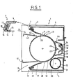
- the development station (1) an embodiment of which is represented in section by a plane perpendicular to the axis of the cylinder (2), comprises a body (3) fixed to a support frame, consisting of two flanges (not shown ) connected by two spacers (4, 5), for example in aluminum profile. Inside the bodywork (3) the development station includes copy drive means and development means.
- the copy drive means consist of a cylinder (2) driven by a rotational movement which cooperates with a fixed mat (6) stretched between two attachment zones (7, 8).
- the cylinder (2) is supported at its ends by the flanges (9) [ Figure 2] provided with cylindrical surfaces (10).
- the cylinder (2) is provided at its ends with end caps (11).
- the end piece (11) is integral with the cylinder (2), it is for example force-fitted or glued, and provided with drive means in rotation of the cylinder (2), these means possibly being a pinion (12).
- a ring (13) can be placed between the end piece (11) and the cylindrical bearing surface (10), for example in polytetrafluoroethylene.
- the ring (13) turns freely relative to the end piece (11) on the one hand, and relative to the cylindrical bearing surface (10) of the flange (9) on the other hand.
- the cylinder (2) can be made of any material provided that it has mechanical properties such that the cylinder (2) is practically non-deformable.
- the surface condition of the cylinder (2) is such that it has sufficient adhesion to cause copying, for this the surface of the cylinder can be provided with a coating.
- an aluminum cylinder provided with a coating of natural, artificial or synthetic rubber is particularly suitable.
- the fixed belt (6) which cooperates with the cylinder (2) is, according to the present embodiment, formed by a plastic sheet, which here is polytetrafluoroethylene.
- the mat is stretched between two attachment zones (7, 8) [see detail] formed by two profiles (14) provided with fixing means (15), such as rivets, at each end of the mat (6).
- the profile (14) also comprises fixing means (16), formed by L -shaped folding of the profile (14), to attachment means provided for this purpose in the structure of the development station. According to the embodiment shown, these attachment means are formed by a groove (18) located between two fins (17) carried by the spacers (4, 5), along their entire length.
- the carpet (6) envelops part of the surface of the cylinder (2), to allow the engagement of a copy between the carpet (6) and the cylinder (2).
- the development station includes means for automatically adjusting the tension of the belt (6).
- These means consist of a flexible blade (19), for example made of rubber, carried by a rod (20) fixed at its ends to the flanges, the flexible blade (19) acting on the face (24) of the mat (6) not in contact with the copy between the attachment profile (14) and the first contact line (21) of the mat (6) and the cylinder (2).
- the development station includes two flexible blade adjustment means (19).
- the means for bringing the copy into contact with the product to reveal the latent image are formed by a channel (22) located on the face (24) of the mat (6) not contact with the copy, the interior space of the channel (22) communicates with the face (25) of the carpet (6) in contact with the copy by means of openings (26) passing through the carpet (6).
- the channel (22) is, of course, provided with tubing (27) for inlet and outlet of the product to reveal the latent image carried by the copy.
- the openings (26) passing through the belt (6) are grouped in a strip placed along a generatrix of the cylinder (2).
- the strip provided with openings (26) is such that its length is equal to the useful width of the development station and its width is between 1 and 20% and preferably between 2 and 15% of the length of the arc of wrapping the cylinder (2) by the mat (6), the wrapping arc being counted between the lines (21) and (28) of contact between the mat (6) and the cylinder (2).
- a point of the copy is in contact with the development product only during its traveling time necessary to cover the width of the strip provided with openings (26) .
- the channel (22) is formed by means of a preformed strip (29) secured, for example by gluing, at the periphery of the strip provided with openings (26) of the carpet.
- the strip may consist of a textile material, for example a glass fabric, coated with a resin, or may consist of a sheet, for example of polytetrafluoroethylene.
- the development station also comprises means for degassing the copy constituted by an area (30) of the mat (6) provided with through openings placed downstream of the channel (22) relative to the direction of movement. of the copy and by suction means (31) located in the vicinity of the area (30) of the carpet (6) provided with openings and acting on the face (24) of the carpet (6) not in contact with the copy .
- the suction means (31) are formed by a hollow cylinder (32) closed at one end and the other end of which is connected to the suction side of a fan.
- the wall of the cylinder (32) is provided with a through opening (33), placed substantially along a generatrix of the cylinder (32) close to the zone (30) provided with openings in the belt (6).
- the opening (33) can be a slot or a plurality of holes.
- suction means allows effective degassing of the copy.
- the means for heating the product and the means for preheating the copy are formed by an electrical resistance (34) associated with a reflector (35) located in the vicinity of the channel (22) arranged in such a way that the reflector (35) directs the heat radiation onto the channel (22) and an area (36) of the face (24) of the mat (6) adjacent to the channel (22) and located in upstream of it.
- the resistor (34) and the reflector (35) are placed inside a screen (37) provided with wings (38) extending as far as the belt (6), this screen (37) has to prevent the other parts of the development station from heating up.
- the resistor (24), the reflector (35) and the screen (37) are fixed to each other by suitable means and are then fixed to a closure panel (39) of the development station, the closure panel (39 ) being for example screwed to the spacers (4) and (5) of the development station.
- the guide (40) preferably comprises a contact (42) which, when activated by the front edge of the copy, controls the supply of the product in the channel (22).
- the contact (42) When the contact (42) is deactivated, after passing the rear edge of the copy, it controls, with a delay, the stopping of the supply of the product in the channel (22).
- a copy bearing a latent image is introduced, guided by the guide (40) between the carpet (6) and the cylinder (2) according to arrow F 4 .
- the supply of product in the channel (22) is controlled.
- the copy is driven between the belt (6) and the cylinder (2), it is preheated during its passage in contact with the area (36) of the mat (6).
- the copy carrying the latent image then reaches the strip provided with openings (26) of the mat (6), the copy is then brought into contact with the product supplied in the channel (22) passing through the openings (26) of the carpet (6), and the latent image becomes visible.
- the copy continues its movement between the belt (6) and the cylinder (2), when it passes in contact with the zone (30) provided with openings, the residual gases on the copy are sucked into the hollow cylinder (32) through the opening (33) and directed to a neutralization station.
- the contact is released and it controls the stopping of the supply of product in the channel (22), the stopping will take place with a certain delay so that all the copy is passed in contact with the strip provided with openings (26) of the carpet (6).
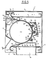
- the development station (1) in section through a plane perpendicular to the cylinder (2), comprises a body (3) fixed to a support frame, consisting of two flanges (not shown ) connected by two spacers (4, 5), for example in aluminum profile. Inside the bodywork (3) the development station includes copy drive means and development means.
- the copy drive means as according to the embodiment shown in Figure 1 are constituted by a cylinder (2) driven in a rotational movement which cooperates with a fixed belt (6) stretched between two attachment zones (7 , 8).
- the fixed belt (6) which cooperates with the cylinder (2) is stretched between two attachment zones (7, 8) formed by two curved sections (14) which cooperate with corresponding curved zones (80) provided on the spacers (4, 5).
- the development station includes means for automatically adjusting the tension of the belt (6).
- These means are constituted by an elastic blade (81), for example made of rubber, interposed between the profile (14) and the end of the mat (6).
- an elastic blade (81) is provided at each end of the mat (6).
- the elastic blade (81) can be fixed on the one hand to the mat (6) and on the other hand to the profile (14) for example by means of rivets.
- the means for bringing the copy into contact with the product to reveal the latent image are formed by two channels (22) located on the face (24) of the mat (6) not in contact with the copy, the interior space of the channels (22) communicates with the face (25) of the mat (6) in contact with the copy by means of openings (26) passing through the mat (6).
- Each channel (22) is, of course, provided with inlet and outlet pipes for the product to reveal the latent image carried by the copy.
- the openings (26) passing through the belt (6) are grouped in a strip placed according to a generatrix of the cylinder (2), to each channel (22) of course corresponds a strip of openings (26).
- the strips provided with openings (26) are such that their length is equal to the useful width of the development station and the sum of their widths is between 1 and 20% and preferably between 2 and 15% of the length of the wrapping arc of the cylinder (2) by the belt (6), the wrapping arc being counted between the lines (21) and (28) of contact between the carpet (6) and the cylinder (2) .
- a point of the copy is in contact with the development product only during its traveling time necessary to traverse the widths of the bands provided openings (26).
- a distributor (45) is placed in the channel (22).
- the distributor (45) occupies substantially the entire interior space of the channel (22), it has the shape of a hollow cylinder provided with an opening (49) in the form of a slot substantially along a generatrix.
- the slot can of course be replaced by several openings, for example by a plurality of small holes, we have generalized in the present text by writing "opening (49)".
- the dispenser (45) is held in place by a strip (82) of textile material, for example glass fabrics, coated with a resin which is secured to the carpet (6), for example by gluing, to form the channel (22 ).
- the same strip (82) of textile material forms the two channels (22) and holds the two distributors (45) in place so that their openings (49) are located at most near the corresponding bands provided with openings (26) of the mat (6).
- Each distributor (45) is connected at its ends to inlet and outlet pipes for the product to reveal the latent image.
- the development station also includes degassing means (96) for the copy constituted by an area (30) of the mat (6) provided with through openings placed downstream of the channels (22) relative to the direction of movement of the copy. and by suction means (31) located in the vicinity of the area (30) provided with openings of the carpet (6) and acting on the face (24) of the carpet (6) not in contact with the copy.
- the suction means consist of a box (83) maintained in depression by connection with the suction side of a fan, the wall of the box has an open area (84) located in the vicinity of the area. (30) provided with belt openings (6).
- the walls (85, 86) of the box limiting the open area (84) extend on either side of the area (30) provided with openings substantially up to the face (24) of the mat (6) not in contact with the copy.
- the development station shown in FIG. 5, comprises downstream means for bringing the copy into contact with the product to reveal the latent image, constituted by the channels (22), recovery means (87) for the unused product.
- the recovery means (87) are of course placed upstream of the degassing means (96) when the development station includes such means.
- the recovery means (87) of the unused product consist of an area (88) of the carpet (6) provided with through openings and collecting means (89) located in the vicinity of the area (88) connected to means suction acting on the face (24) of the carpet (6) not in contact with the copy, the suction means direct the recovered product to the inlet of the channels (22).
- the collection means (89) have a structure similar to that of the means for bringing the copy into contact with the product to reveal the latent image.
- the collection means (89) consist of a collector (90) in the form of a hollow cylinder closed at at least one end and provided with an orifice intended to bring the interior of the cylinder into depression.
- the wall of the manifold (90) is provided with at least one opening (91), such as a slot or a plurality of holes, placed substantially along a generatrix of the cylinder close to the area (88) provided with openings in the mat. (6).
- the collector (90) can be held in place, like the distributor (45), by means of a strip (92) secured to the face (24) of the mat (6) for example by gluing.
- the development station can of course include several recovery means (87).
- a development station as shown may have the distributors (45) and the collector (90) held by the same strip, that is to say that the strip (82) and the strip (92) may be made up of a single piece of textile material.
- the development station includes means for preheating the product to reveal the latent image before the product is fed into the channel (22).
- the preheating means are constituted by a tube (93) for circulation of the product in a round trip connected at one end to the channels (22) and to the other end to the source of product, the tube (93) is located in the vicinity of the channels (22).
- This tube (93) is thus placed in the hottest zone of the development station, that is to say in the zone on which the reflector (35) directs the heat radiation due to the electrical resistance (34) of heating of the product circulating in the channel (22).
- a copy bearing a latent image is introduced, guided by the guide (40) between the carpet (6) and the cylinder (2) according to arrow F 4 .
- the supply of product in the channels (22) is controlled, the product being preheated by passage through the tube (93).
- the copy is driven between the belt (6) and the cylinder (2), it is preheated during its passage in contact with the zone (36) of the mat (6) on which the reflector (35) directs the heat radiation d0 to the electrical resistance (34).
- the copy carrying the latent image then reaches the strips provided with openings (26) of the mat (6), the copy is then brought into contact with the product supplied in the channels (22) passing through the openings (26) of the carpet (6), and the latent image becomes visible.
- the copy continues its movement between the carpet (6) and the cylinder (2), when it passes in contact with the area (88) provided with openings, the product to reveal the latent image which has not been used is sucked through the openings to the recovery means (87) then recycled to the inlet of the channels (22).
- the copy then continues to move between the belt (6) and the cylinder (2), when it passes in contact with the zone (30) provided with openings, the residual gases on the copy are sucked into the box (83) and directed to a neutralization station.
- the rear edge of the copy passes over the contact (42), this is released and it controls the stopping of the supply of product in the channels (22), the stopping will take place with a certain delay so that all the copy is passed in contact with the strips provided with openings (26) of the carpet (6).
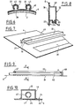
- FIG. 7 shows another embodiment of the mat (6) in which the channel is formed by a section (43) of open section secured by welding to the mat (6).
- the ends of the profile (43) are closed by plugs (44) traversed by the pipes (27) for inlet and outlet of the product.
- Figure 8 shows yet another embodiment of the channel.
- This channel is also formed by a profile (43) of open section which has a shape such that the channel comprises a gutter-forming zone (76) situated at an altitude lower than the altitude of the strip provided with openings in the belt. It has at one end a liquid supply pipe in the gutter and at the other end a gas outlet pipe in the upper part.
- the liquid (77) circulating in the gutter (76) is heated by the heating means as shown in FIG. 1, and generates vapors which pass through the openings (26) of the mat (6) come into contact with the latent image. and the latent image becomes visible.
- the channel (22) has, inside a dispenser (45) of product to reveal the latent image.
- the channel is formed by a profile (46), closed at its ends by two plugs (47, 48), secured, for example by gluing, at the periphery of the strip provided with openings (26) of the belt (6).
- the distributor (45) consists of a hollow cylinder held in place by the plugs (47) and (48), the cylinder passing through the plug (47) is engaged in the plug (48), the plug (48) closing off this end. of the cylinder.
- the cylinder has a slot-shaped opening (49) substantially along a generatrix of the cylinder close to the strip provided with openings (26) of the belt (6).
- the product to reveal the latent image is brought to the distributor (45) by the end of the latter situated on the side of the plug (47), leaves the distributor by the slot (49), in a distribution in the form of a blade and passes through the carpet (6) through the openings (26) to come into contact with the latent image carried by the copy.
- the slot (49) can of course be replaced by a plurality of holes.
- Channels for blade distribution are suitable particularly good when the product to reveal the latent image is gaseous.
- the means for bringing the copy into contact with the product to reveal the latent image shown in FIG. 11 are such that the channel (22) is constituted by a distributor (45) having the shape of a cylinder provided with at least one opening. (49), such as a slot, or a plurality of openings substantially along a generator.
- the distributor (45) is provided with two fins (95) located on either side of the opening (49) intended to secure, for example by gluing, the distributor (45) to the mat (6), in such a way that the opening (49) is located as close as possible to the strip provided with openings (26) of the mat (6).
- two channels (22) as shown in Figure 11 may have a fin (95) placed between the distributors (45) common.
- the collecting means (89) here consist of a collector formed by a section (99) of open section, closed at one end, the other end being connected to suction means.
- the profile can be closed at both ends, it is then provided with a tube passing through its wall.
- the profile (99) is secured to the periphery of the area (88) provided with openings of the carpet (6) on the face (24) thereof not in contact with the copy.
- Figure 13 shows in section another embodiment of the attachment zone (7) of the belt (6) and automatic adjustment means of the tension of the belt (6).
- the attachment zone is formed by a profile (14) having three wings (50, 51, 52), the wings (50) and (51) being substantially parallel.
- the mat (6) is engaged between the parallel wings (50, 51) and the assembly is deformed in a zigzag fashion by crushing between profiled rollers.
- the wing (52) of the profile (14) has holes (54) intended to hooking one end of a spring (55), the other end of the spring (55) being hooked to the wing (17) of the spacer (4) which is provided with holes (56).
- a plurality of springs (55) distributed along the profile (14) constitutes elastic means for automatic adjustment of the tension of the belt (6).
- the reflector (35) according to the embodiment shown in Figure 14 is formed of a metal profile, for example aluminum, in which are provided directly during manufacture, a housing (100) in which will be placed the heating resistor ( 34) and the two conduits (93) intended for the circulation of the product to reveal the latent image before its introduction into the channel (22), circulation thus allowing the preheating of the product.
- the reflector (35) according to this embodiment with two wings (101) extending to the vicinity of the belt (6) in order to avoid heating of the other parts of the development station.
- FIG. 15 An apparatus for reproducing originals comprising a development station according to the invention and as represented in FIG. 1 is represented in FIG. 15.
- the apparatus is of modular design. It comprises a copy paper supply module (57), a module (58) containing an exposure station, and a module (59) containing a development station according to the present invention.
- the copy paper feed module (57) has substantially the shape of a rectangular housing (60) provided with an opening closed by a pivoting cover (61) to place one or more rolls (62) of paper copy in the housing (60).
- the rollers (62) can rotate freely on themselves under the effect of the traction of the copy paper (63), and are, for example, placed on a cradle (64) formed by two cylindrical rods parallel to the axis of the roller (62) and provided with means for immobilizing the roller (62) in translation.
- the upper surface of the housing (61) has a copy paper exit slot (65) and a wire cutter (66).
- the module (58) containing the exposure station comprises, in a housing (67) substantially parallelepipedal provided with an opening (68), an exposure station.
- the exposure station comprises an exposure cylinder (69), inside which is placed a lamp (70) and means for driving the copy and the original around the exposure cylinder (69) .
- the drive means are formed by an endless belt (71) surrounding three rollers (72, 73, 74) at least one of which is rotated, the endless belt (71) enveloping part of the cylinder. exposure (69), and the exposure cylinder (69) being placed in such a way that the part of the belt (71) which envelops it is deflected towards the inside of the prism defined by the axes of the rollers (72, 73 , 74).
- the rollers (72, 73, 74) and possibly the exposure cylinder (69) are supported at their ends by support plates connected to the frame of the module (58).
- the module (59) containing the development station comprises, in a housing (75) substantially parallelepiped, a development station, object of the present invention, similar to that described above and represented in FIG. 1.
- the operator pulls the end of the copy paper (63) and places the original to be reproduced above it. It engages the assembly constituted by the original and the copy paper superimposed according to arrow F 1 between the endless belt (71) and the exposure cylinder (69).
- the latent image is formed on the copy and the assembly leaves the exposure station in the vicinity of the roller (72).
- the operator grasps the front edge of the copy which leaves according to arrow F 2 to separate it from the original, which leaves the exposure station according to arrow F 3 and which is received on the upper surface of the box (60 ) from the paper feed module. It engages the copy carrying the latent image according to arrow F 4 between the carpet (6) and the cylinder (2) of the development module (59).
- the reproduction apparatus has been shown in FIG. 15 with the module containing the development station placed next to the module containing the exposure station, these two modules can of course be one above the other.
- the development station object of the invention, has many advantages.
- the sealing problems are minimized by the design of the development station. Indeed, only the channel is traversed by the product and obtaining its tightness at the periphery of the strip provided with openings is easy to perform since the channel can be obtained either directly with the carpet or by bonding or welding of a strip or a profile at the periphery of the strip provided with openings.
- the development station according to the invention has the advantage of using only small volumes of product. Indeed, on the one hand, the volume of the channel is low and, on the other hand, the product is fed into the channel only for the time necessary for the passage of the copy in the development station.
- the development station object of the invention, is particularly effective during the development of a latent image by ammoniacal vapors.
- the development is all the more effective as the speed of the gas coming into contact with the diazo layer is high, in the present development station, on the one hand, the gas passage section, from the channel to the copy, is low since it is equal to the surface of the openings situated in the strip, and on the other hand, the volume of the channel being small the gas practically does not undergo expansion, it follows that the speed of the gas passing through the openings is high.
- a development station according to the invention which uses a product to reveal the gaseous latent image also has the advantage of being compact.
- the volume of gas used is small, on the one hand, the volume of gas recovered during degassing of the paper is also small, which makes it possible to reduce the size of the neutralization device and the neutralization device does not saturates only slowly, and on the other hand, the frequency of supply of the ammonia vapor generation station is low.
Landscapes
- Physics & Mathematics (AREA)
- General Physics & Mathematics (AREA)
- Photographic Developing Apparatuses (AREA)
- Electrophotography Configuration And Component (AREA)
- Non-Silver Salt Photosensitive Materials And Non-Silver Salt Photography (AREA)
Applications Claiming Priority (4)
| Application Number | Priority Date | Filing Date | Title |
|---|---|---|---|
| FR8513857 | 1985-09-16 | ||
| FR8513857A FR2587508B1 (fr) | 1985-09-16 | 1985-09-16 | Station de developpement et appareil de reproduction d'originaux par diazocopie comportant ladite station |
| FR8607505A FR2599159A2 (fr) | 1986-05-22 | 1986-05-22 | Station de developpement et appareil de reproduction d'originaux par diazocopie comportant ladite station |
| FR8607505 | 1986-05-22 |
Publications (1)
| Publication Number | Publication Date |
|---|---|
| EP0218534A1 true EP0218534A1 (fr) | 1987-04-15 |
Family
ID=26224718
Family Applications (1)
| Application Number | Title | Priority Date | Filing Date |
|---|---|---|---|
| EP86420231A Withdrawn EP0218534A1 (fr) | 1985-09-16 | 1986-09-11 | Station de développement et appareil de reproduction d'originaux par diazocopie comportant ladite station |
Country Status (10)
| Country | Link |
|---|---|
| US (1) | US4772906A (da) |
| EP (1) | EP0218534A1 (da) |
| KR (1) | KR870003406A (da) |
| AU (1) | AU6263686A (da) |
| DK (1) | DK440286A (da) |
| ES (1) | ES2000897A6 (da) |
| FI (1) | FI863711A7 (da) |
| GR (1) | GR862283B (da) |
| NZ (1) | NZ217583A (da) |
| PT (1) | PT83371A (da) |
Cited By (1)
| Publication number | Priority date | Publication date | Assignee | Title |
|---|---|---|---|---|
| FR2633068A1 (fr) * | 1988-06-15 | 1989-12-22 | Regma | Appareil de reproduction d'originaux par diazocopie |
Families Citing this family (2)
| Publication number | Priority date | Publication date | Assignee | Title |
|---|---|---|---|---|
| US5550215A (en) * | 1991-11-22 | 1996-08-27 | Holmes; Christopher P. | Polymer reversal on solid surfaces |
| US6762019B2 (en) * | 1997-09-30 | 2004-07-13 | Surmodics, Inc. | Epoxide polymer surfaces |
Citations (6)
| Publication number | Priority date | Publication date | Assignee | Title |
|---|---|---|---|---|
| GB821031A (en) * | 1956-01-13 | 1959-09-30 | Kelvin & Hughes Ltd | Improvements in and relating to the application of liquid to surfaces |
| DE1135759B (de) * | 1960-05-20 | 1962-08-30 | Dr Marius Boeger | Vorrichtung zur Entwicklung von belichteten Pausen durch Ammoniakgas |
| FR1421713A (fr) * | 1964-12-21 | 1965-12-17 | Kalle Ag | Procédé et dispositif de reproduction de documents |
| FR2358686A1 (fr) * | 1976-07-13 | 1978-02-10 | Cellophane Sa | Procede de developpement a sec d'un materiau de diazotypie et dispositif de mise en oeuvre |
| WO1980002465A1 (en) * | 1979-05-07 | 1980-11-13 | R Hewelt | Method and arrangement for eliminating ammonia vapors from developed diazo copy material |
| DE3232598A1 (de) * | 1982-09-02 | 1984-03-08 | Meteor-Siegen Apparatebau Paul Schmeck Gmbh, 5900 Siegen | Diazokopiermaschine |
Family Cites Families (9)
| Publication number | Priority date | Publication date | Assignee | Title |
|---|---|---|---|---|
| US3122981A (en) * | 1964-03-03 | Gaseous photo-developing apparatus | ||
| US3268694A (en) * | 1964-01-20 | 1966-08-23 | Ranco Inc | Thermostatic control switches |
| US3710708A (en) * | 1971-02-19 | 1973-01-16 | Dietzgen Corp | Exposing and developing apparatus |
| US3915708A (en) * | 1972-07-20 | 1975-10-28 | Norman A Zausmer | Method for developing diazo prints from an external supply source of ammonia and carbon dioxide |
| US4241989A (en) * | 1979-01-15 | 1980-12-30 | Am International, Inc. | Diazo developing apparatus |
| US4371247A (en) * | 1979-05-07 | 1983-02-01 | Robert K. Hewelt | Arrangement for eliminating ammonia vapors from developed diazo copy material |
| US4288155A (en) * | 1979-08-29 | 1981-09-08 | Diazit Company, Inc. | Variable volume diazotype developing apparatus and method |
| US4441803A (en) * | 1982-06-01 | 1984-04-10 | Northwest Blueprint & Supply Co. | Diazo copy machine with ammonia fume eliminator |
| US4582423A (en) * | 1984-09-17 | 1986-04-15 | Blu-Ray Incorporated | Device for degassing diazotype materials by convection heating |
-
1986
- 1986-09-08 GR GR862283A patent/GR862283B/el unknown
- 1986-09-11 EP EP86420231A patent/EP0218534A1/fr not_active Withdrawn
- 1986-09-12 FI FI863711A patent/FI863711A7/fi not_active IP Right Cessation
- 1986-09-12 AU AU62636/86A patent/AU6263686A/en not_active Abandoned
- 1986-09-15 PT PT83371A patent/PT83371A/pt not_active Application Discontinuation
- 1986-09-15 NZ NZ217583A patent/NZ217583A/xx unknown
- 1986-09-15 DK DK440286A patent/DK440286A/da not_active Application Discontinuation
- 1986-09-15 ES ES8601909A patent/ES2000897A6/es not_active Expired
- 1986-09-16 US US06/907,831 patent/US4772906A/en not_active Expired - Fee Related
- 1986-09-16 KR KR1019860007809A patent/KR870003406A/ko not_active Withdrawn
Patent Citations (6)
| Publication number | Priority date | Publication date | Assignee | Title |
|---|---|---|---|---|
| GB821031A (en) * | 1956-01-13 | 1959-09-30 | Kelvin & Hughes Ltd | Improvements in and relating to the application of liquid to surfaces |
| DE1135759B (de) * | 1960-05-20 | 1962-08-30 | Dr Marius Boeger | Vorrichtung zur Entwicklung von belichteten Pausen durch Ammoniakgas |
| FR1421713A (fr) * | 1964-12-21 | 1965-12-17 | Kalle Ag | Procédé et dispositif de reproduction de documents |
| FR2358686A1 (fr) * | 1976-07-13 | 1978-02-10 | Cellophane Sa | Procede de developpement a sec d'un materiau de diazotypie et dispositif de mise en oeuvre |
| WO1980002465A1 (en) * | 1979-05-07 | 1980-11-13 | R Hewelt | Method and arrangement for eliminating ammonia vapors from developed diazo copy material |
| DE3232598A1 (de) * | 1982-09-02 | 1984-03-08 | Meteor-Siegen Apparatebau Paul Schmeck Gmbh, 5900 Siegen | Diazokopiermaschine |
Cited By (1)
| Publication number | Priority date | Publication date | Assignee | Title |
|---|---|---|---|---|
| FR2633068A1 (fr) * | 1988-06-15 | 1989-12-22 | Regma | Appareil de reproduction d'originaux par diazocopie |
Also Published As
| Publication number | Publication date |
|---|---|
| AU6263686A (en) | 1987-03-19 |
| FI863711A0 (fi) | 1986-09-12 |
| DK440286A (da) | 1987-03-17 |
| DK440286D0 (da) | 1986-09-15 |
| NZ217583A (en) | 1989-01-27 |
| ES2000897A6 (es) | 1988-03-16 |
| KR870003406A (ko) | 1987-04-17 |
| GR862283B (en) | 1987-01-12 |
| US4772906A (en) | 1988-09-20 |
| PT83371A (pt) | 1987-05-06 |
| FI863711A7 (fi) | 1987-03-17 |
Similar Documents
| Publication | Publication Date | Title |
|---|---|---|
| EP1123194B1 (fr) | Procede de fabrication d'un corps de revolution creux, corps tel qu'obtenu par ledit procede, et dispositif de mise en oeuvre dudit procede | |
| WO2001079644A1 (fr) | Vitrage isolant et son procede de fabrication | |
| FR2523936A1 (fr) | Ensemble compact de barres a air pour le support sans contact d'une piece ou bande de papier | |
| FR2475510A1 (fr) | Guide sans contact pour feuille continue lors d'un changement de direction | |
| FR2589611A1 (fr) | Rouleau pour appliquer un solvant sur des etiquettes en plastique | |
| WO2003040507A1 (fr) | Vitrage isolant et son procede de fabrication | |
| EP0218534A1 (fr) | Station de développement et appareil de reproduction d'originaux par diazocopie comportant ladite station | |
| FR2532732A1 (fr) | Dispositif pour secher et guider une piece ou bande | |
| FR2587508A1 (fr) | Station de developpement et appareil de reproduction d'originaux par diazocopie comportant ladite station | |
| EP0280628A1 (fr) | Appareil de reproduction d'originaux par diazocopie | |
| WO2008152309A1 (fr) | Machine d'impression et procédé correspondant | |
| FR2633068A1 (fr) | Appareil de reproduction d'originaux par diazocopie | |
| EP0282420A1 (fr) | Appareil de reproduction d'originaux par diazocopie | |
| EP0029792A1 (fr) | Dispositif pour réaliser en continu le revêtement de la surface externe d'un profilé | |
| FR2599159A2 (fr) | Station de developpement et appareil de reproduction d'originaux par diazocopie comportant ladite station | |
| FR2530837A1 (fr) | Dispositif pour retirer les particules de revelateur en exces sur la surface d'un element d'enregistrement | |
| EP2842637B1 (fr) | Machine et procédé d'enduction à barrière fluidique | |
| EP1576630B1 (fr) | Dispositif de realisation d'ensemble de stockage d'energie electrique par enroulement sur mandrin plat | |
| EP0562142B1 (fr) | Poche à vide pour la fabrication de verre de sécurité | |
| CH629701A5 (fr) | Appareil pour la fabrication de sacs en matiere plastique. | |
| BE494199A (da) | ||
| EP0006799B1 (fr) | Procédé pour améliorer la vitesse de développement dans les machines de diazocopie et dispositif pour la mise en oeuvre | |
| FR2792231A1 (fr) | Materiau de garnissage | |
| FR2467636A1 (fr) | Machine a enduire et recouvrir des profiles et/ou des planches | |
| JP3574224B2 (ja) | 画像形成用溶媒塗布装置 |
Legal Events
| Date | Code | Title | Description |
|---|---|---|---|
| PUAI | Public reference made under article 153(3) epc to a published international application that has entered the european phase |
Free format text: ORIGINAL CODE: 0009012 |
|
| AK | Designated contracting states |
Kind code of ref document: A1 Designated state(s): AT BE CH DE FR GB IT LI LU NL SE |
|
| 17P | Request for examination filed |
Effective date: 19870619 |
|
| 17Q | First examination report despatched |
Effective date: 19890421 |
|
| STAA | Information on the status of an ep patent application or granted ep patent |
Free format text: STATUS: THE APPLICATION IS DEEMED TO BE WITHDRAWN |
|
| 18D | Application deemed to be withdrawn |
Effective date: 19890902 |
|
| RIN1 | Information on inventor provided before grant (corrected) |
Inventor name: LEROUX, JEAN-CLAUDE Inventor name: CROSNIER, DANIEL |