EP0218545A2 - Crystallisation apparatus and its use - Google Patents
Crystallisation apparatus and its use Download PDFInfo
- Publication number
- EP0218545A2 EP0218545A2 EP86810363A EP86810363A EP0218545A2 EP 0218545 A2 EP0218545 A2 EP 0218545A2 EP 86810363 A EP86810363 A EP 86810363A EP 86810363 A EP86810363 A EP 86810363A EP 0218545 A2 EP0218545 A2 EP 0218545A2
- Authority
- EP
- European Patent Office
- Prior art keywords
- internals
- crystallization device
- tube
- effective surface
- surface area
- Prior art date
- Legal status (The legal status is an assumption and is not a legal conclusion. Google has not performed a legal analysis and makes no representation as to the accuracy of the status listed.)
- Granted
Links
Images



Classifications
-
- B—PERFORMING OPERATIONS; TRANSPORTING
- B01—PHYSICAL OR CHEMICAL PROCESSES OR APPARATUS IN GENERAL
- B01D—SEPARATION
- B01D9/00—Crystallisation
- B01D9/0004—Crystallisation cooling by heat exchange
- B01D9/0013—Crystallisation cooling by heat exchange by indirect heat exchange
Definitions
- the invention relates to a crystallization device with at least one tube which can be charged with the liquid mixture to be treated.
- CH-PS 50l 42l describes a method and a device for separating substances from a liquid mixture by fractional crystallization.
- This process has become known as the "Sulzer MWB" process. It essentially consists in repeatedly passing the liquid mixture through a crystallization device, the deposited crystal layer being melted off after a certain thickness has been reached.
- the crystallization device has a vertically arranged tube bundle, in which the liquid mixture is passed through the tubes, which are flushed outside by a heat transfer medium which has the temperature necessary for the crystallization.
- a disadvantage of this crystallization device is that the heat transfer deteriorates considerably with the growth of the crystallized layer on the tube wall. This also reduces the efficiency of the process. With certain materials, the beginning of crystallization also presents problems, ie the triggering of the crystal layer formation is often not reproducible.
- an increase in the efficiency of the crystallization process should be achieved, e.g. by reducing the number of pipes required for the same system capacity.
- a large pipe load should also be possible, even with materials that adhere relatively poorly to the pipe wall.
- the invention provides internals which increase the effective surface area inside the tube. Since the heat dissipation by the coolant is a limiting factor for the kinetics of crystal formation, the amount of crystal produced per unit length of the tube is not significantly increased by the use of internals, but a lower linear growth rate is obtained on the crystal surface and this leads to better ones Conditions for the formation of pure crystals. For example, the concentration of impurities at the boundary layer of the crystals is largely avoided.
- the internals enable a large pipe load even with poorly adhering crystals.
- An exemplary embodiment of the invention provides that different internals are provided in succession in the respective tube and that, when viewed in the direction of flow, the effective surface area per unit length of the subsequent internals is greater than that of the preceding internals.
- the internals expediently have structural elements projecting inwards from the tube wall. This design has the advantage that even when the tube is largely filled with crystals, heat is transferred through the highly conductive structural elements. It is expedient if the internals in the area of the tube wall have contact surfaces designed for heat transfer.
- the internals are advantageously provided with perforations. These can be designed according to the purpose. Perforations improve the liquid distribution at the start of crystallization and enable a large tube load. Instead of perforations or additionally perforations, the internals can also have a surface structure, for example a corrugation. This also brings similar advantages as the perforations.
- the internals can consist of sheet metal. Such training is particularly inexpensive to manufacture. A particularly simple type of internals consists of a multiply folded metal sheet.
- the invention also relates to the use of the crystallization device for carrying out the "Sulzer MWB" process.
- the crystallization device 11 forms the most important part of the plant.
- the fractions from the collecting tank l9 are temporarily stored in tanks l3, l5, l7.
- the production cycle takes place via the pump 2l.
- the valves 23 to 25 serve as the inlet or outlet of the tanks l3, l5 and l7. Coolant or heating medium are transferred to the crystallization device 11 by means of the pump 27 the heat exchanger 29 supplied.
- the crystallizate can be discharged via the valve 3l and the mother liquor via the valve 33.
- the crystallization process is controlled by a fully automatic control device 35. A detailed description of the process can be found in CH-PS 50l 42l.
- the crystallization device II which is not shown in detail in FIG. 1, has a tube bundle, the tubes of which can be fed with a trickle film or a full tube flow of the liquid mixture to be treated.
- the invention provides that the tubes 4l have built-in elements 43 which increase the effective surface area inside the tube.
- the internals 43 have three different sections 45, 46 and 47. Section 46 has a larger effective surface area than section 45. Section 47 in turn has a larger effective surface area than section 46.
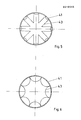
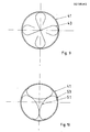
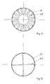
- the internals can have different configurations depending on the liquid mixture to be treated, as shown, for example, in FIGS. 3 to 12 becomes. It is important that the internals have structural elements 5l projecting inwards from the tube wall 4l, which ensure heat transfer, even if a relatively thick crystal layer is already present. It is advantageous if the internals 43 have special contact surfaces 53 designed for heat transfer, which contact the tube wall 4l.
- the internals can have perforations 54.
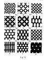
- Figures l3a to m show possible exemplary embodiments for such perforations 54.
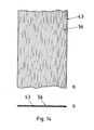
- a surface structuring e.g. a corrugation 56 may be provided, as is shown, for example, in FIGS. 14a and b.
- the main material used for the internals is sheet metal, e.g. stainless steel, in question.
- the metal sheet can be corrugated or folded in various ways. A corrugation as shown in FIG. 3 is particularly suitable.
Landscapes
- Physics & Mathematics (AREA)
- Thermal Sciences (AREA)
- Chemical & Material Sciences (AREA)
- Crystallography & Structural Chemistry (AREA)
- Chemical Kinetics & Catalysis (AREA)
- Vaporization, Distillation, Condensation, Sublimation, And Cold Traps (AREA)
- Heat-Exchange Devices With Radiators And Conduit Assemblies (AREA)
- Physical Or Chemical Processes And Apparatus (AREA)
Abstract
Im Rohr (4l) eines Rohrbündels der Kristallisationsvorrichtung ist eine Einbaute (43) vorgesehen, welche die wirksame Oberfläche im Innern des Rohrs (4l) vergrössert. Die Einbaute weist nacheinander verschiedene Abschnitte (45, 46, 47) auf, wobei in Flussrichtung gesehen die wirksame Oberfläche pro Längeneinheit des nachfolgenden Abschnitts (46, 47) grösser ist als die wirksame Oberfläche des vorangehenden Abschnitts (45, 46). Da die Wärmeabfuhr durch das Kühlmittel ein limitierender Faktor für die Kinetik der Kristallbildung darstellt, wird die pro Längeneinheit des Rohrs erzeugte Kristallmenge durch den Einsatz der Einbauten zwar nicht wesentlich vergrössert, aber es wird eine kleinere lineare Wachstumsgeschwindigkeit an der Kristalloberfläche erreicht und dies führt zu besseren Bedingungen für die Bildung eines reineren Kristallisats. 
Description
Die Erfindung betrifft eine Kristallisationsvorrichtung mit mindestens einem Rohr, das mit dem zu behandelnden Flüssigkeitsgemisch beschickbar ist.The invention relates to a crystallization device with at least one tube which can be charged with the liquid mixture to be treated.
Die CH-PS 50l 42l beschreibt ein Verfahren und eine Vorrichtung zur Stofftrennung aus einem flüssigen Gemisch durch fraktionierte Kristallisation. Dieses Verfahren ist als "Sulzer-MWB"-Verfahren bekannt geworden. Es besteht im wesentlichen darin, dass das flüssige Gemisch wiederholt durch eine Kristallisationsvorrichtung geführt wird, wobei die abgeschiedene Kristallschicht nach Erreichen einer bestimmten Dicke abgeschmolzen wird. Die Kristallisationsvorrichtung weist ein senkrecht angeordnetes Rohrbündel auf, bei dem das Flüssigkeitsgemisch durch die Rohre geführt wird, welche aussen von einem Wärmeübertragungsmittel umspült werden, das die für die Kristallisation notwendige Temperatur aufweist. Bei dieser Kristallisationsvorrichtung ist nachteilig, dass sich der Wärmeübergang mit dem Anwachsen der auskristallisierten Schicht an der Rohrwandung erheblich verschlechtert. Dadurch verschlechtert sich auch der Wirkungsgrad des Verfahrens. Bei gewissen Materialien bietet auch der Beginn der Kristallisation Probleme, d.h. die Auslösung der Kristallschichtbildung ist vielfach nicht reproduzierbar.CH-PS 50l 42l describes a method and a device for separating substances from a liquid mixture by fractional crystallization. This process has become known as the "Sulzer MWB" process. It essentially consists in repeatedly passing the liquid mixture through a crystallization device, the deposited crystal layer being melted off after a certain thickness has been reached. The crystallization device has a vertically arranged tube bundle, in which the liquid mixture is passed through the tubes, which are flushed outside by a heat transfer medium which has the temperature necessary for the crystallization. A disadvantage of this crystallization device is that the heat transfer deteriorates considerably with the growth of the crystallized layer on the tube wall. This also reduces the efficiency of the process. With certain materials, the beginning of crystallization also presents problems, ie the triggering of the crystal layer formation is often not reproducible.
Es ist Aufgabe der vorliegenden Erfindung, eine Kristallisationsvorrichtung der eingangs erwähnten Art zu verbessern, um die genannten Nachteile ganz oder mindestens zum Teil zu vermeiden. Insbesondere sollte eine Erhöhung des Wirkungsgrades des Kristallisationsverfahrens erzielt werden, z.B. durch Reduzierung der Anzahl der notwendigen Rohre bei gleicher Kapazität der Anlage. Auch sollte eine grosse Rohrbeladung möglich sein, und zwar auch bei Materialien, die relativ schlecht an der Rohrwandung haften.It is an object of the present invention to improve a crystallization device of the type mentioned in the introduction in order to avoid the disadvantages mentioned, in whole or in part. In particular, an increase in the efficiency of the crystallization process should be achieved, e.g. by reducing the number of pipes required for the same system capacity. A large pipe load should also be possible, even with materials that adhere relatively poorly to the pipe wall.
Zur Lösung dieser Aufgabe sieht die Erfindung Einbauten vor, welche die wirksame Oeberfläche im Innern des Rohrs vergrössern. Da die Wärmeabfuhr durch das Kühlmittel ein limitierender Faktor für die Kinetik der Kristallbildung darstellt, wird die pro Längeneinheit des Rohres erzeugte Kristallmenge durch den Einsatz von Einbauten zwar nicht wesentlich vergrössert, aber es wird eine kleinere lineare Wachstumsgeschwindigkeit an der Kristalloberfläche erhalten und dies führt zu besseren Bedingungen für die Bildung eines reinen Kristallisats. So wird beispielsweise die Aufkonzentrierung der Verunreinigungen an der Grenzschicht der Kristalle weitgehend vermieden. Die Einbauten ermöglichen auch bei schlecht haftendem Kristallisat eine grosse Rohrbeladung.To achieve this object, the invention provides internals which increase the effective surface area inside the tube. Since the heat dissipation by the coolant is a limiting factor for the kinetics of crystal formation, the amount of crystal produced per unit length of the tube is not significantly increased by the use of internals, but a lower linear growth rate is obtained on the crystal surface and this leads to better ones Conditions for the formation of pure crystals. For example, the concentration of impurities at the boundary layer of the crystals is largely avoided. The internals enable a large pipe load even with poorly adhering crystals.
Ein Ausführungsbeispiel der Erfindung sieht vor, dass im jeweiligen Rohr nacheinander verschiedene Einbauten vorgesehen sind und dass in Flussrichtung gesehen die wirksame Oberfläche pro Längeneinheit der nachfolgenden Einbaute grösser ist als jene der vorangehenden Einbaute. Dies hat den Vorteil, dass keine Ueberhitzung der zu kristallisierenden Masse im oberen Teil des Rohres erfolgen muss, um eine konstitutionelle Unterkühlung zu verhindern. Durch die progressive Vergrösserung der Oberfläche von Einbaute zu Einbaute wird ferner die Haftung des Kristallisats weiter verbessert, was wiederum eine Erhöhung der Rohrbeladung ermöglicht.An exemplary embodiment of the invention provides that different internals are provided in succession in the respective tube and that, when viewed in the direction of flow, the effective surface area per unit length of the subsequent internals is greater than that of the preceding internals. This has the advantage that there is no need to overheat the mass to be crystallized in the upper part of the tube in order to to prevent constitutional hypothermia. The progressive enlargement of the surface from built-in to built-in further improves the adhesion of the crystals, which in turn enables the pipe load to be increased.
Zweckmässigerweise weisen die Einbauten.von der Rohrwandung nach innen ragende Strukturelement auf. Diese Ausbildung hat den Vorteil, dass auch bei weitgehender Füllung des Rohrs durch Kristallisat eine Wärmeübertragung durch die gut leitenden Strukturelemente erfolgt. Dabei ist zweckmässig, wenn die Einbauten im Bereich der Rohrwandung für den Wärmeübergang ausgebildete Kontaktflächen aufweisen. Vorteilhaft sind die Einbauten mit Perforationen versehen. Diese können dem Zweck entsprechend ausgebildet sein. So verbessern Perforationen die Flüssigkeitsverteilung zu Beginn der Kristallisation und ermöglichen eine grosse Rohrbeladung. Anstelle von Perforationen oder zusätzlich von Perforationen können die Einbauten auch eine Oberflächenstrukturierung, z.B. eine Riffelung aufweisen. Auch dies bringt ähnliche Vorteile wie die Perforationen. Die Einbauten können aus Metallblech bestehen. Eine solche Ausbildung ist besonders kostengünstig in der Herstellung. Eine besonders einfache Art von Einbauten besteht aus einem mehrfach gefalteten Metallblech. Dadurch entsteht im Schnitt z.B. eine sternförmige Anordnung. Dies hat den Vorteil, dass im Bereich der Rohrwandung eine Kapillarwirkung in den Falten entsteht. Dadurch wird die Fliessgeschwindigkeit des Flüssigkeitsgemisches verlangsamt, so dass es sich lokal stärker abkühlt und dadurch die Auslösung des Kristallisationsvorgangs erleichtert. Wenn korrosive Flüssigkeitsgemische behandelt werden müssen, können auch Einbauten aus Kunststoff, z.B. Polyvinylchlorid oder aus Graphit verwendet werden.The internals expediently have structural elements projecting inwards from the tube wall. This design has the advantage that even when the tube is largely filled with crystals, heat is transferred through the highly conductive structural elements. It is expedient if the internals in the area of the tube wall have contact surfaces designed for heat transfer. The internals are advantageously provided with perforations. These can be designed according to the purpose. Perforations improve the liquid distribution at the start of crystallization and enable a large tube load. Instead of perforations or additionally perforations, the internals can also have a surface structure, for example a corrugation. This also brings similar advantages as the perforations. The internals can consist of sheet metal. Such training is particularly inexpensive to manufacture. A particularly simple type of internals consists of a multiply folded metal sheet. This creates, for example, a star-shaped arrangement on average. This has the advantage that a capillary effect occurs in the folds in the area of the tube wall. This slows down the flow rate of the liquid mixture so that it cools down more locally, thereby facilitating the initiation of the crystallization process. If corrosive liquid mixtures have to be treated, internals made of plastic, for example polyvinyl chloride or graphite, can also be used.
Die Erfindung betrifft auch die Verwendung der Kristallisationsvorrichtung zur Durchführung des "Sulzer-MWB"-Verfahrens.The invention also relates to the use of the crystallization device for carrying out the "Sulzer MWB" process.
Ausführungsbeispiele der Erfindung werden nun unter Bezugnahme auf die Zeichnung beschrieben. Es zeigt:
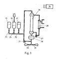
- Fig. l eine schematische Darstellung einer Anlage zur Durchführung des bekannten Sulzer-MWB-Verfahrens,
- Fig. 2 einen Ausschnitt aus einer Kristallisationsvorrichtung,
- Fig. 3 bis l2
verschiedene Ausführungsformen der Einbauten im Querschnitt, - Fig. l3 verschiedene Ausführungsformen von perforiertem Material für die Einbauten,
- Fig. l4a und b
ein Ausführungsbeispiel eines Blechstreifens mit einer Riffelung als Oberflächenstrukturierung.
- 1 shows a schematic representation of a plant for carrying out the known Sulzer MWB process,
- 2 shows a section of a crystallization device,
- 3 to l2
different embodiments of the internals in cross section, - L3 different embodiments of perforated material for the internals,
- Fig. L4a and b
an embodiment of a sheet metal strip with a corrugation as a surface structure.
Bei der Anlage gemäss Figur l zur Durchführung des SulzerMWB-Kristallisationsverfahren bildet die Kristallisationsvorrichtung ll den wesentlichsten Anlageteil. In den Tanks l3, l5, l7 werden die Fraktionen aus dem Sammeltank l9 zwischengelagert. Der Produktionskreislauf erfolgt über die Pumpe 2l. Die Ventile 23 bis 25 dienen als Einlass oder Auslass der Tanks l3, l5 und l7. Kühl- oder Heizmittel werden der Kristallisationsvorrichtung ll mittels der Pumpe 27 über den Wärmetauscher 29 zugeführt. Nach der Durchführung der verschiedenen Kristallisationszyklen kann das Kristallisat über das Ventil 3l und die Mutterlauge über das Ventil 33 abgelassen werden. Die Steuerung des Kristallisationsverfahrens erfolgt durch eine vollautomatische Steuerungseinrichtung 35. Eine detaillierte Beschreibung des Verfahrens findet sich in der CH-PS 50l 42l.In the plant according to FIG. 1 for carrying out the SulzerMWB crystallization process, the
Die in Figur l nicht in Details dargestellte Kristallisationsvorrichtung ll weist ein Rohrbündel auf, dessen Rohre mit einem Rieselfilm oder einer vollen Rohrströmung des zu behandelnden Flüssigkeitsgemisches beschickbar sind.The crystallization device II, which is not shown in detail in FIG. 1, has a tube bundle, the tubes of which can be fed with a trickle film or a full tube flow of the liquid mixture to be treated.
Wie Figur 2 zeigt, sieht die Erfindung im Gegensatz zum bekannten Stand der Technik vor, dass die Rohre 4l Einbauten 43 aufweisen, welche die wirksame Oberfläche im Innern des Rohres vergrössern. Bei dem in Figur 2 gezeigten Ausführungsbeispiel weisen die Einbauten 43 drei verschiedene Abschnitte 45, 46 und 47 auf. Der Abschnitt 46 hat eine grössere wirksame Oberfläche als der Abschnitt 45. Der Abschnitt 47 wiederum hat eine grössere wirksame Oberfläche als der Abschnitt 46. Die Einbauten können je nach dem zu behandelnden Flüssigkeitsgemisch verschiedene Ausgestaltungen haben, wie dies beispielsweise in den Figuren 3 bis l2 dargestellt wird. Wichtig ist dabei, dass die Einbauten von der Rohrwandung 4l her nach innen ragende Strukturelemente 5l aufweisen, welche für einen Wärmeübergang sorgen, auch wenn bereits eine relativ dicke Kristallschicht vorhanden ist. Es ist dabei von Vorteil, wenn die Einbauten 43 spezielle für den Wärmeübergang ausgebildete Kontaktflächen 53 aufweisen, welche an der Rohrwandung 4l anliegen. Die Einbauten können Perforationen 54 aufweisen.As shown in FIG. 2, in contrast to the known state of the art, the invention provides that the tubes 4l have built-in
Die Figuren l3a bis m zeigen mögliche Ausführungsbeispiele für solche Perforationen 54. Statt Perforationen oder zusätzlich zu Perforationen kann auch eine Oberflächenstrukturierung, z.B. eine Riffelung 56, vorgesehen sein, wie dies in den Figuren l4a und b beispielsweise dargestellt wird.Figures l3a to m show possible exemplary embodiments for
Als Material für die Einbauten kommt in erster Linie Metallblech, z.B. rostfreier Stahl, in Frage. Wie die Figuren 3 bis l2 zeigen, kann das Metallblech auf verschiedene Weise gewellt oder gefaltet sein. Speziell gut eignet sich eine Wellung, wie sie in Figur 3 dargestellt ist.The main material used for the internals is sheet metal, e.g. stainless steel, in question. As shown in FIGS. 3 to 12, the metal sheet can be corrugated or folded in various ways. A corrugation as shown in FIG. 3 is particularly suitable.
Für die Behandlung von gewissen Flüssigkeitsgemischen, z.B. korrosiven Flüssigkeitsgemischen, können auch Einbauten aus einem nichtmetallischen Material, z.B. Graphit, Polyvinylchlorid, verwendet werden. Diese Einbauten sollten eine bessere Wärmeleitfähigkeit aufweisen als das Kristallisat.For the treatment of certain liquid mixtures, e.g. corrosive liquid mixtures, also internals made of a non-metallic material, e.g. Graphite, polyvinyl chloride can be used. These internals should have better thermal conductivity than the crystals.
Claims (11)
Applications Claiming Priority (2)
| Application Number | Priority Date | Filing Date | Title |
|---|---|---|---|
| CH4359/85 | 1985-10-09 | ||
| CH4359/85A CH667816A5 (en) | 1985-10-09 | 1985-10-09 | CRYSTALIZATION DEVICE AND THEIR USE. |
Publications (3)
| Publication Number | Publication Date |
|---|---|
| EP0218545A2 true EP0218545A2 (en) | 1987-04-15 |
| EP0218545A3 EP0218545A3 (en) | 1987-09-02 |
| EP0218545B1 EP0218545B1 (en) | 1990-10-31 |
Family
ID=4274630
Family Applications (1)
| Application Number | Title | Priority Date | Filing Date |
|---|---|---|---|
| EP86810363A Expired - Lifetime EP0218545B1 (en) | 1985-10-09 | 1986-08-15 | Crystallisation apparatus and its use |
Country Status (5)
| Country | Link |
|---|---|
| US (1) | US4776177A (en) |
| EP (1) | EP0218545B1 (en) |
| JP (1) | JPS6287202A (en) |
| CH (1) | CH667816A5 (en) |
| DE (1) | DE3675320D1 (en) |
Cited By (9)
| Publication number | Priority date | Publication date | Assignee | Title |
|---|---|---|---|---|
| EP0687666A1 (en) | 1994-06-15 | 1995-12-20 | Bayer Ag | Process for purifying diphenyle carbonate |
| US5510499A (en) * | 1993-07-26 | 1996-04-23 | Bayer Aktiengesellschaft | Process for the isolation of purified ethylene glycol carbonate (EGC) |
| EP0784046A1 (en) | 1996-01-12 | 1997-07-16 | Basf Aktiengesellschaft | Process for production of acrylic acid and their esters |
| US5824816A (en) * | 1996-04-09 | 1998-10-20 | Bayer Ag | Recovery of catalyst systems from diarylcarbonate-containing reaction mixtures by melt crystallization |
| EP0891798A1 (en) * | 1997-07-16 | 1999-01-20 | Sulzer Chemtech AG | Process for fractionated crystallising substances, crystallizer siuted to perform the process and use of the crystallizer |
| US7129376B2 (en) | 2001-05-10 | 2006-10-31 | Basf Aktiengesellschaft | Method for the production of a purified melt of at least one monomer |
| CN103673603A (en) * | 2012-09-26 | 2014-03-26 | 中国石油大学(北京) | Heating furnace radiation furnace tube with lining arranged in staggered mode |
| EP3384981A1 (en) * | 2017-04-07 | 2018-10-10 | Schmidt + Clemens GmbH & Co. KG | Tube and device for the thermal splitting of hydrocarbons |
| WO2018185167A1 (en) * | 2017-04-07 | 2018-10-11 | Schmidt + Clemens Gmbh + Co. Kg | Pipe and device for thermally cleaving hydrocarbons |
Families Citing this family (11)
| Publication number | Priority date | Publication date | Assignee | Title |
|---|---|---|---|---|
| US5161959A (en) * | 1991-03-11 | 1992-11-10 | Ford Motor Company | Viscosity sensitive hydraulic pump flow control |
| JP3001181B2 (en) * | 1994-07-11 | 2000-01-24 | 株式会社クボタ | Reaction tube for ethylene production |
| DE19536792A1 (en) * | 1995-10-02 | 1997-04-03 | Basf Ag | Process for the separation of substances from a liquid mixture by crystallization |
| DE19845336A1 (en) * | 1998-10-01 | 2000-04-06 | Behr Gmbh & Co | Multi-channel flat tube |
| DE10122788A1 (en) * | 2001-05-10 | 2002-06-06 | Basf Ag | Preparation of purified melt of monomer(s) involves forming suspension, crystallizing, mechanically separating suspended monomer crystals and further crystallizing and separating |
| US7008544B2 (en) * | 2002-05-08 | 2006-03-07 | Marine Desalination Systems, L.L.C. | Hydrate-based desalination/purification using permeable support member |
| US20090260789A1 (en) * | 2008-04-21 | 2009-10-22 | Dana Canada Corporation | Heat exchanger with expanded metal turbulizer |
| RU2461405C2 (en) * | 2010-03-23 | 2012-09-20 | ООО "Фторидные технологии" | Apparatus for extracting crystals from solutions |
| FR2998806B1 (en) * | 2012-12-03 | 2017-10-27 | Arkema France | PROCESS FOR PURIFICATION BY FRACTIONAL CRYSTALLIZATION IN A MELT MEDIUM ON TEXTURED SURFACES |
| TWM458497U (en) * | 2013-04-08 | 2013-08-01 | guo-zhen Cai | Water hammer cancellation device |
| EP4327907A1 (en) * | 2022-08-25 | 2024-02-28 | ERK Eckrohrkessel GmbH | Method and device for obtaining at least one inorganic valuable substance |
Family Cites Families (19)
| Publication number | Priority date | Publication date | Assignee | Title |
|---|---|---|---|---|
| CA448458A (en) * | 1948-05-11 | T. Elder Frederick | Heat exchanger fin-tube | |
| BE516278A (en) * | ||||
| NL289237A (en) * | ||||
| FR494525A (en) * | 1917-04-03 | 1919-09-11 | Charles Cuau | Improvements in the construction of radiators intended for cooling the circulating water of internal combustion engines |
| GB425376A (en) * | 1933-11-03 | 1935-03-13 | Dewandre Co Ltd C | Improvements in or relating to heat transmitting tubes |
| GB491870A (en) * | 1937-03-11 | 1938-09-12 | Norman Isherwood | Radiators or water cooling apparatus for use in connection with the internal combustion engines of motor road vehicles and for like apparatus |
| FR1052023A (en) * | 1951-03-05 | 1954-01-20 | Otto Sau Rebau U Keramikwerke | Improvements to processes and devices for crystallizing salts, obtained by cooling hot concentrates, more especially sulphate defer from caustic lye |
| US2874199A (en) * | 1954-12-22 | 1959-02-17 | Phillips Petroleum Co | Fractional crystallization process and apparatus |
| FR1350756A (en) * | 1962-12-17 | 1964-01-31 | Internal finned tube for temperature exchangers | |
| FR1362784A (en) * | 1963-06-14 | 1964-06-05 | American Radiator & Standard | Heat exchanger tube |
| AT279547B (en) * | 1967-04-14 | 1970-03-10 | Buchs Metallwerk Ag | Method and device for separating or purifying molten, liquid or dissolved substances by fractional crystallization |
| US3528786A (en) * | 1969-09-05 | 1970-09-15 | United States Steel Corp | Production of sodium silicofluoride from wet process phosphoric acid |
| JPS4734356U (en) * | 1971-05-11 | 1972-12-16 | ||
| US3891394A (en) * | 1974-04-10 | 1975-06-24 | Love Oil Company Inc | Crystal generator to inhibit scale formation and corrosion in fluid handling systems |
| JPS5249859A (en) * | 1975-10-17 | 1977-04-21 | Kosaka Kenkyusho:Kk | Device for measuring shape using electrical correction |
| JPS5351539A (en) * | 1976-10-21 | 1978-05-11 | Matsushita Electric Ind Co Ltd | Heat exchanger |
| JPS54147846U (en) * | 1978-04-07 | 1979-10-15 | ||
| IT1119287B (en) * | 1979-06-20 | 1986-03-10 | Fiat Ricerche | PROCEDURE FOR THE PREPARATION OF A MIXTURE INCLUDING A SOLID PHASE AND A LIQUID PHASE OF A METAL ALLOY AND DEVICE SUITABLE TO CARRY OUT SUCH PROCEDURE |
| DE3317537A1 (en) * | 1983-05-11 | 1984-11-15 | Schering AG, 1000 Berlin und 4709 Bergkamen | CRYSTALIZATION SEPARATOR AND METHOD FOR SEPARATING MIXTURES |
-
1985
- 1985-10-09 CH CH4359/85A patent/CH667816A5/en not_active IP Right Cessation
-
1986
- 1986-08-15 DE DE8686810363T patent/DE3675320D1/en not_active Expired - Lifetime
- 1986-08-15 EP EP86810363A patent/EP0218545B1/en not_active Expired - Lifetime
- 1986-09-29 US US06/913,341 patent/US4776177A/en not_active Expired - Fee Related
- 1986-10-03 JP JP61236059A patent/JPS6287202A/en active Granted
Cited By (15)
| Publication number | Priority date | Publication date | Assignee | Title |
|---|---|---|---|---|
| US5510499A (en) * | 1993-07-26 | 1996-04-23 | Bayer Aktiengesellschaft | Process for the isolation of purified ethylene glycol carbonate (EGC) |
| EP0687666A1 (en) | 1994-06-15 | 1995-12-20 | Bayer Ag | Process for purifying diphenyle carbonate |
| US5495038A (en) * | 1994-06-15 | 1996-02-27 | Bayer Aktiengesellschaft | Process for the purification of diphenyl carbonate |
| EP0784046A1 (en) | 1996-01-12 | 1997-07-16 | Basf Aktiengesellschaft | Process for production of acrylic acid and their esters |
| US5824816A (en) * | 1996-04-09 | 1998-10-20 | Bayer Ag | Recovery of catalyst systems from diarylcarbonate-containing reaction mixtures by melt crystallization |
| US6145340A (en) * | 1997-07-16 | 2000-11-14 | Sulzer Chemtech Ag | Process for fractional crystallization of substances, a crystallizer suitable for working the process, and use of the process |
| EP0891798A1 (en) * | 1997-07-16 | 1999-01-20 | Sulzer Chemtech AG | Process for fractionated crystallising substances, crystallizer siuted to perform the process and use of the crystallizer |
| US7129376B2 (en) | 2001-05-10 | 2006-10-31 | Basf Aktiengesellschaft | Method for the production of a purified melt of at least one monomer |
| CN103673603A (en) * | 2012-09-26 | 2014-03-26 | 中国石油大学(北京) | Heating furnace radiation furnace tube with lining arranged in staggered mode |
| EP3384981A1 (en) * | 2017-04-07 | 2018-10-10 | Schmidt + Clemens GmbH & Co. KG | Tube and device for the thermal splitting of hydrocarbons |
| WO2018185167A1 (en) * | 2017-04-07 | 2018-10-11 | Schmidt + Clemens Gmbh + Co. Kg | Pipe and device for thermally cleaving hydrocarbons |
| EA036486B1 (en) * | 2017-04-07 | 2020-11-16 | Шмидт + Клеменс Гмбх + Ко. Кг | Pipe and device for thermally cleaving hydrocarbons |
| US11220635B2 (en) | 2017-04-07 | 2022-01-11 | Schmidt + Clemens Gmbh + Co. Kg | Pipe and device for thermally cleaving hydrocarbons |
| IL269775B1 (en) * | 2017-04-07 | 2023-12-01 | Schmidt Clemens Gmbh Co Kg | Pipe and Device for Thermally Cleaving Hydrocarbons |
| IL269775B2 (en) * | 2017-04-07 | 2024-04-01 | Schmidt Clemens Gmbh Co Kg | Pipe and Device for Thermally Cleaving Hydrocarbons |
Also Published As
| Publication number | Publication date |
|---|---|
| EP0218545A3 (en) | 1987-09-02 |
| US4776177A (en) | 1988-10-11 |
| EP0218545B1 (en) | 1990-10-31 |
| DE3675320D1 (en) | 1990-12-06 |
| JPH0311801B2 (en) | 1991-02-18 |
| JPS6287202A (en) | 1987-04-21 |
| CH667816A5 (en) | 1988-11-15 |
Similar Documents
| Publication | Publication Date | Title |
|---|---|---|
| EP0218545B1 (en) | Crystallisation apparatus and its use | |
| DE1266241C2 (en) | METHOD OF DISTILLATION OF WATER IN CASE-VAPORIZERS | |
| DE2450314A1 (en) | PROCEDURE AND ARRANGEMENT FOR HIGHLY INTENSIVE TRANSFER OF HEAT AND / OR MATERIAL BETWEEN TWO OR MORE PHASES | |
| DE2748635A1 (en) | THERMAL ENERGY STORAGE DEVICE | |
| DE1192155B (en) | Process for the continuous purification of crystal suspensions | |
| CH618097A5 (en) | ||
| DE1285983B (en) | Cooling crystallizer | |
| DE2615630A1 (en) | DEVICE AND METHOD FOR HYDRID STORAGE AND HEAT EXCHANGE | |
| DE10008634A1 (en) | Partition wall column for separating a multicomponent mixture | |
| DE69709111T2 (en) | METHOD AND DEVICE FOR PURIFYING LIQUIDS | |
| DE2135442A1 (en) | Distillation process and device for its implementation | |
| DE2127990B2 (en) | Device for mass and heat transfer between two immiscible, flowable substances | |
| EP0488953A1 (en) | Apparatus for separating material from a liquid mixture by cristallization | |
| DE3120732A1 (en) | "METHOD AND DEVICE FOR CONTINUOUS EVAPORATION CRYSTALIZATION" | |
| DE2439311C3 (en) | ||
| DE2324034A1 (en) | REFINEMENT OF IN PARTICULAR WATER-BASED LIQUIDS | |
| DE2823124A1 (en) | METHOD AND DEVICE FOR MATERIAL SEPARATION BY MEANS OF CRYSTALLIZATION | |
| CH639002A5 (en) | METHOD AND DEVICE FOR CONTINUOUS ULTRAFILTRATION OF LIQUIDS. | |
| DE1667242B2 (en) | Device for contacting a gas with a liquid | |
| DE1444321B2 (en) | Evaporator with vapor compression | |
| DE2611454C3 (en) | Abortion column | |
| DE2345175A1 (en) | COOLING SYSTEM | |
| DE2845865A1 (en) | Latent heat storage system based on sodium hydroxide - formed as slurry or suspension in circulating heat transfer medium of lower density | |
| DE2903250C2 (en) | Boiler for heating and storing water | |
| AT69070B (en) | Inlet tubes for vacuum cookers and crystallization vessels. |
Legal Events
| Date | Code | Title | Description |
|---|---|---|---|
| PUAI | Public reference made under article 153(3) epc to a published international application that has entered the european phase |
Free format text: ORIGINAL CODE: 0009012 |
|
| AK | Designated contracting states |
Kind code of ref document: A2 Designated state(s): BE CH DE FR GB IT LI NL SE |
|
| PUAL | Search report despatched |
Free format text: ORIGINAL CODE: 0009013 |
|
| AK | Designated contracting states |
Kind code of ref document: A3 Designated state(s): BE CH DE FR GB IT LI NL SE |
|
| 17P | Request for examination filed |
Effective date: 19871026 |
|
| 17Q | First examination report despatched |
Effective date: 19890720 |
|
| GRAA | (expected) grant |
Free format text: ORIGINAL CODE: 0009210 |
|
| AK | Designated contracting states |
Kind code of ref document: B1 Designated state(s): BE CH DE FR GB IT LI NL SE |
|
| ITF | It: translation for a ep patent filed | ||
| GBT | Gb: translation of ep patent filed (gb section 77(6)(a)/1977) | ||
| REF | Corresponds to: |
Ref document number: 3675320 Country of ref document: DE Date of ref document: 19901206 |
|
| ET | Fr: translation filed | ||
| PLBE | No opposition filed within time limit |
Free format text: ORIGINAL CODE: 0009261 |
|
| STAA | Information on the status of an ep patent application or granted ep patent |
Free format text: STATUS: NO OPPOSITION FILED WITHIN TIME LIMIT |
|
| 26N | No opposition filed | ||
| ITTA | It: last paid annual fee | ||
| EAL | Se: european patent in force in sweden |
Ref document number: 86810363.1 |
|
| PGFP | Annual fee paid to national office [announced via postgrant information from national office to epo] |
Ref country code: GB Payment date: 19990713 Year of fee payment: 14 |
|
| PGFP | Annual fee paid to national office [announced via postgrant information from national office to epo] |
Ref country code: NL Payment date: 19990719 Year of fee payment: 14 Ref country code: CH Payment date: 19990719 Year of fee payment: 14 |
|
| PGFP | Annual fee paid to national office [announced via postgrant information from national office to epo] |
Ref country code: FR Payment date: 19990722 Year of fee payment: 14 Ref country code: DE Payment date: 19990722 Year of fee payment: 14 |
|
| PGFP | Annual fee paid to national office [announced via postgrant information from national office to epo] |
Ref country code: SE Payment date: 19990723 Year of fee payment: 14 |
|
| PGFP | Annual fee paid to national office [announced via postgrant information from national office to epo] |
Ref country code: BE Payment date: 19990818 Year of fee payment: 14 |
|
| PG25 | Lapsed in a contracting state [announced via postgrant information from national office to epo] |
Ref country code: GB Free format text: LAPSE BECAUSE OF NON-PAYMENT OF DUE FEES Effective date: 20000815 |
|
| PG25 | Lapsed in a contracting state [announced via postgrant information from national office to epo] |
Ref country code: SE Free format text: LAPSE BECAUSE OF NON-PAYMENT OF DUE FEES Effective date: 20000816 |
|
| PG25 | Lapsed in a contracting state [announced via postgrant information from national office to epo] |
Ref country code: LI Free format text: LAPSE BECAUSE OF NON-PAYMENT OF DUE FEES Effective date: 20000831 Ref country code: CH Free format text: LAPSE BECAUSE OF NON-PAYMENT OF DUE FEES Effective date: 20000831 Ref country code: BE Free format text: LAPSE BECAUSE OF NON-PAYMENT OF DUE FEES Effective date: 20000831 |
|
| BERE | Be: lapsed |
Owner name: GEBRUDER SULZER A.G. Effective date: 20000831 |
|
| PG25 | Lapsed in a contracting state [announced via postgrant information from national office to epo] |
Ref country code: NL Free format text: LAPSE BECAUSE OF NON-PAYMENT OF DUE FEES Effective date: 20010301 |
|
| GBPC | Gb: european patent ceased through non-payment of renewal fee |
Effective date: 20000815 |
|
| REG | Reference to a national code |
Ref country code: CH Ref legal event code: PL |
|
| EUG | Se: european patent has lapsed |
Ref document number: 86810363.1 |
|
| PG25 | Lapsed in a contracting state [announced via postgrant information from national office to epo] |
Ref country code: FR Free format text: LAPSE BECAUSE OF NON-PAYMENT OF DUE FEES Effective date: 20010430 |
|
| NLV4 | Nl: lapsed or anulled due to non-payment of the annual fee |
Effective date: 20010301 |
|
| PG25 | Lapsed in a contracting state [announced via postgrant information from national office to epo] |
Ref country code: DE Free format text: LAPSE BECAUSE OF NON-PAYMENT OF DUE FEES Effective date: 20010501 |
|
| REG | Reference to a national code |
Ref country code: FR Ref legal event code: ST |
|
| PG25 | Lapsed in a contracting state [announced via postgrant information from national office to epo] |
Ref country code: IT Free format text: LAPSE BECAUSE OF NON-PAYMENT OF DUE FEES;WARNING: LAPSES OF ITALIAN PATENTS WITH EFFECTIVE DATE BEFORE 2007 MAY HAVE OCCURRED AT ANY TIME BEFORE 2007. THE CORRECT EFFECTIVE DATE MAY BE DIFFERENT FROM THE ONE RECORDED. Effective date: 20050815 |