EP0218567A2 - Bohrmeissel und dazugehörige Schneidrolle - Google Patents
Bohrmeissel und dazugehörige Schneidrolle Download PDFInfo
- Publication number
- EP0218567A2 EP0218567A2 EP86850326A EP86850326A EP0218567A2 EP 0218567 A2 EP0218567 A2 EP 0218567A2 EP 86850326 A EP86850326 A EP 86850326A EP 86850326 A EP86850326 A EP 86850326A EP 0218567 A2 EP0218567 A2 EP 0218567A2
- Authority
- EP
- European Patent Office
- Prior art keywords
- roller cutter
- roller
- rows
- drill bit
- distance
- Prior art date
- Legal status (The legal status is an assumption and is not a legal conclusion. Google has not performed a legal analysis and makes no representation as to the accuracy of the status listed.)
- Granted
Links
Images

Classifications
-
- E—FIXED CONSTRUCTIONS
- E21—EARTH OR ROCK DRILLING; MINING
- E21B—EARTH OR ROCK DRILLING; OBTAINING OIL, GAS, WATER, SOLUBLE OR MELTABLE MATERIALS OR A SLURRY OF MINERALS FROM WELLS
- E21B10/00—Drill bits
- E21B10/46—Drill bits characterised by wear resisting parts, e.g. diamond inserts
- E21B10/50—Drill bits characterised by wear resisting parts, e.g. diamond inserts the bit being of roller type
- E21B10/52—Drill bits characterised by wear resisting parts, e.g. diamond inserts the bit being of roller type with chisel- or button-type inserts
-
- E—FIXED CONSTRUCTIONS
- E21—EARTH OR ROCK DRILLING; MINING
- E21B—EARTH OR ROCK DRILLING; OBTAINING OIL, GAS, WATER, SOLUBLE OR MELTABLE MATERIALS OR A SLURRY OF MINERALS FROM WELLS
- E21B10/00—Drill bits
- E21B10/08—Roller bits
- E21B10/10—Roller bits with roller axle supported at both ends
-
- E—FIXED CONSTRUCTIONS
- E21—EARTH OR ROCK DRILLING; MINING
- E21B—EARTH OR ROCK DRILLING; OBTAINING OIL, GAS, WATER, SOLUBLE OR MELTABLE MATERIALS OR A SLURRY OF MINERALS FROM WELLS
- E21B10/00—Drill bits
- E21B10/08—Roller bits
- E21B10/16—Roller bits characterised by tooth form or arrangement
Definitions
- the present invention relates to a drill bit having saddles for a number of roller cutters, said cutters having rows of cutting means, e g hard material inserts, extending along the circumference of the roller cutter, said rows being displaced in the axial direction of the roller cutter, a saddle and the adherent roller cutter being so designed that the roller cutter is reversible mountable in the saddle.
- the invention also relates to a roller cutter to be used in said drill bit.
- An aim of the present invention is to optimize the drilling in order to achieve the highest possible penetration rate regardless of the hardness of the rock formation. This means that in softer rock formations a bigger distance between the rows should be used than in harder rock formations. At the same time the invention intends to make it possible to optimize the drilling without having to change the type of roller cutters of the drill bit.
- a drill bit is previously known.
- said drill bit the distance between the rows of the cutting means can be varied by exchange of a roller cutter of a first collection for a roller cutter of a second collection.
- This known drill bit arrangement however requires two collections of roller cutters while the present invention intends to make is possible to vary the distance between rows by one single type of roller cutters.
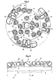
- Fig. 1 shows a top view of a drill bit according to the invention.
- Fig. 2 shows a vertical projection of the drill bit in Fig. 1, the roller cutters have been rotated from their positions in Fig. 1 and superpositioned relative each other in order to illustrate the profile that the drill hole is given.
- Fig. 3 shows a top view of the drill bit in Fig. 2, however only two roller cutters are disclosed, illustrating the circles along which the cutting means of said roller cutters move when the drill bit is rotating.
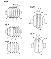
- Fig. 4 shows in detail the superposition in Fig. 2 of the roller cutters and thus the distance between the rows that is achieved during drilling.
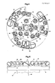
- Figs. 5-8 correspond to Figs. 1-4 with the exception that the distance between the rows is bigger.
- Fig. 9 illustrates the superposition of the roller cutters in a drill bit having the same distance between the rows as the drill bit according to Figs. 5-8 with the exception that there are a smaller number of roller cutters.
- Fig. 10 shows a roller cutter according to the invention.
- Fig. 11 shows the roller cutter of Fig. 10 in a reversed position.
- the drill bit in the drawings generally designated by the reference number 10 comprises a frame 11.
- a number of roller cutters 13-38, in the disclosed embodiment twenty-six, are mounted in brackets or saddles, the saddles 12 for the roller cutters 16-31 being identical to each other.
- the roller cutter 13 is of a type disclosed in DE,B, 3521159 and the roller cutters 14, 15 have a conventional conical design.
- the roller cutters 13-15 are intended to machine the portion of the frontal face 39 that is closest to the rotational axis 40 of the drill bit.
- the roller cutters 16-38 are designed with two rows 41,42 of cutting means, e g hard material inserts, said rows being displaced in the axial direction of the roller cutter.
- the roller cutters 16-38 are cylindrical and their shaft journals 43, 44 are identical. This means that the roller cutters are reversibly mountable in their saddles 12 and that the cutting means of the roller cutters are engaging the frontal face 39 even if the roller cutters are reversed.
- the rows 41, 42 of cutting means are located on each side of the transverse symmetry plane 45 of the roller cutter 16-38.
- the distance B between one row 42 and the symmetry plane 45 is longer than the distance A between a second row 41 and the symmetry plane 45.
- the distance B is essentially three times the distance A.
- the rows of cutting means of the roller cutters 13-38 are arranged to move along concentric circles when the drill bit 10 rotates around the axis 40 of rotation.
- the rows 41', 42' of cutting means of the roller cutter 20 move along a first series of circles 46, 47 and the rows 41", 42" of cutting means of the roller cutter 19 move along a second series of circles 48, 49.
- the saddles 12 of the roller cutters 19, 20 are located at such distance from the axis 40 of rotation that, in the preferred embodiment, the distance B is three times the distance A, the circles 46-49 being located at the same distance from the axis 40 of rotation and in the order 48, 47, 49, 46 from said axis.
- Fig. 4 is disclosed four at radial distance from the centre axis 40 adjacent each other located roller cutters 19-22, said roller cutters being superpositioned, the roller cutters 19 and 21 being mounted in the position of Fig. 11 and the roller cutters 20 and 22 in the position of Fig. 10.
- each of the rows 41, 42 of cutting means on the roller cutters 20, 22 moves along an own circle in the first series of circles when the drill bit is rotating and that each of the rows 41, 42 of cutting means on the roller cutters 19, 21 moves along an own circle in the second series of circles, said distance between two consecutive circles being 2A.
- the saddles for the roller cutters 16-32 are arranged in such a way that the distance between the rows can be varied by these roller cutters, said each row of cutting means on all roller cutters 16-32 move along an own circle in the first and the second resp series of circles.
- the drill bit of Fig. 1 is provided with a first and a second collection internally alike saddles 12, the first collection of saddles carrying the roller cutters, 16, 18, 20, 22, 24, 26, 28, 30 and 32 and the other collection of saddles carrying the roller cutters 17, 19, 21, 23, 25, 27, 29 and 31.
- These saddles are consequently located at such distance from the axis 40 of rotation that the rows 41, 42 of cutting means on the roller cutters 16, 18, 20, 22, 24, 26, 28, 30 and 32 move along the first series of circles when these roller cutters are mounted in the first position, i e in the position of Fig. 10, and the rows 41, 42 of cutting means on the roller cutters 17, 19, 21, 23, 25, 27, 29 and 31 move along the other series of circles when the last-mentioned roller cutters are mounted in the other position, i e the position of Fig. 11.
- Fig. 5 it is disclosed how the roller cutters 16, 18, 20, 22, 24, 26, 28, 30 and 32 have been reversed from the first position of Fig. 10 to the second position of Fig. 11.
- the four adjacent located roller cutters 19-22 being superpositioned, the distance between two consecutive circles are A + B or 4A, the rows 41, 42 of cutting means moving along said circles.
- each of the rows 41, 42 of cutting means of the roller cutters 16, 18, 20, 22, 24, 26, 28, 30 and 32 will move along circles that are included in that series of circles along which the cutting means of the roller cutters 17, 19, 21, 23, 25, 27, 29 and 31 are moving.
- Fig. 7 disclosing for the sake of clearness only the roller cutters 19, 20.
- the distance between rows of the drill bit according to Fig. 5 is thus twice as big as the distance between rows of the drill bit according to Fig. 1, the number of rows of cutting means that are in engagement with the frontal face 39 being unchanged.
- roller cutters 16, 18, 20, 22, 24, 26, 28, 30 and 32 are preferably deleted. This means that only one row 41, 42 of cutting means will move along a given circle.
- the invention can also have application for other types of roller cutters, e g roller cutters having cutting means in the shape of steel discs. Also the invention can be applied in raise boring when a pre-drilled pilote hole is reamed by a drill bit having a large diameter. In such a drill bit no centre roller cutters 13, 14, 15 are needed.
Landscapes
- Engineering & Computer Science (AREA)
- Geology (AREA)
- Mining & Mineral Resources (AREA)
- Life Sciences & Earth Sciences (AREA)
- General Life Sciences & Earth Sciences (AREA)
- Fluid Mechanics (AREA)
- Environmental & Geological Engineering (AREA)
- Physics & Mathematics (AREA)
- Mechanical Engineering (AREA)
- Geochemistry & Mineralogy (AREA)
- Earth Drilling (AREA)
- Drilling Tools (AREA)
- Excavating Of Shafts Or Tunnels (AREA)
- Drilling And Boring (AREA)
- Finish Polishing, Edge Sharpening, And Grinding By Specific Grinding Devices (AREA)
- Numerical Control (AREA)
- Perforating, Stamping-Out Or Severing By Means Other Than Cutting (AREA)
Priority Applications (2)
| Application Number | Priority Date | Filing Date | Title |
|---|---|---|---|
| EP91200364A EP0435861B1 (de) | 1985-10-11 | 1986-09-26 | Rollenschneide für einen Bohrmeisse |
| AT86850326T ATE75524T1 (de) | 1985-10-11 | 1986-09-26 | Bohrmeissel und dazugehoerige schneidrolle. |
Applications Claiming Priority (2)
| Application Number | Priority Date | Filing Date | Title |
|---|---|---|---|
| SE8504711A SE459436B (sv) | 1985-10-11 | 1985-10-11 | Borrhuvud och skaerrulle avsedd att anvaendas vid detta |
| SE8504711 | 1985-10-11 |
Related Child Applications (1)
| Application Number | Title | Priority Date | Filing Date |
|---|---|---|---|
| EP91200364.7 Division-Into | 1986-09-26 |
Publications (3)
| Publication Number | Publication Date |
|---|---|
| EP0218567A2 true EP0218567A2 (de) | 1987-04-15 |
| EP0218567A3 EP0218567A3 (en) | 1988-11-02 |
| EP0218567B1 EP0218567B1 (de) | 1992-04-29 |
Family
ID=20361700
Family Applications (2)
| Application Number | Title | Priority Date | Filing Date |
|---|---|---|---|
| EP91200364A Expired - Lifetime EP0435861B1 (de) | 1985-10-11 | 1986-09-26 | Rollenschneide für einen Bohrmeisse |
| EP86850326A Expired - Lifetime EP0218567B1 (de) | 1985-10-11 | 1986-09-26 | Bohrmeissel und dazugehörige Schneidrolle |
Family Applications Before (1)
| Application Number | Title | Priority Date | Filing Date |
|---|---|---|---|
| EP91200364A Expired - Lifetime EP0435861B1 (de) | 1985-10-11 | 1986-09-26 | Rollenschneide für einen Bohrmeisse |
Country Status (9)
| Country | Link |
|---|---|
| US (1) | US4832136A (de) |
| EP (2) | EP0435861B1 (de) |
| AT (2) | ATE131571T1 (de) |
| AU (1) | AU593019B2 (de) |
| CA (1) | CA1254195A (de) |
| DE (2) | DE3685076D1 (de) |
| NO (1) | NO175913C (de) |
| SE (1) | SE459436B (de) |
| ZA (1) | ZA867512B (de) |
Families Citing this family (6)
| Publication number | Priority date | Publication date | Assignee | Title |
|---|---|---|---|---|
| WO1999018326A1 (en) * | 1997-10-06 | 1999-04-15 | Excavation Engineering Associates, Inc. | Small disc cutters, and drill bits, cutterheads, and tunnel boring machines employing such rolling disc cutters |
| DE10150685B4 (de) * | 2001-10-17 | 2007-06-14 | Wirth Maschinen- und Bohrgeräte-Fabrik GmbH | Arbeitskopf mit veränderbarem Schneidabstand der Schneidrollen für eine Vorrichtung zum Vortreiben von Strecken, Tunneln oder dergleichen |
| US7370711B2 (en) * | 2005-08-15 | 2008-05-13 | Smith International, Inc. | Rolling cone drill bit having non-circumferentially arranged cutter elements |
| US7686104B2 (en) * | 2005-08-15 | 2010-03-30 | Smith International, Inc. | Rolling cone drill bit having cutter elements positioned in a plurality of differing radial positions |
| US9016407B2 (en) * | 2007-12-07 | 2015-04-28 | Smith International, Inc. | Drill bit cutting structure and methods to maximize depth-of-cut for weight on bit applied |
| WO2009146078A1 (en) * | 2008-04-01 | 2009-12-03 | Smith International, Inc. | Fixed cutter bit with backup cutter elements on secondary blades |
Family Cites Families (13)
| Publication number | Priority date | Publication date | Assignee | Title |
|---|---|---|---|---|
| US1646620A (en) * | 1923-09-04 | 1927-10-25 | F M Fishback | Rotary disk drill |
| DE1805336A1 (de) * | 1968-10-25 | 1970-05-14 | Edelstahlwerk J C Soeding & Ha | Bohrgeraet |
| US3756332A (en) * | 1971-11-01 | 1973-09-04 | Robbins Co | Disc type center cutter for a boring machine |
| ZA723776B (en) * | 1972-06-02 | 1974-01-30 | Hard Metals Ltd | Disc cutting unit for use on rock boring machines |
| US3797592A (en) * | 1972-11-21 | 1974-03-19 | Kennametal Inc | Stabilizing roller |
| US3863994A (en) * | 1973-09-24 | 1975-02-04 | Jarva Corp | Bidirectional roller cutter |
| SU754058A1 (ru) * | 1976-06-22 | 1980-08-07 | Московский Ордена Трудового Красного Знамени Горный Институт | Проходческий комбайн дл электротермической проходки горных выработок |
| DE2742019C3 (de) * | 1977-09-17 | 1980-07-03 | Demag Ag, 4100 Duisburg | Rollenbohrwerkzeug für Tunnelvortriebsmaschinen |
| DE2838154C3 (de) * | 1978-09-01 | 1981-09-17 | Mannesmann Demag Ag, 4100 Duisburg | Rotierender mit sternförmig nach außen gerichteten Armen versehener Bohrkopf für Vollschnitt-Tunnelvortriebsmaschinen |
| SE463110B (sv) * | 1979-02-02 | 1990-10-08 | Sandvik Ab | Saett och anordning foer stigortsdrivning |
| US4381038A (en) * | 1980-11-21 | 1983-04-26 | The Robbins Company | Raise bit with cutters stepped in a spiral and flywheel |
| DE3132345C1 (de) * | 1981-08-17 | 1983-01-13 | Wirth Maschinen- und Bohrgeräte-Fabrik GmbH, 5140 Erkelenz | Halterung fuer Schneidwerkzeuge auf Bohrkoepfen |
| SE457656B (sv) * | 1984-06-18 | 1989-01-16 | Santrade Ltd | Borrkrona innefattande en roterande skaerrulle och borrhuvud innefattande saadan borrkrona |
-
1985
- 1985-10-11 SE SE8504711A patent/SE459436B/sv not_active IP Right Cessation
-
1986
- 1986-09-26 EP EP91200364A patent/EP0435861B1/de not_active Expired - Lifetime
- 1986-09-26 DE DE8686850326T patent/DE3685076D1/de not_active Expired - Lifetime
- 1986-09-26 DE DE3650450T patent/DE3650450T2/de not_active Expired - Fee Related
- 1986-09-26 EP EP86850326A patent/EP0218567B1/de not_active Expired - Lifetime
- 1986-09-26 AT AT91200364T patent/ATE131571T1/de not_active IP Right Cessation
- 1986-09-26 AT AT86850326T patent/ATE75524T1/de not_active IP Right Cessation
- 1986-09-30 AU AU63254/86A patent/AU593019B2/en not_active Ceased
- 1986-10-01 ZA ZA867512A patent/ZA867512B/xx unknown
- 1986-10-10 CA CA000520253A patent/CA1254195A/en not_active Expired
- 1986-10-10 NO NO864047A patent/NO175913C/no not_active IP Right Cessation
-
1988
- 1988-02-16 US US07/158,097 patent/US4832136A/en not_active Ceased
Also Published As
| Publication number | Publication date |
|---|---|
| NO175913C (no) | 1994-12-28 |
| EP0435861A3 (en) | 1992-04-29 |
| EP0218567B1 (de) | 1992-04-29 |
| AU593019B2 (en) | 1990-02-01 |
| SE8504711L (sv) | 1987-04-12 |
| DE3650450T2 (de) | 1996-05-02 |
| EP0435861B1 (de) | 1995-12-13 |
| US4832136A (en) | 1989-05-23 |
| SE459436B (sv) | 1989-07-03 |
| SE8504711D0 (sv) | 1985-10-11 |
| NO864047L (no) | 1987-04-13 |
| EP0435861A2 (de) | 1991-07-03 |
| DE3685076D1 (de) | 1992-06-04 |
| NO864047D0 (no) | 1986-10-10 |
| ATE131571T1 (de) | 1995-12-15 |
| ZA867512B (en) | 1987-05-27 |
| CA1254195A (en) | 1989-05-16 |
| NO175913B (no) | 1994-09-19 |
| DE3650450D1 (de) | 1996-01-25 |
| ATE75524T1 (de) | 1992-05-15 |
| AU6325486A (en) | 1987-04-16 |
| EP0218567A3 (en) | 1988-11-02 |
Similar Documents
| Publication | Publication Date | Title |
|---|---|---|
| US4936398A (en) | Rotary drilling device | |
| US4187922A (en) | Varied pitch rotary rock bit | |
| US4334586A (en) | Inserts for drilling bits | |
| US5090492A (en) | Drill bit with vibration stabilizers | |
| US5282512A (en) | Drilling tool with rotating conical rollers | |
| US4641718A (en) | Rotary drill bit | |
| US4274496A (en) | Method and device in earth cutting | |
| US5429201A (en) | Drill bit with improved rolling cutter tooth pattern | |
| CA2305742A1 (en) | Small disc cutters, and drill bits, cutterheads, and tunnel boring machines employing such rolling disc cutters | |
| US4316515A (en) | Shaft drill bit with improved cutter bearing and seal arrangement and cutter insert arrangement | |
| US5456328A (en) | Drill bit with improved rolling cutter tooth pattern | |
| US4420050A (en) | Oil well drilling bit | |
| EP0435861B1 (de) | Rollenschneide für einen Bohrmeisse | |
| US4202419A (en) | Roller cutter with major and minor insert rows | |
| USRE34167E (en) | Drill bit and roller cutter for said drill bit | |
| US4441566A (en) | Drill bit with dispersed cutter inserts | |
| CA1110226A (en) | Shaft drill bit with overlapping cutter arrangement | |
| US4393949A (en) | Rock boring apparatus | |
| US20040020693A1 (en) | Drill bit | |
| US4231438A (en) | Straight hole insert drill bit | |
| AU2002212221A1 (en) | Drill bit | |
| CA1053657A (en) | Earth boring auger | |
| AU727657B2 (en) | Drill bit | |
| US1867531A (en) | Deep well drilling apparatus | |
| US2047116A (en) | Rotary earth boring drill |
Legal Events
| Date | Code | Title | Description |
|---|---|---|---|
| PUAI | Public reference made under article 153(3) epc to a published international application that has entered the european phase |
Free format text: ORIGINAL CODE: 0009012 |
|
| AK | Designated contracting states |
Kind code of ref document: A2 Designated state(s): AT CH DE FR IT LI SE |
|
| PUAL | Search report despatched |
Free format text: ORIGINAL CODE: 0009013 |
|
| RHK1 | Main classification (correction) |
Ipc: E21B 10/10 |
|
| AK | Designated contracting states |
Kind code of ref document: A3 Designated state(s): AT CH DE FR IT LI SE |
|
| 17P | Request for examination filed |
Effective date: 19881119 |
|
| 17Q | First examination report despatched |
Effective date: 19890818 |
|
| GRAA | (expected) grant |
Free format text: ORIGINAL CODE: 0009210 |
|
| ITF | It: translation for a ep patent filed | ||
| AK | Designated contracting states |
Kind code of ref document: B1 Designated state(s): AT CH DE FR IT LI SE |
|
| REF | Corresponds to: |
Ref document number: 75524 Country of ref document: AT Date of ref document: 19920515 Kind code of ref document: T |
|
| XX | Miscellaneous (additional remarks) |
Free format text: TEILANMELDUNG 91200364.7 EINGEREICHT AM 26/09/86. |
|
| REF | Corresponds to: |
Ref document number: 3685076 Country of ref document: DE Date of ref document: 19920604 |
|
| ET | Fr: translation filed | ||
| PLBE | No opposition filed within time limit |
Free format text: ORIGINAL CODE: 0009261 |
|
| STAA | Information on the status of an ep patent application or granted ep patent |
Free format text: STATUS: NO OPPOSITION FILED WITHIN TIME LIMIT |
|
| 26N | No opposition filed | ||
| EAL | Se: european patent in force in sweden |
Ref document number: 86850326.9 |
|
| PGFP | Annual fee paid to national office [announced via postgrant information from national office to epo] |
Ref country code: SE Payment date: 20030904 Year of fee payment: 18 |
|
| PGFP | Annual fee paid to national office [announced via postgrant information from national office to epo] |
Ref country code: FR Payment date: 20030909 Year of fee payment: 18 |
|
| PGFP | Annual fee paid to national office [announced via postgrant information from national office to epo] |
Ref country code: AT Payment date: 20030911 Year of fee payment: 18 |
|
| PGFP | Annual fee paid to national office [announced via postgrant information from national office to epo] |
Ref country code: CH Payment date: 20030930 Year of fee payment: 18 |
|
| PGFP | Annual fee paid to national office [announced via postgrant information from national office to epo] |
Ref country code: DE Payment date: 20031009 Year of fee payment: 18 |
|
| PG25 | Lapsed in a contracting state [announced via postgrant information from national office to epo] |
Ref country code: AT Free format text: LAPSE BECAUSE OF NON-PAYMENT OF DUE FEES Effective date: 20040926 |
|
| PG25 | Lapsed in a contracting state [announced via postgrant information from national office to epo] |
Ref country code: SE Free format text: LAPSE BECAUSE OF NON-PAYMENT OF DUE FEES Effective date: 20040927 |
|
| PG25 | Lapsed in a contracting state [announced via postgrant information from national office to epo] |
Ref country code: LI Free format text: LAPSE BECAUSE OF NON-PAYMENT OF DUE FEES Effective date: 20040930 Ref country code: CH Free format text: LAPSE BECAUSE OF NON-PAYMENT OF DUE FEES Effective date: 20040930 |
|
| PG25 | Lapsed in a contracting state [announced via postgrant information from national office to epo] |
Ref country code: DE Free format text: LAPSE BECAUSE OF NON-PAYMENT OF DUE FEES Effective date: 20050401 |
|
| EUG | Se: european patent has lapsed | ||
| REG | Reference to a national code |
Ref country code: CH Ref legal event code: PL |
|
| PG25 | Lapsed in a contracting state [announced via postgrant information from national office to epo] |
Ref country code: FR Free format text: LAPSE BECAUSE OF NON-PAYMENT OF DUE FEES Effective date: 20050531 |
|
| REG | Reference to a national code |
Ref country code: FR Ref legal event code: ST |
|
| PG25 | Lapsed in a contracting state [announced via postgrant information from national office to epo] |
Ref country code: IT Free format text: LAPSE BECAUSE OF NON-PAYMENT OF DUE FEES;WARNING: LAPSES OF ITALIAN PATENTS WITH EFFECTIVE DATE BEFORE 2007 MAY HAVE OCCURRED AT ANY TIME BEFORE 2007. THE CORRECT EFFECTIVE DATE MAY BE DIFFERENT FROM THE ONE RECORDED. Effective date: 20050926 |