EP0218653B1 - Vorrichtung zum prüfen des rohrleitungsinneren - Google Patents
Vorrichtung zum prüfen des rohrleitungsinneren Download PDFInfo
- Publication number
- EP0218653B1 EP0218653B1 EP86902347A EP86902347A EP0218653B1 EP 0218653 B1 EP0218653 B1 EP 0218653B1 EP 86902347 A EP86902347 A EP 86902347A EP 86902347 A EP86902347 A EP 86902347A EP 0218653 B1 EP0218653 B1 EP 0218653B1
- Authority
- EP
- European Patent Office
- Prior art keywords
- pipeline
- carrier
- electro
- optical signal
- signals
- Prior art date
- Legal status (The legal status is an assumption and is not a legal conclusion. Google has not performed a legal analysis and makes no representation as to the accuracy of the status listed.)
- Expired
Links
Images
Classifications
-
- G—PHYSICS
- G01—MEASURING; TESTING
- G01N—INVESTIGATING OR ANALYSING MATERIALS BY DETERMINING THEIR CHEMICAL OR PHYSICAL PROPERTIES
- G01N29/00—Investigating or analysing materials by the use of ultrasonic, sonic or infrasonic waves; Visualisation of the interior of objects by transmitting ultrasonic or sonic waves through the object
- G01N29/22—Details, e.g. general constructional or apparatus details
- G01N29/26—Arrangements for orientation or scanning by relative movement of the head and the sensor
- G01N29/265—Arrangements for orientation or scanning by relative movement of the head and the sensor by moving the sensor relative to a stationary material
-
- G—PHYSICS
- G01—MEASURING; TESTING
- G01M—TESTING STATIC OR DYNAMIC BALANCE OF MACHINES OR STRUCTURES; TESTING OF STRUCTURES OR APPARATUS, NOT OTHERWISE PROVIDED FOR
- G01M3/00—Investigating fluid-tightness of structures
- G01M3/005—Investigating fluid-tightness of structures using pigs or moles
Definitions
- This invention relates to the internal inspection of pipelines for carrying fluids, such as oil or gas, over considerable distance, subsea or overland, between accessible ends of individual pipeline sections.
- Pipelines of this kind which are normally inaccessible from the outside must be inspected at regular intervals from the inside for possible corrosion attacks, cracking, or other defects, in order to prevent costly production interruptions, catastrophic failures, and/or disasterous sever- ances of the supply of energy to the community.
- apparatus carriers For such internal inspections, a great variety of apparatus carriers, pressure-driven pigs - of self-propelled « crawlers •, have been developed and used for carrying visual, magnetic, electric, ultrasonic or similar non-destructive examination apparatus through a pipeline from a launching trap at one end to a receiving trap at the other end of a pipeline section.
- apparatus carriers may contain pressure-tight capsules for non-destructive examination apparatus, position determining apparatus, recording means, driving mechanisms, and battery or turbo-generator units for energizing the various apparatus in the carrier.
- the recording means After the passage of the apparatus carrier, the recording means may then be removed and connected to display and recording means situated. outside the pipeline for analysis, evaluation, and permanent recording of the results of the inspection.
- An extensive description of an inspection system of this kind has been given in U.S. Scherbatskoy Patent No. 2,940,302.
- the system according to the present invention has been evolved with the general object of overcoming the disadvantages of prior systems and providing a system for the internal inspection of a pipeline in which it has become possible to obtain continuous on-line communication over considerable distances between a control station situated outside the pipeline and an apparatus carrier during the progression of the carrier through an entire pipeline section to be examined.
- this communication possibility is obtained through the use of one or more expendable, thin optical fibres connected and adapted to transmit optical measurement and control signals between the carrier and an outside control station.
- One or more coils of optical fibres having at least the same length as the pipeline section are mounted on the apparatus carrier, and the fibres are gradually deposited inside the pipeline during the progression of the carrier.
- the optical fibres Upon completion of the inspection, the optical fibres are discarded inside the pipeline or, if it should be considered necessary, removed by a subsequent routine in-service cleaning operation.
- the optical fibres are connected at both ends to conventional electro-optical signal converters mounted in the apparatus carrier and in the outside control station, respectively, and adapted to convert electronic measurement and control signals into corresponding optical signals, and to convert such optical signals back into equivalent electronic signals.
- Electro-optical signal converters of this kind may, in principle, be installed and connected in any inspection apparatus carrier known in the state of the art, and in any known corresponding display, recording or control means situated outside the carrier launching end of the pipeline section to be examined.
- One important object of the invention is to make it possible to transmit measurement signals from the non-destructive examination apparatus and from the position determining apparatus mounted in the apparatus carrier to an outside control station for producing instant on-line visual displays of the step-by-step conditions of the pipeline wall material and surfaces, and permanent recordings of the results of the inspection.
- Another important object of the invention is to make it possible to transmit control signals from outside control means to the apparatus carrier for obtaining step-by-step on-line control of the functions of the non-destructive examination apparatus installed in the apparatus carrier.
- control may comprise on/off switching of the various apparatus, directing and focusing of television cameras and corresponding illuminating systems, changing between different examination probes and scanning patterns, and several similar controlling operations as required.
- Still another important object of the invention is to make it possible to transmit control signals from outside control means to a self-propelled apparatus carrier for obtaining step-by-step on-line control of the functions of the driving mechanisms of the apparatus carrier.
- control may comprise on/off switching, control of battery or turbo-generator energizing systems, control of direction and rate of progress of the carrier for closer inspection of suspicious-looking areas of the pipeline wall, and similar control operations as required.
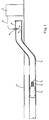
- Figure 1 shows schematically part of a section of a pipeline 1 for carrying fluids, such as oil or gas.
- the main part of the pipeline is buried below the earth's surface 2 and is thus normally inaccessible from the outside.
- An apparatus carrier 3 is inserted in one end 6 of the section of pipeline 1.
- the apparatus carrier 3 is adapted to travel inside the pipeline from point to point until it reaches the other end of the pipeline section.
- a coil 4 of expendable, thin optical fibre 5, having at least the same length as the section of the pipeline to be inspected is mounted on the apparatus carrier 3.
- the coil 4 is adapted to gradually deposit the optical fibre 5 during the progression of the carrier 3 through the pipeline 1.
- the optical fibre 5 connects the apparatus carrier 3 with an outside control station 7 situated at the carrier launching end 6 of the pipeline 1.
- a bushing 8 is fitted into the wall of the pipeline at the carrier launching end 6 and adapted to receive a pressure-tight lead-in plug 9 for the optical fibre 5.
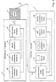
- FIG. 2 shows schematically in more detail the components of the apparatus carrier 3 and the control station 7.
- the apparatus carrier 3 contains non-destructive examination apparatus 10 ' adapted to generate electronic measurement signals representative of the successive conditions of the pipeline wall material and surfaces.
- the apparatus carrier 3 further contains position determining apparatus 11 adapted to generate electronic position signals representative of the successive positions of the carrier during its course of travel.
- the electronic measurement and position signals are transmitted to a first electro-optical signal converter 12 installed in the apparatus carrier 3 and adapted to convert the electronic signals into corresponding optical signals which are then transmitted through the optical fibre 5 to a second electro-optical signal converter 13 installed in the outside control station 7 and adapted to convert said optical signals back into equivalent electronic measurement and position signals.
- These latter electronic signals are then transmitted to display means 14 for generating visual displays of the results of the examinations, and to recording means 15 for producing permanent records of the results of the inspection of the pipeline.
- the control station 7 further contains first control means 16 adapted to generate electronic control signals for controlling the functions of the non-destructive examination apparatus 10, and adapted to transmit the control signals to the second electro-optical signal converter 13.
- the signal converter 13 is further adapted to convert said electronic control signals into corresponding optical signals which are then transmitted through the optical fibre 5 to the first electro-optical signal converter 12 installed in the apparatus carrier 3 and further adapted to convert said optical signals back into equivalent electronic control signals. These latter electronic control signals are then transmitted to the non-destructive examination apparatus 10 which is adapted to have its functions controlled by said electronic control signals.
- the apparatus carrier 3 of the embodiment shown is further adapted to be self-propelled by means of a driving mechanism 17.
- Second control means 18 installed in the outside control station 7 are adapted to generate electronic control signals for controlling the function of the driving mechanism 17, and to transmit the control signals to the second electro-optical signal converter 13.
- the second signal converter 13 is further adapted to convert said electronic control signals into corresponding optical signals which are then transmitted through the optical fibre 5 to the first electro-optical signal converter 12 installed in the apparatus carrier 3 which is further adapted to convert said optical control signals back into equivalent electronic control signals.
- These latter electronic control signals are then transmitted to the driving mechanism 17 to have its functions controlled by said electronic control signals.
- the apparatus carrier 3 may, in principle, be of any kind among the great variety of such carriers, pressure-driven or self-propelled, which are known and used in the art. Provided, of course, that the carrier 3 is constructed to enable installing the first electro-optical signal converter 12 and to mount the optical fibre coil 4. Typically, such apparatus carriers may consist of a number of pressure-tight capsules containing the different kinds of apparatus and mechanisms to be carried through the pipeline.
- the coil 4 of optical fibre 5 may be an open coil, from the inside or outside of which the fibre is freely and gradually unrolled or uncoiled and deposited inside the pipeline during progressive movement of the apparatus carrier 3 through the pipeline. Also, the coil may be supplemented by any readily apparent dispensing means fulfilling the same purpose. In some instances it may be considered practical to use two or more coils 4 of optical fibres 5 working in parallel, each for its own signal transmission purposes.
- the optical fibre 5 may be of any kind known and used in the art for the transmission of optical signals, provided that the optical fibre can be considered expendable in the great lengths normally required and that the fibres can be discarded inside the pipeline or readily removed after the inspecticn process is completed by a routine cleaning operation without any harmful effects to the normal functioning of the pipeline system. Given these conditions, the fibres may be designed or coated to have sufficient strength and corrosion resistance etc. to function inside the pipeline under the duration of the inspection procedure. In the case of very long pipeline sections it may be necessary to insert one or more miniaturized, battery driven signal regenerators between continuous lengths of optical fibre in order to ensure safe long-distance transmission of the optical signals.
- the bushing 8 for receiving the lead-in plug 9 makes it possible to perform the inspection without interruption of the transportation of fluid through the pipeline, provided that the bushing 8 is fitted into the launching trap normally used under these circumstances for the insertion of inspection apparatus carriers and cleaning brushes to be passed through the pipeline.
- the bushing 8 and the lead-in plug 9 may be designed in several ways readily apparent to those skillec in the art of designing high-pressure components.
- the optical fibre may be embedded in a prefabricated glass bar forming the plug 9 fitting into bushing 8.
- the non-destructive examination apparatus 10 may be of any kind known and used in the art, provided that the apparatus is able to sense characteristic properties representative of the safety conditions of the pipeline wall material or surfaces, and provided that the apparatus is able to generate corresponding electronic measurement signals representative of these properties.
- Typical examples of non-destructive examination methods that have been used or may be used for this purpose are remote television with artificial illumination, pressure or vacuum leak testing, ultrasonic examination in all known forms, magnetic flux leakage measurements, and electric measurements such as eddy current examination or corrosion potential measurements.
- Further examples, some of which may be used in conjunction with television and artificial illumination are magnetographic and magnetic particle or capillary penetrant examinations, hardness testing and chemical surface analyses.
- the position determining apparatus 11 may be of any kind known and used in the state of the art, provided that the step by step position of the apparatus carrier 3 is transformed into corresponding electronic position signals.
- Typical examples of the position determining principles that have been used for this purpose are the counting of circumferential welds or magnetic markers embedded in the pipeline insulation at known intervals, or revolution counting in connection with the driving mechanisms of self-propelled apparatus carriers.
- the non-destructive examination apparatus 10 and the position determining apparatus 11 may be energized by electric batteries installed in the apparatus carrier or, in the case of in-service inspections, by a turbo-generator mechanism activated by the motion of the fluid in the pipeline as described in the above-mentioned U.S. Scherbatskoy Patent No. 2,940,302.
- the driving mechanism 17 may be of any kind known and used for this purpose in the art, provided that the functions of the driving mechanism can be controlled by appropriate electronic control signals.
- the driving mechanism may be energized by electric batteries installed in the apparatus carrier 3 or by a turbo-generator mechanism activated by the motion of the fluid in the pipeline. The motion of the apparatus carrier may then be brought about by wheels or caterpillar treads in contact with the internal surface of the pipeline.
- the first and second electro-optical signal converters 12 and 13 may be of any kind known and used in the art of fibre-optical signal transmission. Single converters may be used, provided that they are able to convert electronic measurement signals into optical signals as well as optical control signals into electronic signals. If it is considered practical to use two or more optical fibres 5 working in parallel, a corresponding number of electro-optical signal converters 12 and 13 will be installed in the apparatus carrier 3 and in the outside control station 7, respectively.
- the display means 14 may be of any kind known and used in the art in conjunction with the types of non-destructive examination apparatus 10 and position determining apparatus 11 employed, provided that display means 14 is able to generate on-line displays in the form of monitor screen images representative of the step-by-step measurements performed. Typical examples of such display means, able to generate complete projection images of the results of ultrasonic examinations on a television monitor screen, have been described in U.S. Lund et al. Patent Nos. 3,939,697 and 4,226,122.
- the recording means 15 may similarly be of any kind known and used in the art in conjunction with the particular non-destructive examination and position determining apparatus 10 and 11, respectively, employed, provided that recording means 15 is able to produce permanent records of the step-by-step measurements performed, preferably in such a manner that it becomes possible at any later time to recreate monitor screen images of the results of the examinations.
- a great variety of computerized non-destructive examination systems utilizing permanent storage of measurement data on magnetic tapes or disks will satisfy these provisions.
- a typical example of such recording means is the computerized ultrasonic examination system described in the above-mentioned U.S. Lund et al. Patent No. 4,226,122.
- non-destructive examination apparatus control means 16 and driving mechanism control means 18 may similarly be of any kind known and used in the art, provided that they are able to generate the appropriate electronic control signals for controlling the functions of the particular apparatus 10 and mechanism 17 employed.
- the display, recording and control means 14, 15, 16 and 18 of the outside control station 7 can be combined into one integrated, computerized and keyboard controlled electronic data processing system.
Landscapes
- Physics & Mathematics (AREA)
- General Physics & Mathematics (AREA)
- General Health & Medical Sciences (AREA)
- Chemical & Material Sciences (AREA)
- Analytical Chemistry (AREA)
- Biochemistry (AREA)
- Life Sciences & Earth Sciences (AREA)
- Health & Medical Sciences (AREA)
- Immunology (AREA)
- Pathology (AREA)
- Investigating Materials By The Use Of Optical Means Adapted For Particular Applications (AREA)
- Investigating Or Analyzing Materials By The Use Of Magnetic Means (AREA)
- Rigid Pipes And Flexible Pipes (AREA)
- Supports For Pipes And Cables (AREA)
Claims (9)
Applications Claiming Priority (2)
| Application Number | Priority Date | Filing Date | Title |
|---|---|---|---|
| US721678 | 1985-04-10 | ||
| US06/721,678 US4679448A (en) | 1985-04-10 | 1985-04-10 | System for the internal inspection of pipelines |
Publications (2)
| Publication Number | Publication Date |
|---|---|
| EP0218653A1 EP0218653A1 (de) | 1987-04-22 |
| EP0218653B1 true EP0218653B1 (de) | 1989-03-15 |
Family
ID=24898872
Family Applications (1)
| Application Number | Title | Priority Date | Filing Date |
|---|---|---|---|
| EP86902347A Expired EP0218653B1 (de) | 1985-04-10 | 1986-04-08 | Vorrichtung zum prüfen des rohrleitungsinneren |
Country Status (6)
| Country | Link |
|---|---|
| US (1) | US4679448A (de) |
| EP (1) | EP0218653B1 (de) |
| DE (1) | DE3662467D1 (de) |
| DK (1) | DK576386D0 (de) |
| NO (1) | NO864920L (de) |
| WO (1) | WO1986006165A1 (de) |
Families Citing this family (15)
| Publication number | Priority date | Publication date | Assignee | Title |
|---|---|---|---|---|
| US4945758A (en) * | 1987-05-28 | 1990-08-07 | Arabian American Oil Company | Method and apparatus for monitoring the interior surface of a pipeline |
| GB2242497B (en) * | 1990-03-31 | 1992-08-12 | Stc Plc | Pipe inspection system |
| US5174165A (en) * | 1990-08-13 | 1992-12-29 | Westinghouse Electric Corp. | Flexible delivery system for a rotatable probe |
| AT405335B (de) * | 1993-12-30 | 1999-07-26 | Oemv Ag | Vorrichtung und verfahren zur bestimmung von fehlstellen einer rohrleitung für fluide |
| NL1011525C2 (nl) * | 1999-03-11 | 2000-09-12 | A Hak Ind Services B V | Inrichting voor het inwendig inspecteren van pijpen en buizen of dergelijke. |
| DK1531959T3 (da) * | 2002-07-17 | 2008-06-16 | Shell Int Research | Fremgangsmåde ti sammenföjning af udvidelige rör |
| CN100406187C (zh) * | 2002-07-25 | 2008-07-30 | 国际壳牌研究有限公司 | 管的锻焊 |
| US7282663B2 (en) | 2002-07-29 | 2007-10-16 | Shell Oil Company | Forge welding process |
| US7774917B2 (en) * | 2003-07-17 | 2010-08-17 | Tubefuse Applications B.V. | Forge welding tubulars |
| FR2868148B1 (fr) * | 2004-03-26 | 2006-06-02 | Enertag Soc Par Actions Simpli | Procede et dispositif pour la localisation d'anomalies situees a l'interieur d'une structure creuse immergee |
| DE102006048490A1 (de) * | 2006-07-10 | 2008-04-24 | Walter Werne | Verfahren und Vorrichtung zur Überwachung von Bauteilen |
| NO328831B1 (no) | 2007-03-14 | 2010-05-25 | Fras Technology As | System for partikkeltelling |
| DE102011106386A1 (de) | 2011-07-04 | 2013-01-10 | Karl Storz Gmbh & Co. Kg | Endoskopische Anordnung |
| CN105163646B (zh) * | 2013-04-19 | 2017-05-17 | 奥林巴斯株式会社 | 内窥镜 |
| US11066906B2 (en) * | 2017-10-26 | 2021-07-20 | Halliburton Energy Services, Inc. | Submersible vehicle with optical fiber |
Family Cites Families (11)
| Publication number | Priority date | Publication date | Assignee | Title |
|---|---|---|---|---|
| CA670410A (en) * | 1963-09-10 | Jet Line Products | Method and apparatus for introducing lines through conduits | |
| US2940302A (en) * | 1956-04-19 | 1960-06-14 | Serge A Scherbatskoy | Pipe-line exploration |
| US3718978A (en) * | 1970-10-16 | 1973-03-06 | Koevering B Van | Pipeline survey vehicle |
| GB1516307A (en) * | 1974-09-09 | 1978-07-05 | Babcock & Wilcox Ltd | Apparatus for conveying a device for inspecting or performing operations on the interior of a tube |
| JPS56135820A (en) * | 1980-03-27 | 1981-10-23 | Sumitomo Electric Ind Ltd | Observing device for pipeline |
| JPS57198419A (en) * | 1981-05-30 | 1982-12-06 | Sharp Corp | Plug jack type wire built-in optical fiber connector |
| JPS5826256A (ja) * | 1981-08-07 | 1983-02-16 | Kubota Ltd | 管の検査装置 |
| JPS58141135A (ja) * | 1981-10-20 | 1983-08-22 | 富士写真フイルム株式会社 | 固体イメ−ジセンサを用いた内視鏡の画像伝送方式 |
| JPS58137806A (ja) * | 1982-02-10 | 1983-08-16 | Fujikura Ltd | 光ケ−ブル入りパイプの製造方法 |
| US4586079A (en) * | 1983-10-07 | 1986-04-29 | Westinghouse Electric Corp. | Fiberscope delivery system |
| US4572228A (en) * | 1984-12-24 | 1986-02-25 | Cherne Industries, Inc. | Connector valve assembly for inflatable packer device |
-
1985
- 1985-04-10 US US06/721,678 patent/US4679448A/en not_active Expired - Fee Related
-
1986
- 1986-04-08 EP EP86902347A patent/EP0218653B1/de not_active Expired
- 1986-04-08 WO PCT/DK1986/000031 patent/WO1986006165A1/en not_active Ceased
- 1986-04-08 DE DE8686902347T patent/DE3662467D1/de not_active Expired
- 1986-12-01 DK DK576386A patent/DK576386D0/da not_active Application Discontinuation
- 1986-12-08 NO NO864920A patent/NO864920L/no unknown
Also Published As
| Publication number | Publication date |
|---|---|
| WO1986006165A1 (en) | 1986-10-23 |
| DE3662467D1 (en) | 1989-04-20 |
| DK576386A (da) | 1986-12-01 |
| NO864920L (no) | 1986-12-08 |
| US4679448A (en) | 1987-07-14 |
| DK576386D0 (da) | 1986-12-01 |
| EP0218653A1 (de) | 1987-04-22 |
Similar Documents
| Publication | Publication Date | Title |
|---|---|---|
| US4679448A (en) | System for the internal inspection of pipelines | |
| US6935425B2 (en) | Method for utilizing microflowable devices for pipeline inspections | |
| US5408883A (en) | Remotely operated diagnostic tube sampling device and method of sampling | |
| CN102171559B (zh) | 评估管道壁强度损伤的装置和方法 | |
| US4560931A (en) | Self-propelled mobile pipeline inspection apparatus and method for inspecting pipelines | |
| EP0399583B1 (de) | Apparatur und Verfahren zur Analyse der Pulsausbreitung für Prüfung einer Pipeline oder ähnlichem | |
| US7402999B2 (en) | Pulsed eddy current pipeline inspection system and method | |
| US5675251A (en) | Device and method for inspection of pipelines | |
| Makar et al. | Inspecting systems for leaks, pits, and corrosion | |
| EA002668B1 (ru) | Способ и устройство для определения неравномерности толщины стенок недоступных трубопроводов | |
| CN121141841A (zh) | 一种满水排水管道结构性缺陷的探测装置及探测方法 | |
| Dingus et al. | Nondestructive, noninvasive assessment of underground pipelines | |
| EP0075997A2 (de) | Bohrungsvorrichtung | |
| Loskutov et al. | The magnetic method for in-tube nondestructive testing of gas and oil pipelines: The past and the present. | |
| Robinson | Identification and sizing of defects in metallic pipes by remote field eddy current inspection | |
| Eiswirth et al. | Pipe defect characterisation by multi-sensor systems | |
| JPS5932864A (ja) | 管内面の検査装置 | |
| Porter | Use of magnetic flux leakage (MFL) for the inspection of pipelines and storage tanks | |
| Kim et al. | Large‐Diameter Pipes: Condition Inspection and Monitoring Test Bed Implementation in Korea. | |
| Todorov et al. | Assessing the Feasibility of Robotic Systems for Measuring Internal Corrosion Using SWOT Analysis | |
| Camerini et al. | Pipeline Inspection | |
| Staples | A new tool for condition evaluation of cast and ductile iron pipe | |
| Light et al. | Monitoring technology for early detection of internal corrosion for pipeline integrity | |
| Sinha | Pipeline corrosion: its remote detection and corrosion management | |
| Buck et al. | Utilization of Vertiline Wire Conveyed Smart Tools in Gas Storage Field Pipeline Applications |
Legal Events
| Date | Code | Title | Description |
|---|---|---|---|
| PUAI | Public reference made under article 153(3) epc to a published international application that has entered the european phase |
Free format text: ORIGINAL CODE: 0009012 |
|
| 17P | Request for examination filed |
Effective date: 19861211 |
|
| AK | Designated contracting states |
Kind code of ref document: A1 Designated state(s): AT BE CH DE FR GB IT LI LU NL SE |
|
| 17Q | First examination report despatched |
Effective date: 19880506 |
|
| RBV | Designated contracting states (corrected) |
Designated state(s): DE FR GB NL |
|
| GRAA | (expected) grant |
Free format text: ORIGINAL CODE: 0009210 |
|
| AK | Designated contracting states |
Kind code of ref document: B1 Designated state(s): DE FR GB NL |
|
| REF | Corresponds to: |
Ref document number: 3662467 Country of ref document: DE Date of ref document: 19890420 |
|
| ET | Fr: translation filed | ||
| PLBE | No opposition filed within time limit |
Free format text: ORIGINAL CODE: 0009261 |
|
| STAA | Information on the status of an ep patent application or granted ep patent |
Free format text: STATUS: NO OPPOSITION FILED WITHIN TIME LIMIT |
|
| 26N | No opposition filed | ||
| PGFP | Annual fee paid to national office [announced via postgrant information from national office to epo] |
Ref country code: GB Payment date: 19920402 Year of fee payment: 7 |
|
| PGFP | Annual fee paid to national office [announced via postgrant information from national office to epo] |
Ref country code: DE Payment date: 19920403 Year of fee payment: 7 |
|
| PGFP | Annual fee paid to national office [announced via postgrant information from national office to epo] |
Ref country code: FR Payment date: 19920421 Year of fee payment: 7 |
|
| PGFP | Annual fee paid to national office [announced via postgrant information from national office to epo] |
Ref country code: NL Payment date: 19920430 Year of fee payment: 7 |
|
| PG25 | Lapsed in a contracting state [announced via postgrant information from national office to epo] |
Ref country code: GB Effective date: 19930408 |
|
| PG25 | Lapsed in a contracting state [announced via postgrant information from national office to epo] |
Ref country code: NL Effective date: 19931101 |
|
| GBPC | Gb: european patent ceased through non-payment of renewal fee |
Effective date: 19930408 |
|
| NLV4 | Nl: lapsed or anulled due to non-payment of the annual fee | ||
| PG25 | Lapsed in a contracting state [announced via postgrant information from national office to epo] |
Ref country code: FR Effective date: 19931229 |
|
| PG25 | Lapsed in a contracting state [announced via postgrant information from national office to epo] |
Ref country code: DE Effective date: 19940101 |
|
| REG | Reference to a national code |
Ref country code: FR Ref legal event code: ST |