EP0218654B1 - Mehrfachschloss - Google Patents
Mehrfachschloss Download PDFInfo
- Publication number
- EP0218654B1 EP0218654B1 EP19860902349 EP86902349A EP0218654B1 EP 0218654 B1 EP0218654 B1 EP 0218654B1 EP 19860902349 EP19860902349 EP 19860902349 EP 86902349 A EP86902349 A EP 86902349A EP 0218654 B1 EP0218654 B1 EP 0218654B1
- Authority
- EP
- European Patent Office
- Prior art keywords
- rotary part
- draw bar
- main driver
- lock
- driver
- Prior art date
- Legal status (The legal status is an assumption and is not a legal conclusion. Google has not performed a legal analysis and makes no representation as to the accuracy of the status listed.)
- Expired
Links
- 230000007935 neutral effect Effects 0.000 claims abstract description 15
- 230000033001 locomotion Effects 0.000 description 15
- 230000000694 effects Effects 0.000 description 1
- 238000003780 insertion Methods 0.000 description 1
- 230000037431 insertion Effects 0.000 description 1
- 230000003993 interaction Effects 0.000 description 1
- 230000002093 peripheral effect Effects 0.000 description 1
Images


Classifications
-
- E—FIXED CONSTRUCTIONS
- E05—LOCKS; KEYS; WINDOW OR DOOR FITTINGS; SAFES
- E05C—BOLTS OR FASTENING DEVICES FOR WINGS, SPECIALLY FOR DOORS OR WINDOWS
- E05C9/00—Arrangements of simultaneously actuated bolts or other securing devices at well-separated positions on the same wing
- E05C9/02—Arrangements of simultaneously actuated bolts or other securing devices at well-separated positions on the same wing with one sliding bar for fastening when moved in one direction and unfastening when moved in opposite direction; with two sliding bars moved in the same direction when fastening or unfastening
- E05C9/021—Arrangements of simultaneously actuated bolts or other securing devices at well-separated positions on the same wing with one sliding bar for fastening when moved in one direction and unfastening when moved in opposite direction; with two sliding bars moved in the same direction when fastening or unfastening with rack and pinion mechanism
-
- E—FIXED CONSTRUCTIONS
- E05—LOCKS; KEYS; WINDOW OR DOOR FITTINGS; SAFES
- E05C—BOLTS OR FASTENING DEVICES FOR WINGS, SPECIALLY FOR DOORS OR WINDOWS
- E05C9/00—Arrangements of simultaneously actuated bolts or other securing devices at well-separated positions on the same wing
- E05C9/02—Arrangements of simultaneously actuated bolts or other securing devices at well-separated positions on the same wing with one sliding bar for fastening when moved in one direction and unfastening when moved in opposite direction; with two sliding bars moved in the same direction when fastening or unfastening
- E05C9/026—Arrangements of simultaneously actuated bolts or other securing devices at well-separated positions on the same wing with one sliding bar for fastening when moved in one direction and unfastening when moved in opposite direction; with two sliding bars moved in the same direction when fastening or unfastening comprising key-operated locks, e.g. a lock cylinder to drive auxiliary deadbolts or latch bolts
-
- E—FIXED CONSTRUCTIONS
- E05—LOCKS; KEYS; WINDOW OR DOOR FITTINGS; SAFES
- E05C—BOLTS OR FASTENING DEVICES FOR WINGS, SPECIALLY FOR DOORS OR WINDOWS
- E05C9/00—Arrangements of simultaneously actuated bolts or other securing devices at well-separated positions on the same wing
- E05C9/10—Actuating mechanisms for bars
- E05C9/16—Actuating mechanisms for bars with crank pins and connecting rods
Definitions
- the present invention relates to a multi-point lock of the type described in the introduction to the claim.
- Such multi-point locks are known to have the unlocking and locking movements controlled by equally large, but oppositely acting handle motions from a neutral position which is, normally, horizontal.
- EP-A-0021820 discloses a multi-point lock by which the handle is turned for unlocking in one direction through an angle of 30° and in the opposite direction for locking through an angle of 90°. This dead lock position is released by a key- mechanism.
- the object of the invention is to provide a lock of the said type where the optimum angle at the moment of unlocking (26°) is obtained without the handle rotation for overcoming the locking forces especially during the last movement of the locking means becoming too small in order to cause a high attraction. This is obtained according to the invention by the design specified in the claim.
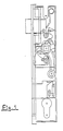
- the multi-point lock shown on the drawing comprises a lock casing 11, not specified further, which is designed for insertion in a door leaf.
- the lock casing 11 contains a main guide - rotary part 1 - which can turn on an axle 20 at right angles to the plane of the drawing.
- the rotary part 1 comprises two guide pins 21, 31 of which pin 21 is projecting into a first recess 23 of a main driver 2 which is vertically to and fro movable perpendicular to axle 20 which is extending through a second recess 27 in main driver 2.
- the dimensions of this recess are larger than that of axle 20 in order to allow linear movement of driver 2 perpendicular to axle 20. This is clearly shown in the drawing.
- the other guide pin 31 of rotary part 1 interacts with a recess 33 of a latch lever 4 that can be turned on said axle 20 and which is connected to a latch bolt 5 projecting from the lock casing 11 such that by turning the latch lever 4 the latch bolt 5 can be drawn into the lock casing 11 counterac- tiong the force of a spring 6.
- the lock comprises a draw bar drive 3 which can be turned on another axle 30 at right angles to the plane of the drawing.
- the draw bar drive 3 is provided with a pin 29 projecting into a hole 28 of the main driver 2 provided with a third recess 26 allowing its linear movement in respect to axle 30.
- the arrangement of these parts (especially shown in Fig. 6) is so chosen that by turning the rotary part 1 the main driver 2 is moved linearly effected by the interaction of guide pin 21 and the periphery of recess 23.
- the linear movement of the main driver 2 causes a rotation of draw bar drive 3 since pin 29 of bar drive 3 engages hole 28 of main driver 2.
- the draw bar drive 3 has a serration engaging a draw bar 7 which reciprocates when the draw bar drive 3 is turned.
- axle 20 of rotary part 1 is provided with a handle (not shown) for operating the lock.
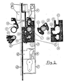
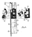
- the rotary part 1 is biased by a main spring 10 which tends to hold rotary part 1 in the neutral position shown in Figs. 2 and 4.
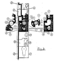
- the lock is unlocked by turning rotary part 1 through 26° as shown in Fig. 3. This turn will cause guide pin 21 of the rotary part 1 to come into contact with the upper portion of the peripheral edge 24 of recess 23 and forces main driver 2 upwards.
- the pin 29 of draw bar drive 3 engaging hole 28 of the main driver 2 then causes the draw bar drive 3 to turn clockwise so that the draw bar 7 is moved upwards.
- the other guide pin 31 of rotary part 1 will at the same time engage recess 33 of latch lever 4 and turn it clockwise.
- the latch bolt 5 is thereby drawn into the lock casing 11 against the effect of spring 6 so that the lock is unlocked.
- main spring 10 will move rotary part 1 to the neutral position as shown in Fig. 4, and spring 6 will force latch bolt 5 outwards.
- the recess 23 of the main driver 2 comprises sufficient space such that rotary part 1 can turn back in the neutral position without carrying the main driver 2 downwards.
- the latch bolt 5 can be drawn in again by the rotary part 1 being turned through 26° (Fig. 3).
- the guide pin 21 on the rotary part 1 will then only be shifted ineffectively in the recess 23 of the main driver 2.
- Locking is effected by turning rotary part 1 through 45° starting from the neutral position in the opposite direction (Fig. 5). During this turn guide pin 21 comes in contact with the lower portion 25 of the periphery of recess 23 thereby carrying main driver 2 downwards. This downward movement is transmitted to the draw bar 7 via draw bar drive 3 pin 29 of which engages the hole 28 of main driver 2.
- recess 23 of the main driver 2 is designed so that rotary part 1 can turn back in the neutral position without carrying the main driver upwards.
- Fig. 7 is a graphic representation of the relation between the movement of draw bar 7 and the turn of the rotary part 1 during locking.
- the attraction itself will take place when the draw bar has moved through 64% of the total movement.
Landscapes
- Engineering & Computer Science (AREA)
- Mechanical Engineering (AREA)
- Steering Devices For Bicycles And Motorcycles (AREA)
- Mechanical Control Devices (AREA)
Claims (1)
- Mehrfachschloß mit einer Zugstange (7), die zwischen einer Verschlußposition (sh. Fig. 5) und einer Offenposition (sh. Fig. 3) durch Drehung eines Zugstangenantriebs (3) hin- und herbewegt werden kann, und einem Handgriff zum Betätigen des Schlosses, dadurch gekennzeichnet, daß ein Drehteil (1), das mittels des Handgriffes um eine Achse (20) gedreht werden kann, einen Führungsstift (21) aufweist, der in eine Aussparung (23) eines linear bewegbaren Hauptmitnehmers (2) eingreift, so daß eine Drehung des Drehteils (1) ein Hin- und Herbewegen des Hauptmitnehmers (2) bewirkt, der mit einer Mitnehmerbohrung (28) versehen ist, in welche ein Stift (29) eingreift, der auf dem Zugstangenantrieb (3) angebracht ist, so daß die Hin- und Herbewegung des Hauptmitnehmers (2) eine Drehung des Zugstangenantriebs (3) bewirkt, wobei die Aussparung (23) des Hauptmitnehmers (2) so bemessen ist, daß eine Drehung des Drehteils (1) um einen vorbestimmten Winkel (45°) von einer neutralen Position den Hauptmitnehmer in eine extreme Position (sh. Fig. 5) bewegt und eine Drehung des Drehteils (1) um einen anderen vorbestimmten Winkel (26°), der erheblich kleiner als der erstgenannte vorbestimmte Winkel ist, von der neutralen Position in die andere Richtung den Hauptmitnehmer (2) in die entgegengesetzte extreme Position (sh. Fig. 3) bewegt.
Priority Applications (1)
| Application Number | Priority Date | Filing Date | Title |
|---|---|---|---|
| AT86902349T ATE59424T1 (de) | 1985-04-10 | 1986-04-09 | Mehrfachschloss. |
Applications Claiming Priority (2)
| Application Number | Priority Date | Filing Date | Title |
|---|---|---|---|
| DK160685A DK160685D0 (da) | 1985-04-10 | 1985-04-10 | Flerpunktlaas med ulige lukke- og aabnefunktion |
| DK1606/85 | 1985-04-10 |
Publications (2)
| Publication Number | Publication Date |
|---|---|
| EP0218654A1 EP0218654A1 (de) | 1987-04-22 |
| EP0218654B1 true EP0218654B1 (de) | 1990-12-27 |
Family
ID=8106483
Family Applications (1)
| Application Number | Title | Priority Date | Filing Date |
|---|---|---|---|
| EP19860902349 Expired EP0218654B1 (de) | 1985-04-10 | 1986-04-09 | Mehrfachschloss |
Country Status (4)
| Country | Link |
|---|---|
| EP (1) | EP0218654B1 (de) |
| DE (1) | DE3676619D1 (de) |
| DK (1) | DK160685D0 (de) |
| WO (1) | WO1986006130A1 (de) |
Families Citing this family (2)
| Publication number | Priority date | Publication date | Assignee | Title |
|---|---|---|---|---|
| AT394609B (de) * | 1989-01-03 | 1992-05-25 | Roto Frank Eisenwaren | Getriebe fuer drehkipptueren |
| US7604265B2 (en) * | 2004-11-04 | 2009-10-20 | Imperial Usa, Ltd. | Latch assembly for sliding doors |
Family Cites Families (2)
| Publication number | Priority date | Publication date | Assignee | Title |
|---|---|---|---|---|
| ES492714A0 (es) * | 1979-06-25 | 1980-12-16 | Schlegel Uk Ltd | Un dispositivo de cerradura de tres puntos |
| FR2484003A1 (fr) * | 1980-06-05 | 1981-12-11 | Rochman Henri | Dispositif de fermeture pour portes sujettes a gauchissement |
-
1985
- 1985-04-10 DK DK160685A patent/DK160685D0/da not_active IP Right Cessation
-
1986
- 1986-04-09 EP EP19860902349 patent/EP0218654B1/de not_active Expired
- 1986-04-09 DE DE8686902349T patent/DE3676619D1/de not_active Expired - Fee Related
- 1986-04-09 WO PCT/DK1986/000033 patent/WO1986006130A1/en not_active Ceased
Also Published As
| Publication number | Publication date |
|---|---|
| WO1986006130A1 (en) | 1986-10-23 |
| DE3676619D1 (de) | 1991-02-07 |
| EP0218654A1 (de) | 1987-04-22 |
| DK160685D0 (da) | 1985-04-10 |
Similar Documents
| Publication | Publication Date | Title |
|---|---|---|
| EP0661409B1 (de) | Schloss und Schlossvorrichtung für eine Tür oder ein fenster | |
| DE3853828T2 (de) | Verriegelungsvorrichtung. | |
| US4413849A (en) | Tool-operated flush-mountable latch | |
| US4662665A (en) | Auxiliary lock with an extensible device | |
| CA2124872A1 (en) | Lock Assembly | |
| EP2224081B1 (de) | Verschluss für Schiebetür oder -tor | |
| US4530528A (en) | Double action crib drop side lock | |
| CA2138987A1 (en) | Magnetic locks | |
| US4113294A (en) | Anti-theft clip | |
| GB1326871A (en) | Motor vehicle door latches | |
| US3159993A (en) | Mortise lock with latch bolt and locking bolt | |
| US4111020A (en) | Pick-resistant axial split-pin tumbler-type lock mechanism | |
| EP0376572A2 (de) | Bewegungsübertragungsvorrichtung für einen Türgriff | |
| GB2413822A (en) | Lock mechanism locked by a pivoting deadbolt | |
| US4326396A (en) | Plate tumbler for a cylinder lock mechanism | |
| WO1986006130A1 (en) | Multi-point lock | |
| CN210798508U (zh) | 一种门锁及其联动式解锁机构 | |
| CN212837223U (zh) | 一种轴向闭锁机构及锁具 | |
| JP4231595B2 (ja) | 施錠装置 | |
| KR200295259Y1 (ko) | 모티스 록킹장치 | |
| CN208329894U (zh) | 一种快速安装的锁芯构造 | |
| GB1440004A (en) | Locking means | |
| CN210858260U (zh) | 门锁及传动装置 | |
| CN221524505U (zh) | 一种锁具 | |
| CN112523607B (zh) | 一种门锁及其联动式解锁机构 |
Legal Events
| Date | Code | Title | Description |
|---|---|---|---|
| PUAI | Public reference made under article 153(3) epc to a published international application that has entered the european phase |
Free format text: ORIGINAL CODE: 0009012 |
|
| 17P | Request for examination filed |
Effective date: 19861220 |
|
| AK | Designated contracting states |
Kind code of ref document: A1 Designated state(s): AT BE CH DE FR GB IT LI LU NL SE |
|
| 17Q | First examination report despatched |
Effective date: 19880212 |
|
| GRAA | (expected) grant |
Free format text: ORIGINAL CODE: 0009210 |
|
| AK | Designated contracting states |
Kind code of ref document: B1 Designated state(s): AT BE CH DE FR GB IT LI LU NL SE |
|
| PG25 | Lapsed in a contracting state [announced via postgrant information from national office to epo] |
Ref country code: IT Free format text: LAPSE BECAUSE OF FAILURE TO SUBMIT A TRANSLATION OF THE DESCRIPTION OR TO PAY THE FEE WITHIN THE PRE;WARNING: LAPSES OF ITALIAN PATENTS WITH EFFECTIVE DATE BEFORE 2007 MAY HAVE OCCURRED AT ANY TIME BEFORE 2007. THE CORRECT EFFECTIVE DATE MAY BE DIFFERENT FROM THE ONE RECORDED.SCRIBED TIME-LIMIT Effective date: 19901227 Ref country code: SE Free format text: THE PATENT HAS BEEN ANNULLED BY A DECISION OF A NATIONAL AUTHORITY Effective date: 19901227 Ref country code: LI Effective date: 19901227 Ref country code: NL Effective date: 19901227 Ref country code: CH Effective date: 19901227 Ref country code: FR Effective date: 19901227 Ref country code: BE Effective date: 19901227 Ref country code: AT Effective date: 19901227 |
|
| REF | Corresponds to: |
Ref document number: 59424 Country of ref document: AT Date of ref document: 19910115 Kind code of ref document: T |
|
| REF | Corresponds to: |
Ref document number: 3676619 Country of ref document: DE Date of ref document: 19910207 |
|
| PG25 | Lapsed in a contracting state [announced via postgrant information from national office to epo] |
Ref country code: GB Effective date: 19910409 |
|
| REG | Reference to a national code |
Ref country code: CH Ref legal event code: PL |
|
| PG25 | Lapsed in a contracting state [announced via postgrant information from national office to epo] |
Ref country code: LU Free format text: LAPSE BECAUSE OF NON-PAYMENT OF DUE FEES Effective date: 19910430 |
|
| NLV1 | Nl: lapsed or annulled due to failure to fulfill the requirements of art. 29p and 29m of the patents act | ||
| EN | Fr: translation not filed | ||
| PLBE | No opposition filed within time limit |
Free format text: ORIGINAL CODE: 0009261 |
|
| STAA | Information on the status of an ep patent application or granted ep patent |
Free format text: STATUS: NO OPPOSITION FILED WITHIN TIME LIMIT |
|
| GBPC | Gb: european patent ceased through non-payment of renewal fee | ||
| 26N | No opposition filed | ||
| PG25 | Lapsed in a contracting state [announced via postgrant information from national office to epo] |
Ref country code: DE Effective date: 19920201 |
|
| ITTA | It: last paid annual fee |