EP0218777A2 - Procédé pour le thermoformage continu de tissus tubulaires doubles et appareil pour sa réalisation - Google Patents
Procédé pour le thermoformage continu de tissus tubulaires doubles et appareil pour sa réalisation Download PDFInfo
- Publication number
- EP0218777A2 EP0218777A2 EP86104466A EP86104466A EP0218777A2 EP 0218777 A2 EP0218777 A2 EP 0218777A2 EP 86104466 A EP86104466 A EP 86104466A EP 86104466 A EP86104466 A EP 86104466A EP 0218777 A2 EP0218777 A2 EP 0218777A2
- Authority
- EP
- European Patent Office
- Prior art keywords
- fabric
- mandrel
- mandrels
- station
- thermoforming
- Prior art date
- Legal status (The legal status is an assumption and is not a legal conclusion. Google has not performed a legal analysis and makes no representation as to the accuracy of the status listed.)
- Granted
Links
- 239000004744 fabric Substances 0.000 title claims abstract description 118
- 238000003856 thermoforming Methods 0.000 title claims abstract description 43
- 238000000034 method Methods 0.000 title claims abstract description 32
- 230000000903 blocking effect Effects 0.000 claims abstract description 25
- 238000004519 manufacturing process Methods 0.000 claims abstract description 15
- 238000001816 cooling Methods 0.000 claims abstract description 12
- 229920000728 polyester Polymers 0.000 claims abstract description 8
- 238000005520 cutting process Methods 0.000 claims abstract description 4
- 229920005989 resin Polymers 0.000 claims description 10
- 239000011347 resin Substances 0.000 claims description 10
- 238000005096 rolling process Methods 0.000 claims description 6
- 239000002759 woven fabric Substances 0.000 claims description 5
- 238000002844 melting Methods 0.000 claims description 3
- 230000008018 melting Effects 0.000 claims description 3
- 229920001187 thermosetting polymer Polymers 0.000 claims description 3
- 239000012530 fluid Substances 0.000 claims description 2
- 230000002452 interceptive effect Effects 0.000 claims description 2
- 239000012811 non-conductive material Substances 0.000 claims description 2
- 229920001169 thermoplastic Polymers 0.000 claims description 2
- 239000004416 thermosoftening plastic Substances 0.000 claims description 2
- 230000002093 peripheral effect Effects 0.000 claims 1
- 239000000835 fiber Substances 0.000 description 15
- 239000000463 material Substances 0.000 description 6
- 239000011521 glass Substances 0.000 description 5
- 239000002253 acid Substances 0.000 description 3
- 238000010586 diagram Methods 0.000 description 3
- 238000003780 insertion Methods 0.000 description 3
- 230000037431 insertion Effects 0.000 description 3
- 238000003860 storage Methods 0.000 description 3
- 239000004743 Polypropylene Substances 0.000 description 2
- 239000011149 active material Substances 0.000 description 2
- 230000001458 anti-acid effect Effects 0.000 description 2
- 239000000919 ceramic Substances 0.000 description 2
- YADSGOSSYOOKMP-UHFFFAOYSA-N dioxolead Chemical compound O=[Pb]=O YADSGOSSYOOKMP-UHFFFAOYSA-N 0.000 description 2
- 230000000694 effects Effects 0.000 description 2
- 238000000605 extraction Methods 0.000 description 2
- 238000001914 filtration Methods 0.000 description 2
- 238000010438 heat treatment Methods 0.000 description 2
- 230000036961 partial effect Effects 0.000 description 2
- ISWSIDIOOBJBQZ-UHFFFAOYSA-N phenol group Chemical group C1(=CC=CC=C1)O ISWSIDIOOBJBQZ-UHFFFAOYSA-N 0.000 description 2
- 238000006116 polymerization reaction Methods 0.000 description 2
- 229920001155 polypropylene Polymers 0.000 description 2
- 230000002829 reductive effect Effects 0.000 description 2
- 230000000717 retained effect Effects 0.000 description 2
- 238000009958 sewing Methods 0.000 description 2
- 239000002699 waste material Substances 0.000 description 2
- 238000003466 welding Methods 0.000 description 2
- 229910000978 Pb alloy Inorganic materials 0.000 description 1
- 238000004458 analytical method Methods 0.000 description 1
- 230000002547 anomalous effect Effects 0.000 description 1
- 230000000181 anti-adherent effect Effects 0.000 description 1
- 239000003911 antiadherent Substances 0.000 description 1
- 230000009172 bursting Effects 0.000 description 1
- 239000003795 chemical substances by application Substances 0.000 description 1
- 230000006835 compression Effects 0.000 description 1
- 238000007906 compression Methods 0.000 description 1
- 238000010924 continuous production Methods 0.000 description 1
- 239000013256 coordination polymer Substances 0.000 description 1
- 239000013078 crystal Substances 0.000 description 1
- 238000009792 diffusion process Methods 0.000 description 1
- 239000003792 electrolyte Substances 0.000 description 1
- 238000005516 engineering process Methods 0.000 description 1
- 230000004927 fusion Effects 0.000 description 1
- 238000009434 installation Methods 0.000 description 1
- 238000010409 ironing Methods 0.000 description 1
- 230000001788 irregular Effects 0.000 description 1
- 238000005304 joining Methods 0.000 description 1
- 229910000464 lead oxide Inorganic materials 0.000 description 1
- 230000000670 limiting effect Effects 0.000 description 1
- 239000007788 liquid Substances 0.000 description 1
- 230000014759 maintenance of location Effects 0.000 description 1
- 238000000465 moulding Methods 0.000 description 1
- 230000007935 neutral effect Effects 0.000 description 1
- 239000004745 nonwoven fabric Substances 0.000 description 1
- 230000003647 oxidation Effects 0.000 description 1
- 238000007254 oxidation reaction Methods 0.000 description 1
- YEXPOXQUZXUXJW-UHFFFAOYSA-N oxolead Chemical compound [Pb]=O YEXPOXQUZXUXJW-UHFFFAOYSA-N 0.000 description 1
- 230000000149 penetrating effect Effects 0.000 description 1
- 239000004033 plastic Substances 0.000 description 1
- 229920003023 plastic Polymers 0.000 description 1
- -1 polypropylene Polymers 0.000 description 1
- 239000007774 positive electrode material Substances 0.000 description 1
- 238000002360 preparation method Methods 0.000 description 1
- 238000003825 pressing Methods 0.000 description 1
- 239000013049 sediment Substances 0.000 description 1
- 238000004904 shortening Methods 0.000 description 1
- 229920002379 silicone rubber Polymers 0.000 description 1
- 239000004945 silicone rubber Substances 0.000 description 1
- 238000004513 sizing Methods 0.000 description 1
- 239000000126 substance Substances 0.000 description 1
- 229920005992 thermoplastic resin Polymers 0.000 description 1
- 239000002023 wood Substances 0.000 description 1
Images


Classifications
-
- B—PERFORMING OPERATIONS; TRANSPORTING
- B29—WORKING OF PLASTICS; WORKING OF SUBSTANCES IN A PLASTIC STATE IN GENERAL
- B29D—PRODUCING PARTICULAR ARTICLES FROM PLASTICS OR FROM SUBSTANCES IN A PLASTIC STATE
- B29D23/00—Producing tubular articles
-
- B—PERFORMING OPERATIONS; TRANSPORTING
- B01—PHYSICAL OR CHEMICAL PROCESSES OR APPARATUS IN GENERAL
- B01D—SEPARATION
- B01D39/00—Filtering material for liquid or gaseous fluids
- B01D39/14—Other self-supporting filtering material ; Other filtering material
- B01D39/16—Other self-supporting filtering material ; Other filtering material of organic material, e.g. synthetic fibres
- B01D39/1607—Other self-supporting filtering material ; Other filtering material of organic material, e.g. synthetic fibres the material being fibrous
- B01D39/1623—Other self-supporting filtering material ; Other filtering material of organic material, e.g. synthetic fibres the material being fibrous of synthetic origin
- B01D39/163—Other self-supporting filtering material ; Other filtering material of organic material, e.g. synthetic fibres the material being fibrous of synthetic origin sintered or bonded
-
- B—PERFORMING OPERATIONS; TRANSPORTING
- B29—WORKING OF PLASTICS; WORKING OF SUBSTANCES IN A PLASTIC STATE IN GENERAL
- B29C—SHAPING OR JOINING OF PLASTICS; SHAPING OF MATERIAL IN A PLASTIC STATE, NOT OTHERWISE PROVIDED FOR; AFTER-TREATMENT OF THE SHAPED PRODUCTS, e.g. REPAIRING
- B29C61/00—Shaping by liberation of internal stresses; Making preforms having internal stresses; Apparatus therefor
- B29C61/02—Thermal shrinking
- B29C61/025—Thermal shrinking for the production of hollow or tubular articles
-
- H—ELECTRICITY
- H01—ELECTRIC ELEMENTS
- H01M—PROCESSES OR MEANS, e.g. BATTERIES, FOR THE DIRECT CONVERSION OF CHEMICAL ENERGY INTO ELECTRICAL ENERGY
- H01M4/00—Electrodes
- H01M4/02—Electrodes composed of, or comprising, active material
- H01M4/64—Carriers or collectors
- H01M4/70—Carriers or collectors characterised by shape or form
- H01M4/76—Containers for holding the active material, e.g. tubes, capsules
- H01M4/765—Tubular type or pencil type electrodes; tubular or multitubular sheaths or covers of insulating material for said tubular-type electrodes
-
- B—PERFORMING OPERATIONS; TRANSPORTING
- B01—PHYSICAL OR CHEMICAL PROCESSES OR APPARATUS IN GENERAL
- B01D—SEPARATION
- B01D2239/00—Aspects relating to filtering material for liquid or gaseous fluids
- B01D2239/10—Filtering material manufacturing
-
- Y—GENERAL TAGGING OF NEW TECHNOLOGICAL DEVELOPMENTS; GENERAL TAGGING OF CROSS-SECTIONAL TECHNOLOGIES SPANNING OVER SEVERAL SECTIONS OF THE IPC; TECHNICAL SUBJECTS COVERED BY FORMER USPC CROSS-REFERENCE ART COLLECTIONS [XRACs] AND DIGESTS
- Y02—TECHNOLOGIES OR APPLICATIONS FOR MITIGATION OR ADAPTATION AGAINST CLIMATE CHANGE
- Y02E—REDUCTION OF GREENHOUSE GAS [GHG] EMISSIONS, RELATED TO ENERGY GENERATION, TRANSMISSION OR DISTRIBUTION
- Y02E60/00—Enabling technologies; Technologies with a potential or indirect contribution to GHG emissions mitigation
- Y02E60/10—Energy storage using batteries
Definitions
- the present invention refers to a procedure involving continuous hot forming and stiffening of a double tubular fabric and a device for the realization of such procedure.
- the procedure of the present invention is particularly suited for the production of multitubular sheaths for the retention of the action material in the electrods of industrial lead-acid storage batteries, namely traction or stationary batteries.
- multitubular sheaths for industrial batteries it could possibly be employed advantageously in the production of semistiff selfbearing multitubular fabrics for the filtration of gazes, liquids, sediments, etc.
- Industrial lead-acid storage batteries are known to be provided with positive tubular plates which offer several advantages as compared to the traditional type of pasted flat grids. In particular these are characterized by a longer lifetime, measured in terms of cycles of charge and discharge. This greater endurance is believed to be due to the fact that the positive active material, which when charged consists of contiguous crystals of lead dioxide, is retained as crystalline coherence and adhesion against the grid's plug thanks to the pressure produced by the antiacid and porous tubes which inhibit the breaking up, the transmigration and therefore the shedding and the drop towards the bottom of the container.
- the positive tubular plates usually consist of a certain number (usually between 15 and 19) of porous semistiff tubes with an external diameter of 9 mm made of electrolyte, a synthetic antiacid and non-polluting material.
- Such tubes are arranged side by side at a constant pitch, adjacent and parallel to one another, each tube being prefilled with a thin central plug of a specific lead alloy and then completely filled with lead-oxide.
- the tubes and the sheaths are made of different materials: resin-bonded spun glass fabric or braided glass fabric covered by an external perforated laminate sheath of polyvynil cloride having a support purpose, or a fabric of polyester fibers or of mixed polyster-polypropylene fibers.
- the multitubular fabric which is used for the production of the tubular sheath can be obtained either directly by means of a loom utilizing polyester, glass, resin-bonded glass or mixed fibers, or by sewing together two layers of woven fabric or two layers of thin felt.
- the tubes are obtained by joining means welding, sewing or other means the two overlapped layers along parallel lines at regular and constant distance.
- thermoforming mandrel operating within a furnace or heating area where the thermoforming (setting of the tube's shape and dimensions) occurs.
- each cane of the double tubular fabric gets filled by a proportionately fit mandrel and is transferred with it in the furnace at the established optimal temperature. Thermoforming takes place as the fabric shrinks and moulds into the shape of the mandrel within, though without a movement relative to the mandrel and without relative velocity between the two elements.
- a continuous transverse tubular carpet is the outcome from which strips of 15 to 19 tubes are cut in length according to the desired measure.
- thermoforming occurs without longitudinal tension, thus conferring high degree of quality and consistency to the product.
- the system having the fixed mandrel within the furnace consists of an apparatus in which 15 or 19 mandrels are engaged at one end while they float at the other, as they are supported and kept at the distance necessary to obtain the required pitch between tubes.
- the tubular fabric is passed continuously over them after having inserted one end of a fixed mandrel in each of the corresponding canes of the soft fabric.
- thermoforming is obtained by dragging the sliding fabric over the mandrels through the apparatus' furnace, where the fabric takes the shape of the mandrels within. In this case thermoforming occurs on the mandrels with a rather high relative velocity between sliding fabric and the fixed mandrels underneath.
- the advantages of this apparatus are: - a lower cost, because the apparatus is much simpler that the other system - lower labor needed to operate the apparatus - less wastes because the strips of fabric can be produced exactly of 15 or 19 tubes without having to discard the 16th or the 20th, and because the sheaths can be cut in the dimension needed without scraps.
- thermoforming in fact cannot result as perfect and uniform because of the axial sliding over the mandrel at the same time of the tightening of the fabers around itself.
- a deformation of varying degree is therefore produced on the fabric undergoing the process of thermoforming, and because of the necessity of a high speed production, especially when thermoshrinking fibers are used, a residual thermoshrinkage results axially on the fibers.
- an unrecovered tension occurs and the sheaths filled and mounted on the battery are able to complete their adjustement phase and their thermic axial shrinkage as soon as a high temperature is developed for various reasons inside the operating battery.
- the fixed mandrel devices include: means to feed the fabric; a blocking unit for the mandrels; a system to slide the fabric; a furnace for the thermoforming and stiffening; a cooling-finish and possibly cutting system.
- the critical portion of such fixed mandrel devices concerns the blocking system for the mandrels and the insufficient ability to reduce friction to the minimum in both thermoforming and blocking stations. In particular there is the friction generated by the sliding of the fabric advancement.
- the different parts of the device are designed to comply with the advancement friction which sometime, if not properly built, they create themselves.
- the French patent number 1414272 describes a device with fixed mandrels where the blocking of the mandrel is achieved by means of a bottle-neck narrowing located in a spot on the mandrel itself and by means of a pair of blocking counterrollers which are free to rotate. These are placed over the mandrel narrowing thus preventing the passages of the end portion of the mandrel itself on the opposite side of the paired rollers.
- the mandrel's neck is brought back at once toward the counterrollers and it penetrates into them pressing against the fabric thus preventing it from sliding.
- German patent number 3238838 also proposes an "S" shaped system for the blocking of the mandrel, but even in this case the already elucidated problems persist if not increased as the fabric runs on a longer distance over the mandrel and is pressed by the advancing rollers against the mandrel itself.
- British patent number 1574722 and 1551798 describe a procedure and a product which do not lack difficulties. More specifically the British patent number 1574722 states that if the battery works in a warm environment, such as the tropics, the finished product, that is the sheath, could present a loss of dimensional stability which could endanger the life of the battery itself. An attempt to face this problem has been made through the utilization of a fourfold fabric which has an additional external layer on both sides for a greater mechanical support and an internal filtering layer.
- the present invention aims at the realization of an apparatus with simple fixed mandrels capable of producing a multitubular sheath at great production speed and low costs which would be particularly suited to bear high temperatures and well as heavy operating conditions.
- Another objective of the present invention is to provide a procedure for the production of multitubular sheaths and in particular those bound to be utilized in the lead-acid industrial batteries with no residual tensions and a device for the actualization of such procedure.
- An additional objective of the present invention is the creation at low installation and operating cost of a multitubular sheath with a very stable structure, which offers a high porosity and at the same time a high compactness of the fabric.
- these and other objectives are obtained through a procedure that ulitizes a fixed mandrel in which a soft double tubular fabric is advanced continously with minimum friction on a set number of mandrels, previously inserted at one end of the fabric, which are held fixed on the side where the soft fabric is fed by means of a system of roller-bearing.
- This soft fabric can possibly be impregnated with thermoplastic thermostiffening resins or with resins of phenolic base produced with high tenacity twisted multiple filaments that are thermofixed in the direction of advancement of the fabric.
- Such system of engaging prevents the mandrels to be pulled inside the device by the friction forces exerted by them on the fabric that is shape-formed in the hot portion of the furnace and that tightens around them.
- This roller-bearing fixing system grants the simple flow without rolling friction and with pure revolving friction in a critical spot where the fabric is retained with strength by the mandrel blocking section. After the mandrel's revolving section the fabric runs through the thermoforming area, where the fabric shrinks over the mandrels and the eventual size contained in it polymerize and/or condensate without relevant or ununiform tensions.
- the strip is then cooled by the action of low temperature of fluids. Once it becomes perfectly rigid it is cut into pieces of the required length.
- the multitubular sheath used in the here present invention process involves continuous and high tenacity multifilament yarns which run parallel to the central axis of each tube. The yarns are already prefixed they have no residual theremoreturn, have a high degree of elasticity regarding deformations below 5% and they are stabilized and stiffened through a treatment of torsion and thermofixing at high temperature.
- the existance of these yarns allows to exert axially a perfectly elastic traction of the fabric without producing local non reversable deformations.
- the required degree of elasticity of the yarn is given by an adequate number of torsions per centimetre.
- the multifilament yarns consist of a great number of single equal and parallel filaments that allow to confer different characteristics to the yarn through suitable torsion.
- multifilament yarns which have undergone a high torsion allows also to obtain multitubular sheaths with a great fabric compactness and at the same time a high porosity. These combined characteristics provide the sheath with a great resistance to oxidation, due to the large number of threads per square centimetre.
- the high porosity is due to the fact that under torsion the thread becomes compact and is able to conserve a shape with elliptical or oval section instead of being flattened out on the mandrel. Therefore it is possible to insert more threads per linear centimetre fora given yarn denier. The result is a highly resistant compact and porous fabric.
- the multitubular fabric to be shape-formed is composed of non woven fabrics which have been sewn together or when the fabric is made of short fibers arranged along the direction of the tube's axis and held together by appropriate resins or by treatment that cause a partial fusion of part of the fabrics fibers, the traction exerted in dragging the fabric over the mandrels causes permanent deformations if the stresses get over a certain value, easily reached when operating a high temperature.
- a multitubular sheath consisting only of high tenacity multifilament yarns, preferably of polester, arranged vertically to the tube and parallel to its central axis.
- These yarns are adequately twisted with a high torsion value, they are thermofixed and preferably treated with phenolic, epoxidic or other resins which will increase their stiffness and eliminate their thermo-return even at temperatures near their melting point (200-230°).
- Resin-bonded chemical glass filaments could also be employed with less satisfying results.
- the multitubular sheaths can consist of either polyster thermoshrinking filaments or mixed short fibers threads containing thermoshrinking polyster and polypropylene which causes the bonding and stiffing of the polyster fibers when exposed to high temperatures.
- the present invention refers also to the continuous high speed hot thermoforming process of a soft tubular fabric which takes the shape of a stiff self-bearing multitubular sheath consisting of numerous equal and adjacent tubes attached to each other. The major characteristics of such procedure is the sliding without relevant friction of the fabric around the mandrels which in turn are engaged at one end by a small and simple system of roller bearings that are fixed opposite to each other on the mandrel itself and by a couple of counter-rollers, free to rotate around their axis.
- the two ball-bearings meet the two free rollers and by rotating they allow the fabric to slide smoothly between them. In this position friction is reduced to revolving friction at the tangency of the two sets.
- the device used for the realization of such procedure is also one of the objectives of the present invention, and it consists of the following parts: a feeding station; a station for the blocking of the mandrels; means for the advancement of the fabric; a furnace for thermoforming and polymerization; if necessary a forced cooling system; and eventually a station for the transveral cutting of the continuous semi-stiff multitubular strip produced.
- the feeding station can be of any kind and generally a cloth unwinder is used.
- Means for the strip advancement consist of pressure rolls, due to lack of relevant frictions, in the known art these means consisted of long needles or clasp systems on the strip sides.
- the blocking of the mandrels is obtained by mean of roll bearings inserted in each mandrel.
- the mandrel is generally two meters long, has a circular section end and an initial portion of rectangular section.
- the thermoforming procedure includes the feeding of the soft fabric comprising a 15 or 19 parallel and adjacent canes; the insertion of a thermoforming mandrel in each cane and the sliding of the fabric around the fixed mandrels into a thermoforming furnace.
- thermoforming device which is the object of the present invention, we report below its detailed description and some diagrams of reference which illustrate the apparatus in a schemetic but not limiting exemplification.
- Figure 1 illustrates in a schematic way the sequence of the stations for the thermoforming treatment of a multitubular soft woven fabric consisting of non thermoshrinkable multifilament yarns or preshrinked yarns along the length of the fabric.
- the multitubular fabric eventually impregnated with thermosetting resins or with resins that can be polycondensed with heat is collected by bobbins (Ti) that can be loaded within the supports of the feeding station A.
- the fabric is fitted (manually at the start of the process) on the crown of the selflocking mandrels in station B, dragged by the advancement station C, and sliding over the mandrels it is fed into the thermoshrinking and thermoforming station D.
- the dragging system in station C can be placed either before or after the termoforming station D.
- the fabric is passed through station E supplied with a forced cooling system and passed then to a station F where the strips are cut transversally accordingly to the dimensions needed for the sheaths.
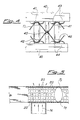
- Figure 2 represents a longitudinal section of the blocking station B where the mandrels are fixed in relation to the thermoforming furnace D without creating ununiformally distributed friction along the width of the fabric.
- the strip of the produced semirigid fabric is generally made of 15 to 19 parallel tubes which must have a stable and correct measure, a constant pitch between tubes and seams on the same plane. This is achieved by using a mandrel(3) which is shaped in an indifferent way at the end in the station D and rectangularly shaped (Si) toward the blocking station B.
- the rectangular or polygonal shape is suited to contain two roller bearing 1 and 2. These bearings rotate when pulled by the sliding fabric until they collide with free counterrollers 7 and 8 on which rest 9 and 10 causing their rotation at equal periferal velocity.
- the counterrollers 7 and 8 are placed at opposite sides of the fabric, their relative circumferences are distant from the external diameter of the mandrel, and their rotation axis are on a plane perpendicular or inclined in relation to the elongation axis of the fabric.
- the projection of the roller-bearings 1 and 2 and the profiling of the inetermediate sections Sf allow the fabric's seams to be aligned on the intertaxes which are expected for the end portion.
- the fabric remains soft and it never curls.
- Figure 3 represents the cross section of counter-rollers 7 and 8, which have two mouldings 11 responsible for the local contact 9 and 10 and for the lateral adjustement forward of the fabric necessary for the constant pitch P of two contiguous seams.
- roller beraings 1 and 2 can be bearings with different profiles even though a cylindrical one is preferred.
- a meridian profile with laterally troncated ellipse within the channels 11 that are extended to the seams can be used.
- Counter rollers 7 and 8 overlapped and parallel in neutral have a surface grooved at of regular intervals and preferably elliptically moulded grooves with the minor axis of the ellipse equal to the pitch of the finished sheaths and the long axis increased of a lenght sufficient to pull slightly the soft fabric; the profile of such grooves contrast with the transversal profile of the roller-beraings which should preferably be elliptical, with axis on the mandrel and should interfere with those rollers.
- the roller bearing can be fabricated in antiscuff material with or without pivots or rolling elements, or they can be made of spherical or roller micro-bearing.
- two more spherical revolving bearings 45 lead the mutlitubular fabric maintaining the predetermined pitch between tubes. These spheres project for at least a third of their diameter from the mandrel's profile.
- the blocking station of the mandrels can be formed by a pair of parallel overlapping bars with more spheres set in special fixtures carved in the bars on the side facing the other bar.
- the fixtures must be spaced at adequate intervals so that at least two spheres contrast with the elliptical profile bearing or with a sphere set into the mandrels.
- thermoforming station D can have a rather high temperature (200°C for polyester fibers) with a forced hot air which facilitates the complete shrinkage of the cross shrinkage yarns, without affecting the mechanical characteristics of the axial non-shrinkage yarns.
- thermoforming systems involving the heating of mandrel 3 either a method of inner resistence or inducation can be used.
- Infrared wave systems can also be utilized: in this case the adequate choice of the position of the lamps (possibly in ceramic) and the temperature of the lamps (600-800°C) can allow a high speed production.
- thermoforming station When in the thermoforming station it is used a multitubular fabric composed in part or solely of polyester, there can be a loss in tenacity due to two causes: temperature and presence of a metallic mandrel.
- Polyester is infact known to have a good resistance to temperature in hot air while it shows a rapid drop in tenacity when put into direct contact of metallic surfaces at the same temperature (ironing effect). In the literature these phenomena, and specificly the temperature fields in which such phenomena occur, are described.
- high resistance multitubular sheaths which have a high tenacity and high resistance to bursting even after thermoforming, are obtained (section D figure 1) utilizing a mandrel of a non-conductive material, as wood, ceramic, etc. whose surface has been adequately smoothed to favour the sliding of the fabric.
- Section E of figure 1 provides a cooling station. Such cooling station is not necessary when the fabric is impregnated with thermosetting resins.
- thermoforming device in order to obtain in a continuous, and rapid way a low cost multitubular sheaths it is better to use in the thermoforming device a high efficiency cooling system.
- a high efficiency cooling system Such system is illustrated in details in figure 5 where the final section Sf, of one of the thermoforming mandrels is magnified.
- the mandrel has a geometrical shape that is exactly calibrated as to give tube the shape required, and it shows a series of circular holes which allow the flow of low temperature air (preferably minus 20°C to +5°C). This air passes through the mesh of the fabric Ti inside the pierced mandrel Sf and is spread in every direction to cool both mandrel and the fabric Tf which forms the surface of the mutlitubular sheath's tube.
- the high tenacity thermoshrinking yarns are arranged transversally in relation to the advancement system, while the high tenacity thermostable yarns with a high torsion value are arrange longitudinally, that is along the advancement direction of the device.
- the fabric can have 18 yarns/cm transversally and 18 yarns/cm with a torsion of 300 twists/inch longitudinally.
- the fabric is then impregnated with solution of acrilic base resin having a density of 1.10 kg/dm3, a viscosity of 3000 CP (Brookfield: II/6) and a pH of 7.5;
- the fabric is fed on a device made for example of 19 thermoforming mandrels, that are 3 meters in lenght.
- Each mandrel is composed of various contiguous sections. Each of these sections arranged in sequence, can have a geometrical shape different from the adjacent ones and can be made of different material and shape from the two adjacent sections.
- the terminal portion of each mandrel must have the requested section, generally circular for standard sheaths.
- the rectangular initial end can have sides of 8 mm and 6 mm.
- the sides measuring 6 mm are provided with two roller-bearing 1 and 2 of figure 2 and figure 3 of the diameter of 9 mm.
- the two roller-bearings are arranged so that their rotation axis is parallel to the 6 mm face.
- the roller bearings are not aligned in relation to the 8 mm face but they are shifted so that the bearing 1 gets to be behind the bearing 2.
- thermoforming mandrels 3 are inserted one into each of the corresponding cane of the multitubular soft fabric.
- Tha fabric is then pulled forward manually into position C of figure 1.
- the blocking rollers are lowered and the mechanism is started manually until the thermoforming occurs in section D and the cooling and stiffening of the multitubular sheath occurs in E.
- advancement system C is able to grab the sheath, to cause the sliding of the fabric on the mandrels and to allow the starting and the continuous production until the end of the roll of fabric.
Landscapes
- Engineering & Computer Science (AREA)
- Chemical & Material Sciences (AREA)
- Chemical Kinetics & Catalysis (AREA)
- Mechanical Engineering (AREA)
- Electrochemistry (AREA)
- General Chemical & Material Sciences (AREA)
- Manufacturing & Machinery (AREA)
- Physics & Mathematics (AREA)
- Thermal Sciences (AREA)
- Treatment Of Fiber Materials (AREA)
- Meat, Egg Or Seafood Products (AREA)
- Blow-Moulding Or Thermoforming Of Plastics Or The Like (AREA)
Priority Applications (1)
| Application Number | Priority Date | Filing Date | Title |
|---|---|---|---|
| AT86104466T ATE69198T1 (de) | 1985-10-16 | 1986-04-02 | Verfahren zum kontinuierlichen warmformen doppelrohrfoermiger gewebe und vorrichtung fuer seine durchfuehrung. |
Applications Claiming Priority (2)
| Application Number | Priority Date | Filing Date | Title |
|---|---|---|---|
| IT22510/85A IT1185451B (it) | 1985-10-16 | 1985-10-16 | Procedimento per la termoformatura in continuo di tessuti doppi tubolari e dispositivo per la sua realizzazione |
| IT2251085 | 1985-10-16 |
Publications (3)
| Publication Number | Publication Date |
|---|---|
| EP0218777A2 true EP0218777A2 (fr) | 1987-04-22 |
| EP0218777A3 EP0218777A3 (en) | 1989-03-15 |
| EP0218777B1 EP0218777B1 (fr) | 1991-11-06 |
Family
ID=11197235
Family Applications (1)
| Application Number | Title | Priority Date | Filing Date |
|---|---|---|---|
| EP86104466A Expired - Lifetime EP0218777B1 (fr) | 1985-10-16 | 1986-04-02 | Procédé pour le thermoformage continu de tissus tubulaires doubles et appareil pour sa réalisation |
Country Status (4)
| Country | Link |
|---|---|
| EP (1) | EP0218777B1 (fr) |
| AT (1) | ATE69198T1 (fr) |
| DE (1) | DE3682363D1 (fr) |
| IT (1) | IT1185451B (fr) |
Cited By (4)
| Publication number | Priority date | Publication date | Assignee | Title |
|---|---|---|---|---|
| EP0383044A1 (fr) * | 1989-01-27 | 1990-08-22 | TERMAR S.r.l. | Feuilles multitubulaires à structure renforcée pour électrodes de batteries plomb-acide |
| EP0589126A1 (fr) * | 1992-09-25 | 1994-03-30 | Albany International Corp. | Elément filtrant à fibres rigidifiés |
| EP3136476A1 (fr) * | 2015-10-09 | 2017-03-01 | Mecondor S.A. | Manchette multitubulaire pour batteries plomb-acide |
| CN110785878A (zh) * | 2017-06-29 | 2020-02-11 | 日立化成株式会社 | 活性物质保持用管、电极和铅蓄电池 |
Family Cites Families (5)
| Publication number | Priority date | Publication date | Assignee | Title |
|---|---|---|---|---|
| DE1283490B (de) * | 1964-10-15 | 1968-11-21 | Textiltech Forsch | Vorrichtung zum Heissformen und Versteifen einer aus mehreren nebeneinanderliegenden, zusammenhaengenden Schlaeuchen bestehenden Bahn |
| IT1079489B (it) * | 1976-03-04 | 1985-05-13 | Chloride Group Ltd | Procedimento ed apparecchio per la produzione di involucri multitubolari in particolare per batterie di accumulatori elettrici |
| GB1551798A (en) * | 1976-08-25 | 1979-08-30 | Chloride Group Ltd | Multitubular sheats |
| AT374304B (de) * | 1980-11-18 | 1984-04-10 | Huyck Fez Ges M B H | Vorrichtung zum formen einer mit einem thermoplastischen stoff impraegnierten materialbahn |
| GB2128538B (en) * | 1982-10-21 | 1986-05-08 | Akkumulator Es Szarazelemgyar | Heating and shaping tubular material |
-
1985
- 1985-10-16 IT IT22510/85A patent/IT1185451B/it active
-
1986
- 1986-04-02 EP EP86104466A patent/EP0218777B1/fr not_active Expired - Lifetime
- 1986-04-02 AT AT86104466T patent/ATE69198T1/de not_active IP Right Cessation
- 1986-04-02 DE DE8686104466T patent/DE3682363D1/de not_active Expired - Fee Related
Cited By (6)
| Publication number | Priority date | Publication date | Assignee | Title |
|---|---|---|---|---|
| EP0383044A1 (fr) * | 1989-01-27 | 1990-08-22 | TERMAR S.r.l. | Feuilles multitubulaires à structure renforcée pour électrodes de batteries plomb-acide |
| EP0589126A1 (fr) * | 1992-09-25 | 1994-03-30 | Albany International Corp. | Elément filtrant à fibres rigidifiés |
| EP3136476A1 (fr) * | 2015-10-09 | 2017-03-01 | Mecondor S.A. | Manchette multitubulaire pour batteries plomb-acide |
| EP3136476B1 (fr) | 2015-10-09 | 2019-02-13 | Mecondor S.A. | Manchette multitubulaire pour batteries plomb-acide |
| CN110785878A (zh) * | 2017-06-29 | 2020-02-11 | 日立化成株式会社 | 活性物质保持用管、电极和铅蓄电池 |
| EP3648209A4 (fr) * | 2017-06-29 | 2020-07-15 | Hitachi Chemical Company, Ltd. | Tube de maintien de matériau actif, électrode et accumulateur au plomb |
Also Published As
| Publication number | Publication date |
|---|---|
| ATE69198T1 (de) | 1991-11-15 |
| IT1185451B (it) | 1987-11-12 |
| IT8522510A0 (it) | 1985-10-16 |
| DE3682363D1 (de) | 1991-12-12 |
| EP0218777B1 (fr) | 1991-11-06 |
| EP0218777A3 (en) | 1989-03-15 |
Similar Documents
| Publication | Publication Date | Title |
|---|---|---|
| EP0379763B1 (fr) | Etoffe non tissée étirée à couches croisées et son procédé de fabrication | |
| US5364699A (en) | Continuous polytetrafloroethylene fibers | |
| US4051287A (en) | Raised woven or knitted fabric and process for producing the same | |
| US4285100A (en) | Apparatus for stretching a non-woven web or an orientable polymeric material | |
| US7304007B2 (en) | Woven composite fabric | |
| US4223059A (en) | Process and product thereof for stretching a non-woven web of an orientable polymeric fiber | |
| US5391419A (en) | Loop formation in on-machine-seamed press fabrics using unique yarns | |
| NO160917B (no) | Fremgangsm te for oksydehydrogenering av etan til e | |
| JP2690798B2 (ja) | オープンエンデッドプレスファブリック | |
| US4144115A (en) | Method of fabricating battery electrode sheaths | |
| CA2165402A1 (fr) | Fil hybride et retrecissable ou materiel textile retreci a retention de forme permanente, mode de fabrication et usage connexes | |
| EP0790336A1 (fr) | Fibre de polytetrafluoroethylene, article analogue au coton obtenu de cette fibre et son procede de production | |
| EP0259870B1 (fr) | Feuille de matière polymère renforcée par des filaments synthétiques et son procédé de fabrication | |
| JPS60151388A (ja) | コ−テイング布の製造方法 | |
| EP0218777B1 (fr) | Procédé pour le thermoformage continu de tissus tubulaires doubles et appareil pour sa réalisation | |
| US2898665A (en) | Cord fabric with removable weft thread | |
| CA1075870A (fr) | Methode et appareil d'etirage de non-tisses en polymere orientable | |
| CA1245141A (fr) | Ruban cache-joints, et son emploi | |
| US4161503A (en) | Method of making multitubular sheaths | |
| EP0384613A1 (fr) | Armature en fil métallique à chaînette de blocage | |
| US3250662A (en) | Coated fabric | |
| NO118481B (fr) | ||
| US20240415242A1 (en) | Woven fabric surface fastener having hook-shaped engaging element, and method for manufacturing same | |
| JP3169420B2 (ja) | 強化用不織布とその製造方法 | |
| EP0201521A1 (fr) | Procede et appareil de traitement thermique de bandes. |
Legal Events
| Date | Code | Title | Description |
|---|---|---|---|
| PUAI | Public reference made under article 153(3) epc to a published international application that has entered the european phase |
Free format text: ORIGINAL CODE: 0009012 |
|
| AK | Designated contracting states |
Kind code of ref document: A2 Designated state(s): AT BE CH DE FR GB LI LU NL SE |
|
| PUAL | Search report despatched |
Free format text: ORIGINAL CODE: 0009013 |
|
| AK | Designated contracting states |
Kind code of ref document: A3 Designated state(s): AT BE CH DE FR GB LI LU NL SE |
|
| 17P | Request for examination filed |
Effective date: 19890606 |
|
| 17Q | First examination report despatched |
Effective date: 19900719 |
|
| GRAA | (expected) grant |
Free format text: ORIGINAL CODE: 0009210 |
|
| AK | Designated contracting states |
Kind code of ref document: B1 Designated state(s): AT BE CH DE FR GB LI LU NL SE |
|
| PG25 | Lapsed in a contracting state [announced via postgrant information from national office to epo] |
Ref country code: SE Effective date: 19911106 Ref country code: NL Effective date: 19911106 Ref country code: AT Effective date: 19911106 |
|
| REF | Corresponds to: |
Ref document number: 69198 Country of ref document: AT Date of ref document: 19911115 Kind code of ref document: T |
|
| REF | Corresponds to: |
Ref document number: 3682363 Country of ref document: DE Date of ref document: 19911212 |
|
| ET | Fr: translation filed | ||
| PG25 | Lapsed in a contracting state [announced via postgrant information from national office to epo] |
Ref country code: GB Effective date: 19920402 |
|
| NLV1 | Nl: lapsed or annulled due to failure to fulfill the requirements of art. 29p and 29m of the patents act | ||
| PG25 | Lapsed in a contracting state [announced via postgrant information from national office to epo] |
Ref country code: LU Free format text: LAPSE BECAUSE OF NON-PAYMENT OF DUE FEES Effective date: 19920430 Ref country code: LI Effective date: 19920430 Ref country code: CH Effective date: 19920430 Ref country code: BE Effective date: 19920430 |
|
| PLBE | No opposition filed within time limit |
Free format text: ORIGINAL CODE: 0009261 |
|
| STAA | Information on the status of an ep patent application or granted ep patent |
Free format text: STATUS: NO OPPOSITION FILED WITHIN TIME LIMIT |
|
| 26N | No opposition filed | ||
| BERE | Be: lapsed |
Owner name: TERMAR S.R.L. Effective date: 19920430 |
|
| GBPC | Gb: european patent ceased through non-payment of renewal fee | ||
| PG25 | Lapsed in a contracting state [announced via postgrant information from national office to epo] |
Ref country code: FR Effective date: 19921230 |
|
| REG | Reference to a national code |
Ref country code: CH Ref legal event code: PL |
|
| PG25 | Lapsed in a contracting state [announced via postgrant information from national office to epo] |
Ref country code: DE Effective date: 19930101 |
|
| REG | Reference to a national code |
Ref country code: FR Ref legal event code: ST |