EP0218797A2 - Fer à friser à chauffage électrique - Google Patents
Fer à friser à chauffage électrique Download PDFInfo
- Publication number
- EP0218797A2 EP0218797A2 EP86108834A EP86108834A EP0218797A2 EP 0218797 A2 EP0218797 A2 EP 0218797A2 EP 86108834 A EP86108834 A EP 86108834A EP 86108834 A EP86108834 A EP 86108834A EP 0218797 A2 EP0218797 A2 EP 0218797A2
- Authority
- EP
- European Patent Office
- Prior art keywords
- shaft
- heating element
- styling
- resistance heating
- hairdressing
- Prior art date
- Legal status (The legal status is an assumption and is not a legal conclusion. Google has not performed a legal analysis and makes no representation as to the accuracy of the status listed.)
- Withdrawn
Links
Images

Classifications
-
- A—HUMAN NECESSITIES
- A45—HAND OR TRAVELLING ARTICLES
- A45D—HAIRDRESSING OR SHAVING EQUIPMENT; EQUIPMENT FOR COSMETICS OR COSMETIC TREATMENTS, e.g. FOR MANICURING OR PEDICURING
- A45D1/00—Curling-tongs, i.e. tongs for use when hot; Curling-irons, i.e. irons for use when hot; Accessories therefor
- A45D1/02—Curling-tongs, i.e. tongs for use when hot; Curling-irons, i.e. irons for use when hot; Accessories therefor with means for internal heating, e.g. by liquid fuel
- A45D1/04—Curling-tongs, i.e. tongs for use when hot; Curling-irons, i.e. irons for use when hot; Accessories therefor with means for internal heating, e.g. by liquid fuel by electricity
-
- H—ELECTRICITY
- H05—ELECTRIC TECHNIQUES NOT OTHERWISE PROVIDED FOR
- H05B—ELECTRIC HEATING; ELECTRIC LIGHT SOURCES NOT OTHERWISE PROVIDED FOR; CIRCUIT ARRANGEMENTS FOR ELECTRIC LIGHT SOURCES, IN GENERAL
- H05B3/00—Ohmic-resistance heating
- H05B3/20—Heating elements having extended surface area substantially in a two-dimensional [2D] plane, e.g. plate-heater
- H05B3/34—Heating elements having extended surface area substantially in a two-dimensional [2D] plane, e.g. plate-heater flexible, e.g. heating nets or webs
-
- H—ELECTRICITY
- H05—ELECTRIC TECHNIQUES NOT OTHERWISE PROVIDED FOR
- H05B—ELECTRIC HEATING; ELECTRIC LIGHT SOURCES NOT OTHERWISE PROVIDED FOR; CIRCUIT ARRANGEMENTS FOR ELECTRIC LIGHT SOURCES, IN GENERAL
- H05B3/00—Ohmic-resistance heating
- H05B3/40—Heating elements having the shape of rods or tubes
- H05B3/42—Heating elements having the shape of rods or tubes non-flexible
-
- H—ELECTRICITY
- H05—ELECTRIC TECHNIQUES NOT OTHERWISE PROVIDED FOR
- H05B—ELECTRIC HEATING; ELECTRIC LIGHT SOURCES NOT OTHERWISE PROVIDED FOR; CIRCUIT ARRANGEMENTS FOR ELECTRIC LIGHT SOURCES, IN GENERAL
- H05B2203/00—Aspects relating to Ohmic resistive heating covered by group H05B3/00
- H05B2203/011—Heaters using laterally extending conductive material as connecting means
-
- H—ELECTRICITY
- H05—ELECTRIC TECHNIQUES NOT OTHERWISE PROVIDED FOR
- H05B—ELECTRIC HEATING; ELECTRIC LIGHT SOURCES NOT OTHERWISE PROVIDED FOR; CIRCUIT ARRANGEMENTS FOR ELECTRIC LIGHT SOURCES, IN GENERAL
- H05B2203/00—Aspects relating to Ohmic resistive heating covered by group H05B3/00
- H05B2203/013—Heaters using resistive films or coatings
-
- H—ELECTRICITY
- H05—ELECTRIC TECHNIQUES NOT OTHERWISE PROVIDED FOR
- H05B—ELECTRIC HEATING; ELECTRIC LIGHT SOURCES NOT OTHERWISE PROVIDED FOR; CIRCUIT ARRANGEMENTS FOR ELECTRIC LIGHT SOURCES, IN GENERAL
- H05B2203/00—Aspects relating to Ohmic resistive heating covered by group H05B3/00
- H05B2203/017—Manufacturing methods or apparatus for heaters
-
- H—ELECTRICITY
- H05—ELECTRIC TECHNIQUES NOT OTHERWISE PROVIDED FOR
- H05B—ELECTRIC HEATING; ELECTRIC LIGHT SOURCES NOT OTHERWISE PROVIDED FOR; CIRCUIT ARRANGEMENTS FOR ELECTRIC LIGHT SOURCES, IN GENERAL
- H05B2203/00—Aspects relating to Ohmic resistive heating covered by group H05B3/00
- H05B2203/037—Heaters with zones of different power density
Definitions
- the invention relates to a hair styling bar with an electric heater, in particular a hair styling bar with a handle, a tubular, preferably made of metal and / or heat-insulated hair styling shaft connected to the handle at one end and an electric heater, with hair to be styled around the hair styling shaft can be wound and wherein the electric heater has a resistance heating element arranged in the hair styling shaft, the resistance heating element is provided with connection areas for connecting an electrical power source and the resistance heating element is provided with insulation as far as necessary to protect against contact with electrically conductive parts of the hair styling rod.
- Usual hairstyling sticks of the type explained above are used to wind up hair to be styled during the hairstyling and are usually additionally provided with a device for grasping a strand.
- These devices can be a spring-loaded clip which comprises part of the hairdressing shaft under spring load, but can also be rows of teeth or rows of combs which are attached to the hairdressing shaft or are embodied integrally with the hairdressing shaft.
- it can also be a brush, which can be used to create a cylindrical brush from the hairdressing shaft.
- the hair wrapped around the hairdressing shaft is exposed to the warmth of the styling stick.
- This warmth supported by various cosmetic liquids for the hair, causes a strand of hair to retain its curly state even after being released from the styling rod.
- the hairstyle is usually longer than the expected width of the strand of hair to be wrapped around the hairstyle. For this reason, only the middle area of the hairdressing shaft is heated to the highest permissible temperature, weh The end areas near the handle on the one hand and away from the handle on the other hand remain relatively cool.
- the resistance heating element in some hairdressing rods is designed as a cable-like heating conductor which is inserted in the center of the hairdressing shaft and extends over approximately two thirds of the length of the hairdressing shaft.
- a disadvantage of this construction is that the heating conductor is only in point contact with the inner wall of the hairdressing shaft at a large number of points. As a result, the heat transfer is relatively poor.
- Such a styling rod takes a long time to heat up.
- the wall thickness of the styling shaft must be relatively large in such a styling bar so that a temperature compensation takes place over the area of interest.
- the maximum temperature is reached in the middle of the hairdressing shaft and drops from there to the ends.
- styling rods with a PTC element a semiconductor element with a positive temperature coefficient
- the diameter of the cylindrical body made of insulating material corresponds approximately to the inside diameter of the styling shaft and takes up approximately 50% of the total length of the styling shaft.
- the resistance heating element used here is considerably more expedient than the previously explained heat conductor, especially taking into account the risk of overheating. Because of the cylindrical body made of electrically insulating but heat-conducting material, the heat transfer from the resistance heating element to the hairdressing shaft is also considerably better than with the previously explained heating conductor. However, this construction is quite expensive and can therefore not be used with low-priced styling sticks.
- the hairdressing shaft must also have a relatively large wall thickness in this solution in order to ensure an even temperature distribution, since here too maximum temperature is reached in the central area of the resistance heating element and thus in the central area of the hairdressing shaft. From there, the temperature slowly drops to the ends of the hairdressing shaft.
- the object of the invention is to provide a styling rod in which the resistance heating element is in particularly good thermal contact with the inner wall of the styling shaft over the full length of the resistance heating element.
- the hairdressing rod according to the invention in which the above-mentioned object is achieved, is characterized in that the resistance heating element is designed as a flat, flexible, preferably spring-elastic component with a flat, flexible heating resistor, in a shape that approximately corresponds to the shape of the hairdressing shaft, preferably a circular cylindrical, jacket-shaped shape bent used in the hairdressing shaft and is arranged with its entire surface directly adjacent to the inner wall of the hairdressing shaft and that a spring element is provided which presses the resistance heating element against the inner wall of the hairdressing shaft and ensures good heat transfer from the resistance heating element to the hairdressing shaft.
- the resistance heating element is designed as a flat, flexible, preferably spring-elastic component with a flat, flexible heating resistor, in a shape that approximately corresponds to the shape of the hairdressing shaft, preferably a circular cylindrical, jacket-shaped shape bent used in the hairdressing shaft and is arranged with its entire surface directly adjacent to the inner wall of the hairdressing shaft and that a spring element
- the styling bar is designed so that there is the best possible thermal contact between the resistance heating element and the inner wall of the styling shaft, the resistance heating element itself having an extremely low heat capacity and transmitting heat uniformly over its full area to the styling shaft.
- the hairdressing shaft can be made very thin-walled, which saves costs and at the same time further reduces the heat capacity.
- the heating-up time is considerably reduced compared to the prior art.
- the central region of the hairdressing shaft has a largely uniform temperature and that this temperature is more or less the same throughout the hairdressing remains.
- the heating resistor designed according to the invention as a flat, flexible, extremely thin element, it can be achieved that the material of the heating resistor has a high, positive temperature coefficient for the electrical resistance. In this way, you can even do without a thermostat switch and avoid overheating the hairdressing shaft.
- the features of claim 2 lead to the fact that the heat development in the end regions is greater than in the intermediate central region of the resistance heating element, so that overall a largely uniform temperature distribution results over the entire length of the heated region of the styling shaft.
- the heating resistor can in particular be designed as a metal foil, in particular made of nickel or a nickel compound, or can be cut from such a metal foil, as shown in claim 4.
- the material of the heating resistor should be chosen so that it has a high, positive temperature coefficient of electrical resistance. This means that the heating resistor quickly heats up to the desired temperature and maintains this temperature for the entire time it is switched on.
- One such material is nickel.
- Other materials with a correspondingly positive temperature coefficient of electrical resistance can of course also be used.
- the materials for the strips which are preferably explained here, on the one hand, and the coating lying between the strips, on the other hand, meet the previously explained requirements with regard to the temperature coefficient as well as the manufacturing requirements.
- the strips can of course also consist of metal layers, for example silver or copper.
- Claim 7 explains the insulation of the heating resistor, which is recommended with regard to protection against contact with metallic parts. If the hairdressing shaft is made of an electrically conductive material, in particular metal, then an insulating layer or insulating film is absolutely necessary on the side of the heating resistor that comes into contact with the hairdressing shaft. If, on the other hand, the hairdressing shaft is made of electrically insulating material, the insulating layer or insulating film on this side is not mandatory. The same applies on the opposite side of the heating resistor.
- the insulating film or the insulating films can be glued to the heating resistor, but they can also be designed as integral coatings on the heating resistor. It is also possible to weld the heating resistor between two insulating foils or simply loosely layer the insulating foil and heating resistor on top of one another. In the latter case, problems with assembling the styling stick may occur.
- connection areas on a resistance heating element of a styling bar according to the invention are described in claim 8, of course without claim to completeness,
- Claim 9 explains a still particularly expedient design of the styling rod according to the invention, which assumes that such a styling rod should be operated either on the network or with an accumulator.
- the two heating resistors provided for this purpose, each of which can be designed as it has been explained in various alternatives, should logically have different resistance values corresponding to the connection voltages to be expected.
- the two heating resistors are, so to speak, integrated into a single double resistance heating element and arranged on one and the same carrier. There are then four connection areas for electrical lines.
- the heating resistors can be arranged side by side on one and the same side of the carrier or on opposite sides of the carrier.
- the carrier can then form an insulation of the two heating resistors. Corresponding insulating layers or foils are of course to be used in all cases.
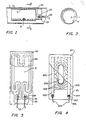
- FIGS. 1 and 2 show in section a part of a styling shaft 1 of a styling rod according to the invention. It is not shown that here the styling bar is provided with a handle and that the styling shaft 1 is connected at one end to the handle. But this is the usual design of a styling stick. In any case, hair to be styled can be wrapped around the styling shaft 1.
- the hairdressing shaft 1 is tubular and, in the exemplary embodiment shown and preferred here, is made of metal and is preferably thermally insulated from the handle.
- an electric heater is housed inside. This electric heater points a resistance heating element 2 housed in the hairdressing shaft 1 and shown in FIGS. 1 and 2.
- the resistance heating element 2 is provided with connections 24 for connecting lines 23, which lead to an electrical current source, for example a mains connection, but also an accumulator.
- an electrical current source for example a mains connection, but also an accumulator.
- the styling shaft 1 is made of metal, the resistance heating element 2 is provided with insulation to protect against contact with electrically conductive parts of the styling rod. However, this cannot be seen in FIGS. 1 and 2.
- the hairdressing shaft 1 can, however, also consist of non-metallic, in particular electrically insulating material, in which case a corresponding insulation on this side of the resistance heating element 2 is not necessary.
- the resistance heating element 2 is pressed with the aid of the spring element 3 designed as an adapter sleeve against the inner wall of the styling shaft 1, which can be seen particularly well from FIG. 2.
- the resistance heating element 2 can be designed as shown in FIG. 3 or as shown in FIG. 4, but can also be designed differently, provided that it is sufficiently electrically insulated in the areas in which metal parts are in contact or are to be feared. It is also essential that the resistance heating element 2 is sufficiently elastic and flexible to be able to fit closely against the inner wall of the styling shaft 1 of the styling rod, so that good heat transfer takes place. 1 shows that only the resistance areas of the resistance heating element 2 are clamped between the styling shaft 1 and the spring element 3, but that electrically conductive connection areas 26 of the resistance heating element 2 are not clamped.
- a resistance heating element 2 which comprises a support 21, here an approximately 1.3 mm thick Nomex paper (a paper consisting of heat-resistant polyamide fibers, Wz. Du Pont), and a heating resistor 22, here a thin metal foil, namely an approximately 0.25 mm thick nickel foil.
- the heating resistor 22 is punched out and glued to the carrier 21 and, in the exemplary embodiment shown here, guided in a loop shape such that there are six short parallel strips in the lower region in FIG. 3 and four short parallel strips in the upper region in FIG. 3, whereas only two parallel strips are present in the central region are available.
- the heating resistor 22 ends in two large integrated connection areas 26, in which two lines 23 are connected in an electrically conductive and mechanically fixed manner by means of ring-shaped connections 24 and eyelets 25.
- the eyelets 25 are driven both by the heating resistor 22 designed as nickel foil and by the carrier 21 designed as Nomex paper, so that the stronger Nomex paper prevents the lines 23 from pulling the heating resistor 22 when they are pulled.
- the resistance heating element 2 including the connections 24 has been electrically insulated with a thin insulating film 28.
- the insulating film 28 consists of an approximately 0.25 mm thick polyimide film. This is an electrically good insulating, heat-resistant and good heat-conducting material.
- the polyimide side that is to say the side of the resistance heating element 2 protected with the insulating film 28, faces the hairstyle shaft 1 in the hairdressing shaft 1 provided here, whereas the less thermally conductive Nomex paper side, that is to say the carrier 21, faces the spring element 3. In this way it is ensured that the heat generated is essentially transferred to the styling shaft 1.
- the Nomex paper side that is to say the carrier 21, is not electrically insulated on the side facing away from the heating resistor 22, at least not in the areas in which the eyelets 25 are arranged, the feature explained above is of importance that the spring element 3 is itself does not extend into the connection areas 26, since the spring element 3, consisting of metallic material, would otherwise short-circuit the connections 24.
- the resistance heating element 2 shown in FIG. 4 in a further embodiment consists of a carrier 201 made of heat-resistant, flexible and electrically insulating material, for example Nomex paper, impregnated glass fiber fabric, polyimide film, Teflon film.
- the carrier 201 is coated on its upper side with a heating resistor 202 of predetermined resistance.
- this coating forming the heating resistor 202 is a dispersion of carbon or graphite particles in a polymeric resin. The specific resistance is measured in ⁇ cm.
- two approximately parallel strips 203 of electrically conductive material are arranged on the carrier on the edge of the coating forming the essential part of the heating resistor 202.
- these are silver or nickel particles which are suspended in a thermosetting resin.
- the strips 203 extend further than the coating forming the heating resistor 202 and form two connection regions 204.
- Insulated lines 205 are electrically conductively connected on both connection regions 204, with the aid of connections 206.
- the coating which essentially forms the heating resistor 202 shows in its A free area 208 in the middle. This free area 208 can be formed, for example, by an elongated hole. It is only essential, however, that there is no coating forming the heating resistor 202 here.
- connection regions 204 and the strips 203 If a voltage is applied to the connection regions 204 and the strips 203, electrical current flows through the heating resistor 202 in the form of a coating, approximately along the current flow lines 209.
- the heat density which is generated by this current distribution in the heating resistor 202 corresponds to the current density, so that in more heat is generated in the end regions of the resistance heating element 2 than in the central region.
- An insulating film 210 which is heat-resistant, flexible and electrically insulating, covers the entire resistance heating element 2 including the connection regions 204, connections 206 and eyelets 207.
- the resistance heating element 503 generates heat uniformly over the entire heating area 502.
- the resistance heating element 603 is designed so that the heat generation is concentrated in the end regions of the heating region 602.
- the resulting temperature distributions in the styling shaft 1 are shown in the curves 504 and 604.
- the region “x” of the styling shaft 501 with temperatures above 150 ° C. is quite narrow in comparison with the region “y” of the styling shaft 601.
- Die Areas 505 and 605 under curves 504 and 604, which are proportional to the heat losses, however, are similar in size, so that it follows that with the resistance heating element 603, the heat output is implemented more efficiently.
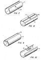
- FIG. 7, 8, 9 and 10 show four different exemplary embodiments of a spring element 3 for a styling stick according to the teaching of the invention.
- the exemplary embodiments differ in how the respective spring element 3, designed as an adapter sleeve, is pulled together for insertion into the styling shaft 1.
- a variety of other embodiments are conceivable.
- the spring element 3 designed as an adapter sleeve is provided in all cases near the edges of the longitudinal slot provided in all cases with engagement formations 32 or engagement openings 31 for an insertion tool, which is not shown, however.
- the engagement formations 32 are sometimes also flange-like areas in which the engagement openings 31 are then formed (FIGS. 8 and 10).
- the spring element 3 designed as an adapter sleeve can be reduced in diameter in the exemplary embodiments shown here for insertion into the hairdressing shaft 1, that is to say it can be contracted.
- the spring element 3 then springs back into its normal state after use in the styling shaft 1, as a result of which the resistance heating element 2 is pressed against the styling shaft 1 from the inside.
- the resistance heating element 2 can also be glued to the outside of the spring element 3 before it is inserted into the styling shaft 1.
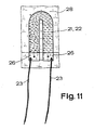
- Fig. 11 makes another, particularly preferred embodiment of the invention clear, which is characterized in that the carrier 21 consists of a paper or a paper-like material, in the preferred embodiment shown here and consists of a heat-resistant synthetic fiber fabric or synthetic fiber pressed body, in particular made of polyamide, and that the heating resistor 22 is designed as an impregnation of the carrier 21 consisting of fine carbon or graphite particles in a dispersion.
- This embodiment of the resistance heating element 2 according to the invention is particularly expedient in terms of production technology.
- the heating resistor 22 is in fact obtained here in its final form by cutting out the essentially U-shaped support 21, which can be seen in FIG. 11, from a large, fully impregnated support 21. So here carrier 21 and heating resistor 22 are fused into an inseparable unit. Nomex paper can also be used as the material here.
- connection regions 26 for connecting lines 23 deserve special attention.
- the connection areas 26 can, for example, as additional coatings made of electrically conductive material or as thin, applied metal foils pressed by external pressure on the corresponding areas of the heating resistor 22 or as folded in the corresponding areas around the heating resistor 22 and connected to both sides, in particular perforated and metal foils soldered from both sides. The latter is shown in Fig. 11. In any case, the lines 23 are then soldered, clamped or otherwise connected in an electrically conductive manner to the connection regions 26.
- the resistance heating element 2 consists of the flat, flexible heating resistor 22 and two insulating foils 28, which are connected on both sides to the heating resistor 22 and which can be configured in terms of material in the manner explained above.
Landscapes
- Resistance Heating (AREA)
- Hair Curling (AREA)
Applications Claiming Priority (2)
| Application Number | Priority Date | Filing Date | Title |
|---|---|---|---|
| US781790 | 1985-09-30 | ||
| US06/781,790 US4697066A (en) | 1985-09-30 | 1985-09-30 | Electric hair curling waved with improved heating element arrangement |
Publications (2)
| Publication Number | Publication Date |
|---|---|
| EP0218797A2 true EP0218797A2 (fr) | 1987-04-22 |
| EP0218797A3 EP0218797A3 (fr) | 1988-07-20 |
Family
ID=25123950
Family Applications (1)
| Application Number | Title | Priority Date | Filing Date |
|---|---|---|---|
| EP86108834A Withdrawn EP0218797A3 (fr) | 1985-09-30 | 1986-06-30 | Fer à friser à chauffage électrique |
Country Status (2)
| Country | Link |
|---|---|
| US (1) | US4697066A (fr) |
| EP (1) | EP0218797A3 (fr) |
Cited By (4)
| Publication number | Priority date | Publication date | Assignee | Title |
|---|---|---|---|---|
| EP0401441A1 (fr) * | 1987-12-01 | 1990-12-12 | Giovanni Management Canada Ltd. | Fer ou brosse à onduler électrique à batteries |
| DE202006000670U1 (de) * | 2006-01-18 | 2007-05-31 | Wik Far East Ltd. | Widerstandsheizelement für ein Haarformgerät sowie damit ausgerüstetes Haarformgerät |
| DE102012201739A1 (de) * | 2012-02-06 | 2013-08-08 | BSH Bosch und Siemens Hausgeräte GmbH | Elektrischer Haarglätter |
| WO2023161601A1 (fr) * | 2022-02-24 | 2023-08-31 | Dyson Technology Limited | Appareil de soins capillaires |
Families Citing this family (11)
| Publication number | Priority date | Publication date | Assignee | Title |
|---|---|---|---|---|
| JPS62167503A (ja) * | 1986-01-20 | 1987-07-23 | 松下電工株式会社 | ヘア−カ−ル器 |
| USD314444S (en) | 1988-06-07 | 1991-02-05 | Windmere Corporation | Hair curler or similar article |
| US5354967A (en) * | 1992-11-13 | 1994-10-11 | Helen Of Troy Corporation | Hair styling appliance heater and control |
| KR20040029920A (ko) * | 2002-10-04 | 2004-04-08 | 홍성태 | 헤어 롯드 및 그 제조방법 |
| WO2004064566A2 (fr) * | 2003-01-16 | 2004-08-05 | Conair Corporation | Bigoudi pourvu d'un revetement ceramique |
| WO2006101498A1 (fr) * | 2005-03-18 | 2006-09-28 | Powerpulse Technologies, L.P. | Element chauffant cutane |
| FR2927233B1 (fr) * | 2008-02-08 | 2011-11-11 | Oreal | Dispositif pour l'application d'un produit cosmetique, comportant un organe chauffant |
| DE102009011685A1 (de) * | 2009-03-04 | 2010-09-09 | Andreas Stihl Ag & Co. Kg | Handgeführtes Arbeitsgerät |
| SG2013057377A (en) * | 2013-07-26 | 2015-02-27 | Tai Wah Distributors Pte Ltd | Hair appliances heating mat |
| JP6347651B2 (ja) * | 2014-04-10 | 2018-06-27 | 日本電産サンキョー株式会社 | ダンパ装置およびヒータ |
| GB2634278A (en) * | 2023-10-04 | 2025-04-09 | Jemella Ltd | Heater apparatus and method |
Family Cites Families (14)
| Publication number | Priority date | Publication date | Assignee | Title |
|---|---|---|---|---|
| GB119094A (en) * | 1917-09-20 | 1918-09-20 | William Netherton | Improvements in or relating to Hair-dressing Appliances. |
| US1336559A (en) * | 1918-08-07 | 1920-04-13 | Gutzwiller Herbert | Electric internal tube-heater |
| US1358219A (en) * | 1920-01-09 | 1920-11-09 | Edgar T Lancaster | Power plant |
| US1477602A (en) * | 1921-04-25 | 1923-12-18 | Simon Maurice | Electrical heating unit |
| US1555953A (en) * | 1921-04-25 | 1925-10-06 | Simon Maurice | Electrical heating unit and method of making same |
| US1674488A (en) * | 1922-12-20 | 1928-06-19 | Gen Electric | Electric heating unit |
| US2371696A (en) * | 1943-07-17 | 1945-03-20 | Cities Service Oil Co | Helical electric immersion heater |
| US2501417A (en) * | 1946-08-15 | 1950-03-21 | Smits Wytze Beye | Electrical tube-immersion heater |
| US2473183A (en) * | 1947-07-16 | 1949-06-14 | Bates Mfg Co | Electrically conductive fabric |
| US3129314A (en) * | 1960-08-01 | 1964-04-14 | Babcock & Wilcox Co | Electric heater |
| GB1040871A (en) * | 1964-05-04 | 1966-09-01 | Midland Silicones Ltd | Method of making electrical connections |
| FR1553082A (fr) * | 1967-11-29 | 1969-01-10 | ||
| DE2840360A1 (de) * | 1978-09-16 | 1980-04-03 | Braun Ag | Lockenstab mit einem wickelkoerper |
| JPS5824124B2 (ja) * | 1978-10-05 | 1983-05-19 | 松下電器産業株式会社 | 頭髪調整具 |
-
1985
- 1985-09-30 US US06/781,790 patent/US4697066A/en not_active Expired - Fee Related
-
1986
- 1986-06-30 EP EP86108834A patent/EP0218797A3/fr not_active Withdrawn
Cited By (6)
| Publication number | Priority date | Publication date | Assignee | Title |
|---|---|---|---|---|
| EP0401441A1 (fr) * | 1987-12-01 | 1990-12-12 | Giovanni Management Canada Ltd. | Fer ou brosse à onduler électrique à batteries |
| DE202006000670U1 (de) * | 2006-01-18 | 2007-05-31 | Wik Far East Ltd. | Widerstandsheizelement für ein Haarformgerät sowie damit ausgerüstetes Haarformgerät |
| WO2007082903A1 (fr) * | 2006-01-18 | 2007-07-26 | Wik Far East Ltd. | Élément de chauffage résistif pour un appareil de coiffure et appareil de coiffure ainsi équipé |
| DE102012201739A1 (de) * | 2012-02-06 | 2013-08-08 | BSH Bosch und Siemens Hausgeräte GmbH | Elektrischer Haarglätter |
| EP2622986A3 (fr) * | 2012-02-06 | 2015-12-30 | BSH Hausgeräte GmbH | Lisseur capillaire électrique |
| WO2023161601A1 (fr) * | 2022-02-24 | 2023-08-31 | Dyson Technology Limited | Appareil de soins capillaires |
Also Published As
| Publication number | Publication date |
|---|---|
| EP0218797A3 (fr) | 1988-07-20 |
| US4697066A (en) | 1987-09-29 |
Similar Documents
| Publication | Publication Date | Title |
|---|---|---|
| EP0218797A2 (fr) | Fer à friser à chauffage électrique | |
| EP0350528B1 (fr) | Radiateur | |
| DE2614433C3 (de) | Selbstregelndes Heizelement | |
| DE68913666T2 (de) | Selbstregulierendes Heizelement mit wärmeleitenden Verlängerungen. | |
| DE3433196A1 (de) | Ptc-widerstandsvorrichtung | |
| EP0333906B1 (fr) | Résistance chauffante à coefficient de température positif | |
| DE69010458T2 (de) | Heizbänder. | |
| DE2837316A1 (de) | Haartrockner und verfahren zum herstellen eines heizkoerpers fuer diesen haartrockner | |
| DE2823059A1 (de) | Temperaturfuehlvorrichtung, insbesondere fuer geraete zur erwaermung oder erhitzung von nahrungsmitteln | |
| DE2946842A1 (de) | Aus einem wabenfoermigen koerper bestehendes heizleiterelement aus kaltleitermaterial | |
| DE3102849C2 (fr) | ||
| DE2709413B2 (fr) | ||
| DE3023644C2 (de) | Gehäuse für einen elektrischen keramischen Kaltleiter zum Verdampfen von chemischen Desinfektions- und/oder Insektizidsubstanzen | |
| EP2622986B1 (fr) | Lisseur capillaire électrique | |
| DE20108963U1 (de) | Elektrischer Flachheizkörper | |
| DE2515897C3 (de) | Biegsames elektrisches Flächenheizelement | |
| DE2907763A1 (de) | Zeitschalter zum verzoegerten ein- und ausschalten von elektrischen geraeten | |
| DE1640197B2 (de) | Bimetallschalter | |
| DE3425208A1 (de) | Heizanordnung fuer elektrische waermegeraete mit ptc-heizelementen | |
| DE3232404C2 (de) | Keramischer Kaltleiter mit Metallbelägen und daran durch Klemmkontakt angeschlossenen Stromzuführungen | |
| DE9407104U1 (de) | Heizvorrichtung | |
| DE69032705T2 (de) | Heizelement | |
| AT207930B (de) | Heizelement zur Beheizung des Bimetalles bei thermischen Schaltvorrichtungen mit Bimetallauslösung | |
| DE3204273C2 (de) | Kontaktelement zur Zwischenlage zwischen wärmeleitende Teile eines Gerätes, insbesondere eines Gehäuses für eine elektrische Baugruppe | |
| DE3935054C2 (fr) |
Legal Events
| Date | Code | Title | Description |
|---|---|---|---|
| PUAI | Public reference made under article 153(3) epc to a published international application that has entered the european phase |
Free format text: ORIGINAL CODE: 0009012 |
|
| 17P | Request for examination filed |
Effective date: 19870105 |
|
| AK | Designated contracting states |
Kind code of ref document: A2 Designated state(s): AT BE CH DE FR GB IT LI LU NL SE |
|
| PUAL | Search report despatched |
Free format text: ORIGINAL CODE: 0009013 |
|
| STAA | Information on the status of an ep patent application or granted ep patent |
Free format text: STATUS: THE APPLICATION HAS BEEN WITHDRAWN |
|
| AK | Designated contracting states |
Kind code of ref document: A3 Designated state(s): AT BE CH DE FR GB IT LI LU NL SE |
|
| 18W | Application withdrawn |
Withdrawal date: 19880620 |