EP0218957A2 - Dispositif de surveillance de la respiration et du fonctionnement cardiaque - Google Patents
Dispositif de surveillance de la respiration et du fonctionnement cardiaque Download PDFInfo
- Publication number
- EP0218957A2 EP0218957A2 EP86113101A EP86113101A EP0218957A2 EP 0218957 A2 EP0218957 A2 EP 0218957A2 EP 86113101 A EP86113101 A EP 86113101A EP 86113101 A EP86113101 A EP 86113101A EP 0218957 A2 EP0218957 A2 EP 0218957A2
- Authority
- EP
- European Patent Office
- Prior art keywords
- bed
- sensor
- aligned
- sensors
- bearing
- Prior art date
- Legal status (The legal status is an assumption and is not a legal conclusion. Google has not performed a legal analysis and makes no representation as to the accuracy of the status listed.)
- Granted
Links
- 230000029058 respiratory gaseous exchange Effects 0.000 title claims abstract description 13
- 238000012544 monitoring process Methods 0.000 title claims abstract description 9
- 230000004217 heart function Effects 0.000 title 1
- 230000000694 effects Effects 0.000 claims abstract description 14
- 230000000747 cardiac effect Effects 0.000 claims abstract description 13
- 230000005484 gravity Effects 0.000 claims description 20
- 230000009471 action Effects 0.000 claims description 6
- 239000000725 suspension Substances 0.000 claims description 6
- 230000006835 compression Effects 0.000 claims description 3
- 238000007906 compression Methods 0.000 claims description 3
- 230000035515 penetration Effects 0.000 claims description 3
- 230000000284 resting effect Effects 0.000 claims description 3
- 230000000241 respiratory effect Effects 0.000 abstract description 10
- 238000005188 flotation Methods 0.000 abstract 1
- 238000000034 method Methods 0.000 description 5
- 230000001960 triggered effect Effects 0.000 description 4
- 230000008901 benefit Effects 0.000 description 3
- 238000006243 chemical reaction Methods 0.000 description 3
- 238000010586 diagram Methods 0.000 description 3
- 230000008569 process Effects 0.000 description 3
- 239000008280 blood Substances 0.000 description 2
- 210000004369 blood Anatomy 0.000 description 2
- 230000001419 dependent effect Effects 0.000 description 2
- 230000004069 differentiation Effects 0.000 description 2
- 238000011156 evaluation Methods 0.000 description 2
- 238000005259 measurement Methods 0.000 description 2
- 238000012986 modification Methods 0.000 description 2
- 230000004048 modification Effects 0.000 description 2
- 230000000474 nursing effect Effects 0.000 description 2
- 230000006641 stabilisation Effects 0.000 description 2
- 238000011105 stabilization Methods 0.000 description 2
- 206010038669 Respiratory arrest Diseases 0.000 description 1
- 230000003187 abdominal effect Effects 0.000 description 1
- 210000002376 aorta thoracic Anatomy 0.000 description 1
- 238000000418 atomic force spectrum Methods 0.000 description 1
- 239000003990 capacitor Substances 0.000 description 1
- 238000011835 investigation Methods 0.000 description 1
- 239000007788 liquid Substances 0.000 description 1
- 239000000463 material Substances 0.000 description 1
- 238000010606 normalization Methods 0.000 description 1
- 238000012545 processing Methods 0.000 description 1
- 210000001147 pulmonary artery Anatomy 0.000 description 1
- 230000000087 stabilizing effect Effects 0.000 description 1
- 230000003068 static effect Effects 0.000 description 1
Images


Classifications
-
- A—HUMAN NECESSITIES
- A61—MEDICAL OR VETERINARY SCIENCE; HYGIENE
- A61B—DIAGNOSIS; SURGERY; IDENTIFICATION
- A61B5/00—Measuring for diagnostic purposes; Identification of persons
- A61B5/103—Measuring devices for testing the shape, pattern, colour, size or movement of the body or parts thereof, for diagnostic purposes
- A61B5/11—Measuring movement of the entire body or parts thereof, e.g. head or hand tremor or mobility of a limb
- A61B5/113—Measuring movement of the entire body or parts thereof, e.g. head or hand tremor or mobility of a limb occurring during breathing
-
- A—HUMAN NECESSITIES
- A61—MEDICAL OR VETERINARY SCIENCE; HYGIENE
- A61B—DIAGNOSIS; SURGERY; IDENTIFICATION
- A61B5/00—Measuring for diagnostic purposes; Identification of persons
- A61B5/103—Measuring devices for testing the shape, pattern, colour, size or movement of the body or parts thereof, for diagnostic purposes
- A61B5/11—Measuring movement of the entire body or parts thereof, e.g. head or hand tremor or mobility of a limb
- A61B5/1102—Ballistocardiography
-
- A—HUMAN NECESSITIES
- A61—MEDICAL OR VETERINARY SCIENCE; HYGIENE
- A61B—DIAGNOSIS; SURGERY; IDENTIFICATION
- A61B2503/00—Evaluating a particular growth phase or type of persons or animals
- A61B2503/04—Babies, e.g. for SIDS detection
-
- A—HUMAN NECESSITIES
- A61—MEDICAL OR VETERINARY SCIENCE; HYGIENE
- A61B—DIAGNOSIS; SURGERY; IDENTIFICATION
- A61B5/00—Measuring for diagnostic purposes; Identification of persons
- A61B5/68—Arrangements of detecting, measuring or recording means, e.g. sensors, in relation to patient
- A61B5/6887—Arrangements of detecting, measuring or recording means, e.g. sensors, in relation to patient mounted on external non-worn devices, e.g. non-medical devices
- A61B5/6889—Rooms
-
- A—HUMAN NECESSITIES
- A61—MEDICAL OR VETERINARY SCIENCE; HYGIENE
- A61B—DIAGNOSIS; SURGERY; IDENTIFICATION
- A61B5/00—Measuring for diagnostic purposes; Identification of persons
- A61B5/68—Arrangements of detecting, measuring or recording means, e.g. sensors, in relation to patient
- A61B5/6887—Arrangements of detecting, measuring or recording means, e.g. sensors, in relation to patient mounted on external non-worn devices, e.g. non-medical devices
- A61B5/6891—Furniture
Definitions
- This type of monitoring is of considerable importance not only in the guard station of a clinic, but also in the newborn ward, because in this way signs of respiratory arrest can be immediately recognized by appropriate signal processing, so that the necessary countermeasures can be initiated.
- the advantage of this method is that it is possible to monitor breathing activity without having to take any measurements on the patient or newborn himself. However, further monitoring options are neither envisaged nor possible on this basis.
- the invention is based on the task to arrive at a more detailed statement of the respiratory and cardiac activity than is possible with the known device. It should therefore at least be running alongside a statement about breathing activity activity based on reliably usable signals.
- the information options are also to be expanded in the direction of further differentiated monitoring of both breathing and cardiac activity.
- breathing additional information about the type of breathing (abdominal or chest breathing) and the breathing pressure are of interest, while for cardiac activity the direction of the blood output deserves special attention, especially in newborns. Ejecting blood into a still open Botalli duct would result in a characteristic impulse that forms an angle of less than 90 ° to connect the pulmonary artery to the descending aorta. Different impulse components would accordingly result in the back or prone position and in the left or right side position.
- impulses are in the general sense short-term effects of mechanical quantities or their short-term deviation from a basic value. Therefore, one not only comes to a direction-dependent statement about the mass shifts when breathing, but also about the associated reaction force curves during inhalation and exhalation.
- the bed Since the bed is not only movably supported on all sides, but is also subject to a restoring force, the extent to which changes in the bed's position actually occur is less important. However, there is at least one sensor which responds in the horizontal direction and one which responds in the vertical direction for the investigation of the processes to be detected, so that there are at least two components which can be used as a basis for the evaluation.
- a further differentiation of the evaluation is given in that, deviating from the prior art, the signals triggered by cardiac activity are no longer filtered out, but are subject to simultaneous monitoring. In this respect, the signal frequency and signal form have a differentiating meaning, since they allow the impulses from respiratory activity and cardiac activity to be separated from one another.
- At least two pulse components are registered, one of which is aligned in a horizontal plane and the second is aligned vertically. It is particularly expedient to align two sensors in the horizontal plane, which in turn are at right angles to one another. Correspondingly detected pulse components, together with their frequency-related differentiation, have a far-reaching meaningfulness in the direction of direction-dependent impulses of respiratory and cardiac activity.
- the device according to the invention can be carried out in different ways.
- a suspension above the center of gravity of the bed or a support of the same below its center of gravity can be considered, the restoring moment being given in the first case in the event of positional deviations due to the shift in the center of gravity, whereas in the second case so-called unstable bearing is additional Means are provided which bring about a provision.
- additional means which can work without contact, can be provided, for example, with the same polarity of the magnets at the bed and at a stationary remote station
- a suspension above the center of gravity of the bed is expediently carried out in such a way that the vertically oriented sensor is arranged in the direction of action of the center of gravity, and that with horizontal spacing of this direction of action, the other sensor or sensors with the suspension or with the bed upon deflection of the latter its normal position interact.
- the bed can also be gimbaled, in which case the vertically oriented sensor is used to support one of the bearing axes, while the other sensor or sensors are aligned with edges of the bed or frame parts.
- the latter arrangement has the advantage that the bed remains freely accessible from above.
- a similar advantage can also be achieved in the case of storage below the center of gravity of the bed, in that a base-side support column of the bed passes through a bearing ball which can be moved on supporting balls.
- the support column is expediently provided with a counterweight after passing through the bearing ball.
- the vertically aligned sensor can be arranged directly in the support column between the bearing ball and the bed, whereas the other sensors can be provided on the support column, provided that e.g. are elements of a Hall generator, capacitor or radiation-reflecting or radiation-generating means. Fixed to the latter sensors, for example, receivers are then arranged, which show the extent of a deflection.
- the vertically oriented sensor In the case of a floating bearing or a similarly acting bearing by means of a spiral compression spring supporting the bed, the vertically oriented sensor consists in supporting a horizontal edge of the bed, whereas the further sensors are aligned on a vertical edge of the bed.
- the normal position is stabilized by providing in particular the magnetic poles already mentioned and corresponding, rectified poles of stationary magnets corresponding to them.
- the bed can be stored in a particularly space-saving and effective manner by means of a spherical cap which is curved downwards and in which there is a massive weight body which is so massive. its center of gravity is sufficiently shifted downwards to always generate a restoring force.
- the vertically aligned sensor must be provided near the bearing point of the spherical cap on the stationary base and must be aligned with the bearing point.
- the remaining sensors can be aligned to the edges of the bed.
- the sufficiently heavy mass within the spherical cap is easy to achieve, so that the desired shift in the center of gravity of the entire system results.
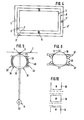
- the bed 1 is suspended above its center of gravity 3 by means of belts 25 on the hook 26 of a rigid wall arm 27.
- the vertically oriented sensor 5 is included in this suspension so that it lies in the direction of action 4 of the center of gravity 3 of the bed 1. The forces exerted in the vertical direction are thus detected.
- the right side wall of the bed 1 is supported on a stationary wall by means of an intermediate member, the further, horizontally oriented sensor 2 being included in this support.
- the further, horizontally oriented sensor 2 being included in this support.
- a further sensor 2 ′ shown in dashed lines, which allows the forces directed at an angle of 90 ° to align the sensor 2 to be absorbed.
- the arrangement according to FIG. 1 thus realizes the essence of the invention in that, on the one hand, the vertical component and, on the other hand, two horizontal components perpendicular to one another are detected by pulses which result from the heart and respiratory reactions of a person in bed 1.
- the embodiment according to FIG. 2 uses a support frame 24 instead of straps, in which a frame arm 28 stands up to the middle of the bed is cranked out, so that there is a bearing tip 29, via which the support frame 24 with the bed on the projecting wall arm 27 at the bearing point 30 is supported.
- the vertically aligned sensor 5 is integrated into the bearing tip 29.
- the wall arm 27 is formed with a cutout 31, in the wall of which there are further, horizontally oriented sensors 2, 2 ', which are oriented at an angle of 90 ° to the frame arm 28 and correspondingly one from there possible reflection of sensor beams Determine deflections of the frame arm 28 from its normal position, for example by directing the reflected sensor beam onto photo diode line cameras.
- FIG. 3 also shows the bearing point 30 which is designed from the point of view of stable storage.
- the poles of stationary magnets 19 can also be seen, which are aligned with one another in such a way that the frame arm 28 is stabilized in its normal position an additional stabilizing force is effective.
- the gimbal shown in Figure 4 provides two mutually perpendicular bearing axes 6 and 6 ', of which the bearing axis 6 of the bed 1 is mounted directly in the frame 8, which in turn is mounted in a fixed frame 8' by means of the bearing 6 '.
- Below the axis of the bearing 6 ' is the sensor 5 aligned in the vertical direction, whereas two further sensors 2, 2' aligned horizontally on the edges 7 detect deflections of the frame 8 on the one hand and deflections of the bed 1 on the other.
- the bed 1 is supported by means of a support column 9 which passes through a bearing ball 10 in the penetration points 11 and 12.
- the bearing ball 10 is supported in a ball cage 40 with supporting balls, the outer ball shell 32 of which is held by a support shell 33 which is provided with a circumferential seal 34 opposite the bearing ball 10.
- the lower part of the support column 9 carries a counterweight 14 which is arranged such that it stabilizes the normal position of the bed 1, the frictional resistance between the bearing ball 10 is easily overcome.
- the vertically oriented sensor 5 is located between the upper penetration point 11 of the support column 9 through the bearing ball 10 and the bottom of the bed 1.
- the counterweight 14 carries a reflector 42 on the sensor beams of a light source, not shown in the drawing, so that deflections of the bed 1 can be detected by horizontally aligned sensors.
- a reflector 42 on the sensor beams of a light source, not shown in the drawing, so that deflections of the bed 1 can be detected by horizontally aligned sensors.
- only an upper and a lower ball ring 36 are used, which ball rings are fastened in the holder 37.
- the bearing according to FIGS. 5 and 6 thus acts like a pendulum, which compensates for the movements of the bed from its normal position. The stabilization of the bearings due to the center of gravity permits a combination of this type of bearing with that according to FIG. 1.
- the floating bearing according to FIG. 7 provides for the arrangement of the bed 1 in an outer shell 35 which, for example, holds a liquid 16.
- the bottom of the bed 1 also carries a seal.
- the frame of the bed 1 is kept at a distance from the shell 12, for which purpose the supports 15 serve.
- These are shown only schematically in FIGS. 7 and 8. They can be realized magnetically, similarly to the diagram in FIG. 3, in that in particular magnetic poles 18 according to FIG. 10 are arranged on the bed, while stationary magnets 19 are arranged in the same direction, so that their poles try to keep the poles 18 at a distance.
- vertically aligned sensors 5 can be fitted between the bottom of the bed 1 and the bearing shell, whereas horizontally aligned sensors 2, 2 'are arranged such that they point to the vertical edges 17 of the bed 1 and accordingly Can record changes in location.
- FIG. 9 A similar arrangement is obtained according to FIG. 9, in which case the bed 1 is arranged on a spiral compression spring 41.
- the vertically aligned sensor 5 and the two horizontally aligned sensors 2 and 2 ' can again be seen.
- the bed 1 is arranged on a spherical cap 20, with the bed 1 and the mentioned spherical cap is a weight body 21, so that there is a center of gravity 22 between bed 1 and weight body 21, which stabilizes the bed in its normal position.
- the weight of the spherical cap 20 is also taken into account, so that the latter is expediently made from a heavy material.
- the spherical cap 20 is supported in the bearing point 23 either on the horizontal base 38 or on an oppositely curved bearing element 39.
- the vertically oriented sensor 5, not shown here is provided, for the alignment of which the line of action of the common center of gravity 22 is decisive.
- An arrangement of the weight body can also be made according to size and location from the point of view that the natural vibration frequency of the overall arrangement is changed. In this way it is possible to avoid disruptive vibrations of the overall arrangement by occurring at a frequency which does not result in any falsification of the respiratory or cardiac signals to be measured. In this respect, an arrangement of the weight body 21 improves the availability of reliably usable signals.
- the sensor or sensors as was known from the prior art on which they are based, emit their signals to circuit elements, on the basis of which, when the signals fail to appear, an alarm device is activated which enables the nursing staff to take immediate countermeasures, for example when the breath stops.
- the present invention additionally uses the alarm triggering secondary signal to operate an automatic wake-up device.
- the above-mentioned secondary signal is used to switch on a drive that sets the bed in motion, so that small children in particular are woken up and start to breathe normally again.
- the arrangement can also be made so that only a single movement of the bed is triggered by the drive. In this case, the signals then emitted are no longer disturbed by the function of the drive.
- a signal 43 leads from the sensor 2 to an amplifier and signal converter 44.
- This component shown here only as a block diagram, is known as such according to the prior art. If the signal 43 is absent for a predetermined time, it generates a secondary signal 45. This secondary signal triggers an alarm device 49 according to the known prior art.
- a connection of the secondary signal 45 to a drive 46 that is to say, for example, to an electric motor, also runs in parallel, so that when a signal 45 is present, this drive is switched on.
- the drive is designed such that a plunger 47 can extend in the direction of arrow 48 when the drive is switched on. The plunger 47 presses in front of the component belonging to the hook 26, suspended on the wall arm 27, so that the bed 1 starts to move. This movement may already be sufficient to trigger a wake-up process and to remedy the temporary cessation of breath.
Landscapes
- Health & Medical Sciences (AREA)
- Life Sciences & Earth Sciences (AREA)
- Heart & Thoracic Surgery (AREA)
- Surgery (AREA)
- Physics & Mathematics (AREA)
- Dentistry (AREA)
- Biophysics (AREA)
- Pathology (AREA)
- Engineering & Computer Science (AREA)
- Biomedical Technology (AREA)
- Physiology (AREA)
- Medical Informatics (AREA)
- Molecular Biology (AREA)
- Oral & Maxillofacial Surgery (AREA)
- Animal Behavior & Ethology (AREA)
- General Health & Medical Sciences (AREA)
- Public Health (AREA)
- Veterinary Medicine (AREA)
- Cardiology (AREA)
- Measuring And Recording Apparatus For Diagnosis (AREA)
- Measurement Of The Respiration, Hearing Ability, Form, And Blood Characteristics Of Living Organisms (AREA)
- Invalid Beds And Related Equipment (AREA)
- Electrotherapy Devices (AREA)
Priority Applications (1)
| Application Number | Priority Date | Filing Date | Title |
|---|---|---|---|
| AT86113101T ATE77039T1 (de) | 1985-10-12 | 1986-09-24 | Vorrichtung zur ueberwachung der atmung und herztaetigkeit. |
Applications Claiming Priority (2)
| Application Number | Priority Date | Filing Date | Title |
|---|---|---|---|
| DE19853536491 DE3536491A1 (de) | 1985-10-12 | 1985-10-12 | Vorrichtung zur ueberwachung der atmung und herztaetigkeit |
| DE3536491 | 1985-10-12 |
Publications (3)
| Publication Number | Publication Date |
|---|---|
| EP0218957A2 true EP0218957A2 (fr) | 1987-04-22 |
| EP0218957A3 EP0218957A3 (en) | 1988-03-16 |
| EP0218957B1 EP0218957B1 (fr) | 1992-06-10 |
Family
ID=6283467
Family Applications (1)
| Application Number | Title | Priority Date | Filing Date |
|---|---|---|---|
| EP86113101A Expired - Lifetime EP0218957B1 (fr) | 1985-10-12 | 1986-09-24 | Dispositif de surveillance de la respiration et du fonctionnement cardiaque |
Country Status (5)
| Country | Link |
|---|---|
| US (1) | US4884578A (fr) |
| EP (1) | EP0218957B1 (fr) |
| JP (1) | JPH0741035B2 (fr) |
| AT (1) | ATE77039T1 (fr) |
| DE (2) | DE3536491A1 (fr) |
Cited By (2)
| Publication number | Priority date | Publication date | Assignee | Title |
|---|---|---|---|---|
| WO1999017658A1 (fr) * | 1997-10-03 | 1999-04-15 | Eth Transfer | Procede pour mesurer au moins le rythme respiratoire d'un etre vivant |
| US12123764B2 (en) | 2019-02-12 | 2024-10-22 | Sleep Number Corporation | System for adjusting the firmness of a substrate |
Families Citing this family (25)
| Publication number | Priority date | Publication date | Assignee | Title |
|---|---|---|---|---|
| IL86759A (en) * | 1988-06-16 | 1992-09-06 | Dror Nedivi | Medical monitoring system |
| US5107855A (en) * | 1990-03-08 | 1992-04-28 | Rkr Corporation | Apena monitor for detection of aperiodic sinusoidal movement |
| WO1991019456A1 (fr) * | 1990-06-14 | 1991-12-26 | Lesbar Pty Limited | Dispositif de surveillance respiratoire |
| IL119721A (en) * | 1996-11-29 | 2005-08-31 | Mindlife Ltd | Method and system for monitoring the physiological condition of a patient |
| US6280392B1 (en) * | 1998-07-29 | 2001-08-28 | Denso Corporation | Infant condition monitoring system and method using load cell sensor sheet |
| JP2003529433A (ja) * | 2000-04-07 | 2003-10-07 | レモ・イーエイチエフ | 呼吸運動の測定および装置 |
| JP4577740B2 (ja) * | 2000-08-18 | 2010-11-10 | Necトーキン株式会社 | 圧電式発光装置 |
| US6805673B2 (en) | 2002-02-22 | 2004-10-19 | Datex-Ohmeda, Inc. | Monitoring mayer wave effects based on a photoplethysmographic signal |
| US6709402B2 (en) | 2002-02-22 | 2004-03-23 | Datex-Ohmeda, Inc. | Apparatus and method for monitoring respiration with a pulse oximeter |
| US6896661B2 (en) * | 2002-02-22 | 2005-05-24 | Datex-Ohmeda, Inc. | Monitoring physiological parameters based on variations in a photoplethysmographic baseline signal |
| US6702752B2 (en) | 2002-02-22 | 2004-03-09 | Datex-Ohmeda, Inc. | Monitoring respiration based on plethysmographic heart rate signal |
| WO2003071938A1 (fr) * | 2002-02-22 | 2003-09-04 | Datex-Ohmeda, Inc. | Surveillance de parametres physiologiques basee sur des variations dans un signal de photoplethysmographie |
| GB0318935D0 (en) * | 2003-08-13 | 2003-09-17 | Mossanen Shams Iden | Pulmonary evaluation device |
| US8116839B1 (en) | 2005-02-25 | 2012-02-14 | General Electric Company | System for detecting potential probe malfunction conditions in a pulse oximeter |
| US7403806B2 (en) | 2005-06-28 | 2008-07-22 | General Electric Company | System for prefiltering a plethysmographic signal |
| US20100170043A1 (en) * | 2009-01-06 | 2010-07-08 | Bam Labs, Inc. | Apparatus for monitoring vital signs |
| US20080077020A1 (en) | 2006-09-22 | 2008-03-27 | Bam Labs, Inc. | Method and apparatus for monitoring vital signs remotely |
| US8444558B2 (en) * | 2009-01-07 | 2013-05-21 | Bam Labs, Inc. | Apparatus for monitoring vital signs having fluid bladder beneath padding |
| US8287452B2 (en) * | 2009-01-07 | 2012-10-16 | Bam Labs, Inc. | Apparatus for monitoring vital signs of an emergency victim |
| JP2012527290A (ja) | 2009-05-18 | 2012-11-08 | コーニンクレッカ フィリップス エレクトロニクス エヌ ヴィ | 心拍測定装置 |
| US8672853B2 (en) | 2010-06-15 | 2014-03-18 | Bam Labs, Inc. | Pressure sensor for monitoring a subject and pressure sensor with inflatable bladder |
| US11284808B2 (en) * | 2014-10-11 | 2022-03-29 | Linet Spol. S.R.O. | Device and method for measurement of vital functions, including intracranial pressure, and system and method for collecting data |
| US10542961B2 (en) | 2015-06-15 | 2020-01-28 | The Research Foundation For The State University Of New York | System and method for infrasonic cardiac monitoring |
| US11033195B2 (en) | 2015-11-10 | 2021-06-15 | United Arab Emirates University | Piezoelectric related apparatus and method for extracting cardiac cycle features from respiration signals |
| CN112914868B (zh) * | 2021-01-21 | 2022-03-01 | 四川大学华西第二医院 | 一种防呼吸暂停的新生儿鸟巢及使用方法 |
Family Cites Families (6)
| Publication number | Priority date | Publication date | Assignee | Title |
|---|---|---|---|---|
| US3076452A (en) * | 1961-03-09 | 1963-02-05 | Astro Space Lab Inc | Diagnostic aid |
| CH410274A (de) * | 1962-12-14 | 1966-03-31 | Astro Space Lab Inc | Bewegungsanalysator |
| US3547106A (en) * | 1968-01-08 | 1970-12-15 | American Electronic Lab | Activity detecting means |
| US3890958A (en) * | 1974-04-08 | 1975-06-24 | Moog Automotive Inc | Physiological diagnostic apparatus |
| US4619270A (en) * | 1984-04-16 | 1986-10-28 | Margolis Frederick J | Infant respiratory arrest stimulator device |
| US4681098A (en) * | 1985-10-11 | 1987-07-21 | Lee Arnold St J | System, apparatus and method for gathering physiological data |
-
1985
- 1985-10-12 DE DE19853536491 patent/DE3536491A1/de not_active Withdrawn
-
1986
- 1986-09-24 EP EP86113101A patent/EP0218957B1/fr not_active Expired - Lifetime
- 1986-09-24 DE DE8686113101T patent/DE3685627D1/de not_active Expired - Lifetime
- 1986-09-24 AT AT86113101T patent/ATE77039T1/de not_active IP Right Cessation
- 1986-10-13 JP JP61241572A patent/JPH0741035B2/ja not_active Expired - Lifetime
-
1988
- 1988-08-10 US US07/230,690 patent/US4884578A/en not_active Expired - Lifetime
Non-Patent Citations (1)
| Title |
|---|
| H. U. THAL: "Ober eine indirekte Methode zur kontinuierlichen Atmungsregistrierung", DISSERTATION, 1973 |
Cited By (3)
| Publication number | Priority date | Publication date | Assignee | Title |
|---|---|---|---|---|
| WO1999017658A1 (fr) * | 1997-10-03 | 1999-04-15 | Eth Transfer | Procede pour mesurer au moins le rythme respiratoire d'un etre vivant |
| US12123764B2 (en) | 2019-02-12 | 2024-10-22 | Sleep Number Corporation | System for adjusting the firmness of a substrate |
| US12123763B2 (en) | 2019-02-12 | 2024-10-22 | Sleep Number Corporation | Load sensor assembly for bed leg and bed with load sensor assembly |
Also Published As
| Publication number | Publication date |
|---|---|
| ATE77039T1 (de) | 1992-06-15 |
| DE3685627D1 (de) | 1992-07-16 |
| JPH0741035B2 (ja) | 1995-05-10 |
| EP0218957B1 (fr) | 1992-06-10 |
| JPS6287125A (ja) | 1987-04-21 |
| US4884578A (en) | 1989-12-05 |
| DE3536491A1 (de) | 1987-04-16 |
| EP0218957A3 (en) | 1988-03-16 |
Similar Documents
| Publication | Publication Date | Title |
|---|---|---|
| EP0218957B1 (fr) | Dispositif de surveillance de la respiration et du fonctionnement cardiaque | |
| DE69532207T2 (de) | Verfahren und vorrichtung zur gleichzeitigen auswertung von ambulant-registrierten bewegungssignalen verschiedener körperteile eines probanden | |
| DE602004006803T2 (de) | Tragbarer Detektor zur Messung von Personenbewegungen | |
| EP0205931B1 (fr) | Dispositif de mesure de fonctions vitales d'un sujet, en particulier d'un nourrisson | |
| EP1318751A1 (fr) | Procede et dispositif de production de donnees de mesure relatives a la respiration | |
| DE102006057709A1 (de) | Vorrichtung und Verfahrren zum Bestimmen einer Atemfrequenz | |
| DE19962399A1 (de) | Röntgenziel-Zentrierungseinrichtung für ein radiographisches Bildgebungssystem | |
| EP0849715A2 (fr) | Procédé et dispositif pour détecter la chute d'une personne malade | |
| DE102011076891A1 (de) | Orientierungshilfe für Personen mit eingeschränktem Sehvermögen | |
| EP0377764A1 (fr) | Appareil médical destiné au diagnostic et/ou à la thérapie | |
| CH693300A5 (de) | Verfahren zum Messen zumindest der Atemfrequenz eines Lebewesens. | |
| DE60031277T2 (de) | Medizinisches gerät mit einem zusammenstosssensor | |
| DE3109026C2 (de) | Respiratorisches Biofeedbackgerät | |
| EP0093897A1 (fr) | Installation médicale pour le diagnostic et/ou la thérapie | |
| EP4504115A1 (fr) | Système de détection d'un objet ou d'un accessoire sur des tables médicales | |
| DE102015222499B3 (de) | Verfahren und Vorrichtung zur Erfassung der Atmung und der Herztätigkeit einer Person | |
| DE102020134164A1 (de) | Vorrichtung zur Atemüberwachung eines Patienten | |
| EP1795125B1 (fr) | Dispositif de surveillance de personnes agées ou handicapées en cas d'urgence | |
| DE2852351C2 (de) | Vorrichtung zur Erfassung von Körperfunktionen von Patienten, insbesondere von Säuglingen | |
| DE3532520C2 (fr) | ||
| DE202019001877U1 (de) | Patientenbestrahlungseinrichtung | |
| DE102014018593A1 (de) | Modulares, multiparameter-basiertes und selbsttätig alarmgebendes Überwachungssystem zum ambulanten Monitoring von Risiko-Patienten | |
| DE102022001947A1 (de) | Bildverarbeitungsplattform zur berührungslosen Überwachung von Intensivpatienten | |
| DE102011011988A1 (de) | Personen-Überwachungsvorrichtung bzw. Verfahren zur Überwachung von Personen, insbesondere Patienten | |
| DE102016213964A1 (de) | Hippotherapievorrichtung |
Legal Events
| Date | Code | Title | Description |
|---|---|---|---|
| PUAI | Public reference made under article 153(3) epc to a published international application that has entered the european phase |
Free format text: ORIGINAL CODE: 0009012 |
|
| AK | Designated contracting states |
Kind code of ref document: A2 Designated state(s): AT BE CH DE FR GB IT LI LU NL SE |
|
| PUAL | Search report despatched |
Free format text: ORIGINAL CODE: 0009013 |
|
| AK | Designated contracting states |
Kind code of ref document: A3 Designated state(s): AT BE CH DE FR GB IT LI LU NL SE |
|
| 17P | Request for examination filed |
Effective date: 19880912 |
|
| 17Q | First examination report despatched |
Effective date: 19910218 |
|
| GRAA | (expected) grant |
Free format text: ORIGINAL CODE: 0009210 |
|
| AK | Designated contracting states |
Kind code of ref document: B1 Designated state(s): AT BE CH DE FR GB IT LI LU NL SE |
|
| PG25 | Lapsed in a contracting state [announced via postgrant information from national office to epo] |
Ref country code: IT Free format text: LAPSE BECAUSE OF FAILURE TO SUBMIT A TRANSLATION OF THE DESCRIPTION OR TO PAY THE FEE WITHIN THE PRE;WARNING: LAPSES OF ITALIAN PATENTS WITH EFFECTIVE DATE BEFORE 2007 MAY HAVE OCCURRED AT ANY TIME BEFORE 2007. THE CORRECT EFFECTIVE DATE MAY BE DIFFERENT FROM THE ONE RECORDED.SCRIBED TIME-LIMIT Effective date: 19920610 Ref country code: SE Effective date: 19920610 Ref country code: NL Effective date: 19920610 |
|
| REF | Corresponds to: |
Ref document number: 77039 Country of ref document: AT Date of ref document: 19920615 Kind code of ref document: T |
|
| REF | Corresponds to: |
Ref document number: 3685627 Country of ref document: DE Date of ref document: 19920716 |
|
| PG25 | Lapsed in a contracting state [announced via postgrant information from national office to epo] |
Ref country code: LU Free format text: LAPSE BECAUSE OF NON-PAYMENT OF DUE FEES Effective date: 19920930 |
|
| ET | Fr: translation filed | ||
| GBT | Gb: translation of ep patent filed (gb section 77(6)(a)/1977) | ||
| NLV1 | Nl: lapsed or annulled due to failure to fulfill the requirements of art. 29p and 29m of the patents act | ||
| PLBE | No opposition filed within time limit |
Free format text: ORIGINAL CODE: 0009261 |
|
| STAA | Information on the status of an ep patent application or granted ep patent |
Free format text: STATUS: NO OPPOSITION FILED WITHIN TIME LIMIT |
|
| 26N | No opposition filed | ||
| PGFP | Annual fee paid to national office [announced via postgrant information from national office to epo] |
Ref country code: GB Payment date: 19940905 Year of fee payment: 9 |
|
| PGFP | Annual fee paid to national office [announced via postgrant information from national office to epo] |
Ref country code: FR Payment date: 19940919 Year of fee payment: 9 |
|
| PGFP | Annual fee paid to national office [announced via postgrant information from national office to epo] |
Ref country code: AT Payment date: 19940922 Year of fee payment: 9 |
|
| PGFP | Annual fee paid to national office [announced via postgrant information from national office to epo] |
Ref country code: BE Payment date: 19941007 Year of fee payment: 9 |
|
| PGFP | Annual fee paid to national office [announced via postgrant information from national office to epo] |
Ref country code: CH Payment date: 19941019 Year of fee payment: 9 |
|
| PG25 | Lapsed in a contracting state [announced via postgrant information from national office to epo] |
Ref country code: GB Effective date: 19950924 Ref country code: AT Effective date: 19950924 |
|
| PG25 | Lapsed in a contracting state [announced via postgrant information from national office to epo] |
Ref country code: LI Effective date: 19950930 Ref country code: BE Effective date: 19950930 Ref country code: CH Effective date: 19950930 |
|
| BERE | Be: lapsed |
Owner name: MORGENSTERN JURGEN Effective date: 19950930 |
|
| REG | Reference to a national code |
Ref country code: CH Ref legal event code: PL |
|
| GBPC | Gb: european patent ceased through non-payment of renewal fee |
Effective date: 19950924 |
|
| PG25 | Lapsed in a contracting state [announced via postgrant information from national office to epo] |
Ref country code: FR Effective date: 19960531 |
|
| REG | Reference to a national code |
Ref country code: FR Ref legal event code: ST |
|
| PGFP | Annual fee paid to national office [announced via postgrant information from national office to epo] |
Ref country code: DE Payment date: 20000311 Year of fee payment: 14 |
|
| PG25 | Lapsed in a contracting state [announced via postgrant information from national office to epo] |
Ref country code: DE Free format text: LAPSE BECAUSE OF NON-PAYMENT OF DUE FEES Effective date: 20010601 |