EP0219003A2 - Cloison, en particulier du type paravent - Google Patents
Cloison, en particulier du type paravent Download PDFInfo
- Publication number
- EP0219003A2 EP0219003A2 EP86113592A EP86113592A EP0219003A2 EP 0219003 A2 EP0219003 A2 EP 0219003A2 EP 86113592 A EP86113592 A EP 86113592A EP 86113592 A EP86113592 A EP 86113592A EP 0219003 A2 EP0219003 A2 EP 0219003A2
- Authority
- EP
- European Patent Office
- Prior art keywords
- partition
- elements
- partition according
- tension element
- tension
- Prior art date
- Legal status (The legal status is an assumption and is not a legal conclusion. Google has not performed a legal analysis and makes no representation as to the accuracy of the status listed.)
- Granted
Links
- 238000005192 partition Methods 0.000 title claims abstract description 82
- 239000011358 absorbing material Substances 0.000 claims abstract description 7
- 239000002184 metal Substances 0.000 claims description 6
- 238000006073 displacement reaction Methods 0.000 claims description 3
- 230000000149 penetrating effect Effects 0.000 claims description 2
- 239000000758 substrate Substances 0.000 claims 1
- 238000004873 anchoring Methods 0.000 description 6
- 230000000694 effects Effects 0.000 description 5
- 238000010521 absorption reaction Methods 0.000 description 2
- 230000006978 adaptation Effects 0.000 description 2
- 239000000463 material Substances 0.000 description 2
- 230000002349 favourable effect Effects 0.000 description 1
- 238000004519 manufacturing process Methods 0.000 description 1
- 230000035515 penetration Effects 0.000 description 1
- 230000006641 stabilisation Effects 0.000 description 1
- 238000011105 stabilization Methods 0.000 description 1
- 230000000152 swallowing effect Effects 0.000 description 1
Images


Classifications
-
- E—FIXED CONSTRUCTIONS
- E04—BUILDING
- E04B—GENERAL BUILDING CONSTRUCTIONS; WALLS, e.g. PARTITIONS; ROOFS; FLOORS; CEILINGS; INSULATION OR OTHER PROTECTION OF BUILDINGS
- E04B2/00—Walls, e.g. partitions, for buildings; Wall construction with regard to insulation; Connections specially adapted to walls
- E04B2/74—Removable non-load-bearing partitions; Partitions with a free upper edge
Definitions
- the invention relates to a partition, in particular a partition made of preferably sound-absorbing material, an intermediate space to the ceiling or floor being optionally left above and / or below the partition.
- a sound-absorbing partition element which consists of a frame and cover plates attached to it on both sides and elastic intermediate layers between the frame and cover plates.
- This partition element is intended for hanging, so that it can only be attached at very specific points. Furthermore, its surface is rigid and therefore cannot be adapted to different spatial conditions.
- Moving walls with feet are also known from practice, which are used to subdivide open-plan offices and the like.
- the surface shape of these partition walls is largely determined, so that adaptation to different space conditions is only possible by different means large partition walls is possible.
- the invention has for its object to provide a partition or partition of the type mentioned, which allows a good adaptation of its surface to different spaces and still has good inherent stability.
- a partition of the type mentioned is characterized in that it is formed from rod-shaped elements touching over their position and that the rod-shaped elements have transverse openings and a tension element running through them, which is anchored tensile to the two end pieces of the partition is.
- This partition or partition can thus be curved without losing its stability or sound-absorbing properties.
- the tension element and the rod-shaped elements lined up on it enable a corresponding deformation transversely to the course of the individual elements, without gaps and breakthroughs occurring between these elements.
- the production is relatively simple, since no frames and rigid shells with an intermediate layer have to be carefully connected to one another, but individual rod-shaped elements, preferably with sound-absorbing material, must be lined up on a tension element, as a result of which the partition wall is essentially formed.
- a very particularly advantageous and expedient embodiment of the invention of considerable importance can consist in the fact that the tension element is a band spring, preferably with an approximately rectangular or elongated cross section, which is oriented in the axial direction of the elements.
- the tension element is a band spring, preferably with an approximately rectangular or elongated cross section, which is oriented in the axial direction of the elements. This results not only in the possibility of curving the surface of the partition wall in that the tension element can be curved as desired in the direction of its spring action, but in the longitudinal direction of the elements an additional stiffening effect is generated by this tension element. This increases the stability of the entire partition, in particular when the rod-shaped elements are oriented vertically. It is useful if the tension element is a band spring made of metal.
- a tension element can be provided in the upper and lower edge region of the partition and, if appropriate, in the central region if the height of the partition makes it appear necessary.
- the sound-absorbing elements are column-shaped and the tension elements run through their cross-sectional centers.
- a core rod or similar support element running over its length and provided with transverse slots for the tension element, on the outside of which a sound-absorbing layer is arranged. Weight can be saved if the core rod is designed as a support tube.
- a pressure screw or the like which, in the area of the slot and the passage of the tension element through the support tube, preferably acts on the tension element on a narrow side and fixes it in a force-fitting manner. This can support the mutual holding of the lined-up elements and prevent individual elements from being pressed together because of the relatively soft upper side and gaps between other elements.
- a further adaptability of the partition wall can be given in that the support tube of the sound absorbing elements has a plurality of passage slots for the pulling element next to one another in height, so that adjacent sound absorbing elements can be threaded on the pulling element offset in height.
- the ends of the tension elements can be connected, in particular riveted, to an anchor part, preferably to an armature having legs projecting from them on two sides, and the anchor part can preferably engage in a hollow profile which lies against the outermost element.
- the anchoring of the tension element is covered.
- the hollow profile can have or form at least one connection for connecting to the hollow profile of a neighboring partition. It thus has a double function in that it forms an elegant end to the partition wall and at the same time enables attachment to a neighboring partition wall to put together several such walls.
- the hollow profile is open on its contact side to the partition and has undercuts as inner stops for the legs of the anchor part at its edges touching the last element of the sound-absorbing elements lined up on the tension element.
- the ends of the legs of the armature projecting transversely to the tension element can at their ends against the last sound-absorbing element must be bent and these bent areas can be supported with their end faces on the inside of the undercuts of the hollow profile.
- a partition which can preferably be used as a partition, the surface of which can also be adapted in a favorable manner to angular space conditions, in addition to which an easy connection to other such or other rigid partition walls is possible, at the same time the this deformation enables rod-shaped sound-absorbing elements in conjunction with the traction elements passing through them to enable the aforementioned deformation in a simple manner and without impairing their sound-absorbing properties and even support the sound-absorbing effect due to the fissuring of the surface formed by their shape.
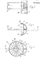
- a partition designated as a whole by 1 is embodied in the exemplary embodiment as a partition which leaves a space 2 above and below it to the ceiling or floor 3.
- This partition wall 1 is formed from rod-shaped elements 4 touching over its length and, according to FIGS. 2 and 5, these rod-shaped elements 4 have transverse openings 5 and a pulling element 6 running through them, which at the two end pieces 7 of the partition wall 1 is still tight is descriptively anchored.
- the tension element 6 is a band spring with an approximately rectangular or elongated cross section, which cross section is arranged in the direction of the elements 4.
- the individual rod-shaped elements 4 are fixed against displacement on the tension element 6 in its orientation direction at least by mutual contact. These elements 4 are arranged vertically in the exemplary embodiment.
- the tension element 6 is preferably a band spring made of metal, which has a correspondingly high strength.
- the sound absorbing elements 4 are 2 and 5 are columnar or cylindrical, touch along surface lines and the tension elements 6 run through their cross-sectional centers, so that a deformation of the entire wall 1 is possible on two sides.
- FIGS. 2 and 5 it is shown that in the interior of the elements 4 there is a core rod or the like which runs over its length and is provided with transverse slots 8 for the respective tension element 6 and which is designed as a support tube 9 in the exemplary embodiment and attached the outside of which a sound-absorbing layer 10 is optionally arranged with an outer cover jacket 11.
- a core rod or the like which runs over its length and is provided with transverse slots 8 for the respective tension element 6 and which is designed as a support tube 9 in the exemplary embodiment and attached the outside of which a sound-absorbing layer 10 is optionally arranged with an outer cover jacket 11.
- a pressure screw or the like can be provided, which preferably pulls the pulling element 6 in the area of the slot 8 and the penetration of the pulling element 6 through the support tube 9 can act on a narrow side and fix non-positively. This can prevent the elements 4, which are relatively soft and resilient on their upper side, from being displaced on the tension elements and thus gaps being formed in the partition wall 1. In the case of elements 4 with a smaller cross section, such additional fastening of the elements 4 is generally not necessary, but is also possible.
- guides 11 penetrating the openings 8 of the sound-absorbing elements 4 and the sound-absorbing layer 10 are preferably made of plastic for the tension element. This improves the stabilization on the tension element, so that the individual elements 4 automatically receive their exact vertical alignment next to one another.
- Fig. 2 it can be seen, also in connection with Fig. 1, that at the support tubes 9 or the like. At least two elements 4, preferably elements 4 located on the edge of the partition 1, are attacked by extensions 12 with adjustable feet 13 can. The extensions 12 can be screwed or clamped into the support tubes 9, for example.
- the adjustable feet 13 have a metal insert 14 to increase their weight and thus also the friction with respect to the base 3 and can additionally be roughened on their underside 15. As a result, they can counteract the restoring forces of the spring-shaped tension elements 6 even when the entire partition 1 is strongly curved. Additional measures for fixing the set curvature of the partition 1 are therefore unnecessary.
- the anchoring of the tension element 6 selected in the exemplary embodiment can be seen on the two end pieces 7 of the partition 1. It is provided that the ends of the tension elements 6 with an anchor part 16, in Embodiment with an armature 16 projecting from two sides of the pulling element 6 and connected with rivets 16.
- the armature part 16 engages with its legs 17 in a hollow profile forming the end pieces 7, which lies against the outermost element 4.
- This hollow profile can have or form at least one connection, not shown in the drawing, for connection to the corresponding hollow profile of a neighboring partition 1, so that several partition walls 1 according to the invention can be put together and connected.
- the hollow profile thus has a double function for connecting and as end piece 7.
- the hollow profile is open on its contact side to the partition 1 and its last element 4 and has 18 undercuts 19 on its edges touching this last element 4 as internal stops for the legs 17 of the anchor part 16.
- the ends 20 of the leg 17 of the armature 16 projecting transversely to the tension element 6 are bent towards the last element 4 and are supported with their end faces on the inside of the undercuts 19 of the hollow profile or of the end piece 7 .
- the tensile forces can be formed by the fact that all the elements 4 lie somewhat against one another under pressure, so that they are somewhat compressed and their restoring forces act as tensile forces on the tensile elements 6.
Landscapes
- Engineering & Computer Science (AREA)
- Architecture (AREA)
- Physics & Mathematics (AREA)
- Electromagnetism (AREA)
- Civil Engineering (AREA)
- Structural Engineering (AREA)
- Building Environments (AREA)
- Agricultural Chemicals And Associated Chemicals (AREA)
- External Artificial Organs (AREA)
- Devices Affording Protection Of Roads Or Walls For Sound Insulation (AREA)
- Floor Finish (AREA)
Priority Applications (1)
| Application Number | Priority Date | Filing Date | Title |
|---|---|---|---|
| AT86113592T ATE45606T1 (de) | 1985-10-16 | 1986-10-02 | Trennwand, insbesondere stellwand. |
Applications Claiming Priority (2)
| Application Number | Priority Date | Filing Date | Title |
|---|---|---|---|
| DE19853536829 DE3536829A1 (de) | 1985-10-16 | 1985-10-16 | Trennwand, insbesondere stellwand |
| DE3536829 | 1985-10-16 |
Publications (3)
| Publication Number | Publication Date |
|---|---|
| EP0219003A2 true EP0219003A2 (fr) | 1987-04-22 |
| EP0219003A3 EP0219003A3 (en) | 1987-05-27 |
| EP0219003B1 EP0219003B1 (fr) | 1989-08-16 |
Family
ID=6283681
Family Applications (1)
| Application Number | Title | Priority Date | Filing Date |
|---|---|---|---|
| EP86113592A Expired EP0219003B1 (fr) | 1985-10-16 | 1986-10-02 | Cloison, en particulier du type paravent |
Country Status (4)
| Country | Link |
|---|---|
| US (1) | US4744184A (fr) |
| EP (1) | EP0219003B1 (fr) |
| AT (1) | ATE45606T1 (fr) |
| DE (2) | DE3536829A1 (fr) |
Families Citing this family (6)
| Publication number | Priority date | Publication date | Assignee | Title |
|---|---|---|---|---|
| US5375641A (en) * | 1993-05-11 | 1994-12-27 | Good Impressions, Inc. | Modular panel system |
| US6088981A (en) * | 1993-07-23 | 2000-07-18 | Office Specialty Inc. | Recessed cover for partition |
| US5881518A (en) * | 1993-10-15 | 1999-03-16 | Hollanding Inc. | Modular partition system |
| US5638650A (en) * | 1993-07-23 | 1997-06-17 | Hollanding Inc. | Retaining clips for office furniture partition |
| WO1997033055A1 (fr) * | 1996-03-07 | 1997-09-12 | Anthony Stansfield | Panneau a chants equipes de cornieres de montage distinctes |
| BE1011814A4 (fr) * | 1997-09-02 | 2000-01-11 | Chenel Guy G | Element de separation en forme de panneau pour realiser des cloisons et presentoirs pour des manifestations temporaires. |
Family Cites Families (17)
| Publication number | Priority date | Publication date | Assignee | Title |
|---|---|---|---|---|
| DE22283C (de) * | A. gendebien in Brüssel | Fächerförmige Ausströmungs-Oeffnungen an Ventilatoren | ||
| US712670A (en) * | 1902-06-05 | 1902-11-04 | Balthaser Haffner | Tie-bar. |
| AT95435B (de) * | 1922-05-27 | 1923-12-27 | Anton Klinger | Holzwand. |
| GB363705A (en) * | 1929-09-25 | 1931-12-18 | Jules Gernaert | Improvements in and relating to the construction of buildings |
| US2094265A (en) * | 1936-10-28 | 1937-09-28 | Curren Fabrihome Corp | Building construction |
| US2208671A (en) * | 1938-03-05 | 1940-07-23 | Gerber Gottlieb | Building structure |
| GB653816A (en) * | 1941-06-18 | 1951-05-23 | Ragnar Mauritz Lublin | Improvements relating to portable screens or partitions |
| NL59427C (fr) * | 1941-12-17 | |||
| US2352420A (en) * | 1943-11-26 | 1944-06-27 | Winters Leo | Flexible wall or partition |
| US2803856A (en) * | 1955-08-15 | 1957-08-27 | Richfield Oil Corp | Building formed of prefabricated panels |
| DE1929201U (de) * | 1963-11-16 | 1965-12-16 | Manfred Gebert | Vorrichtung zur ringzugverankerung fuer fertighaeuser. |
| US3592289A (en) * | 1968-09-06 | 1971-07-13 | Conwed Corp | Freestanding acoustical space divider |
| US4428174A (en) * | 1979-04-04 | 1984-01-31 | Grady Ii Clyde C | Construction system |
| US4559750A (en) * | 1983-12-13 | 1985-12-24 | Nicolas Scourtelis | Room divider |
| IT8421995U1 (it) * | 1984-06-01 | 1985-12-01 | Sacea S A S Di Tirinnanzi Giampietro & C | Insieme di elementi tubolari e di giunti per collegarli fra loro in modo snodato per costituire una parete divisoria di forma variabile. |
| DE8434779U1 (de) * | 1984-11-27 | 1985-04-25 | Basaltin GmbH & Co, 5460 Linz | Wandelement |
| DE3443269A1 (de) * | 1984-11-27 | 1986-05-28 | Basaltin GmbH & Co, 5460 Linz | Wandelement |
-
1985
- 1985-10-16 DE DE19853536829 patent/DE3536829A1/de not_active Withdrawn
-
1986
- 1986-10-02 EP EP86113592A patent/EP0219003B1/fr not_active Expired
- 1986-10-02 DE DE8686113592T patent/DE3665088D1/de not_active Expired
- 1986-10-02 AT AT86113592T patent/ATE45606T1/de not_active IP Right Cessation
- 1986-10-16 US US06/920,258 patent/US4744184A/en not_active Expired - Fee Related
Also Published As
| Publication number | Publication date |
|---|---|
| DE3665088D1 (en) | 1989-09-21 |
| ATE45606T1 (de) | 1989-09-15 |
| US4744184A (en) | 1988-05-17 |
| EP0219003B1 (fr) | 1989-08-16 |
| EP0219003A3 (en) | 1987-05-27 |
| DE3536829A1 (de) | 1987-04-23 |
Similar Documents
| Publication | Publication Date | Title |
|---|---|---|
| EP0440104B1 (fr) | Mur de séparation pour la subdivision d'espaces | |
| DE60208896T2 (de) | Befestigung für wandelemente | |
| DE2556095A1 (de) | Laufsteg fuer daecher | |
| DE1609569C3 (de) | Unterdecke mit mittels Aufhängegliedern an der Rohdecke gehaltenen Tragschienen | |
| DE2652481A1 (de) | Abhaengeelement fuer ein traggerippe zur halterung von zwischendeckenelementen | |
| EP0219003A2 (fr) | Cloison, en particulier du type paravent | |
| DE2809674C2 (de) | Unterdecke | |
| DE3241424C2 (de) | Verbindungseinrichtung | |
| DE2309607C3 (de) | Glaswand | |
| EP0046299A1 (fr) | Poteau pour cloison légère | |
| LU506009B1 (de) | Eine art von baustellensicherheitsnetz | |
| DE2439167A1 (de) | Trennwand | |
| DE944841C (de) | Sieb, insbesondere fuer Setz- und Siebanlagen | |
| DE7513823U (de) | Traegerrost zum befestigen von platten, insbesondere von isolierplatten fuer nichttragende trennwaende, falsche decken, dielen o.dgl. | |
| DE3910254C2 (fr) | ||
| EP3590388B1 (fr) | Châssis de table | |
| DE69000322T2 (de) | Verkleidungselement oder trennwand mit einem blech. | |
| DE3447645C2 (fr) | ||
| DE2315329C3 (de) | Treppe | |
| DE2047380C3 (de) | Versetzbare Trennwand und Verfahren zu deren Herstellung | |
| DE3320383C1 (de) | Verankerungsvorrichtung für eine Tragplatte von säulenartigen Elementen | |
| DE8312857U1 (de) | Tragelement zur halterung von decken-tragschienen und dergleichen | |
| DE7301778U (de) | Verkleidungselement fur einen Radiator | |
| DE202010016970U1 (de) | Raumtrennungssystem | |
| DE2742504A1 (de) | Decken- und wandelemente umfassende variable raumbegrenzung |
Legal Events
| Date | Code | Title | Description |
|---|---|---|---|
| PUAI | Public reference made under article 153(3) epc to a published international application that has entered the european phase |
Free format text: ORIGINAL CODE: 0009012 |
|
| PUAL | Search report despatched |
Free format text: ORIGINAL CODE: 0009013 |
|
| AK | Designated contracting states |
Kind code of ref document: A2 Designated state(s): AT CH DE FR LI NL SE |
|
| AK | Designated contracting states |
Kind code of ref document: A3 Designated state(s): AT CH DE FR LI NL SE |
|
| 17P | Request for examination filed |
Effective date: 19870711 |
|
| 17Q | First examination report despatched |
Effective date: 19880728 |
|
| GRAA | (expected) grant |
Free format text: ORIGINAL CODE: 0009210 |
|
| AK | Designated contracting states |
Kind code of ref document: B1 Designated state(s): AT CH DE FR LI NL SE |
|
| REF | Corresponds to: |
Ref document number: 45606 Country of ref document: AT Date of ref document: 19890915 Kind code of ref document: T |
|
| REF | Corresponds to: |
Ref document number: 3665088 Country of ref document: DE Date of ref document: 19890921 |
|
| PGFP | Annual fee paid to national office [announced via postgrant information from national office to epo] |
Ref country code: SE Payment date: 19891024 Year of fee payment: 4 |
|
| PGFP | Annual fee paid to national office [announced via postgrant information from national office to epo] |
Ref country code: FR Payment date: 19891026 Year of fee payment: 4 |
|
| PGFP | Annual fee paid to national office [announced via postgrant information from national office to epo] |
Ref country code: NL Payment date: 19891031 Year of fee payment: 4 Ref country code: AT Payment date: 19891031 Year of fee payment: 4 |
|
| PGFP | Annual fee paid to national office [announced via postgrant information from national office to epo] |
Ref country code: CH Payment date: 19891114 Year of fee payment: 4 |
|
| ET | Fr: translation filed | ||
| PLBE | No opposition filed within time limit |
Free format text: ORIGINAL CODE: 0009261 |
|
| STAA | Information on the status of an ep patent application or granted ep patent |
Free format text: STATUS: NO OPPOSITION FILED WITHIN TIME LIMIT |
|
| 26N | No opposition filed | ||
| PG25 | Lapsed in a contracting state [announced via postgrant information from national office to epo] |
Ref country code: AT Effective date: 19901002 |
|
| PG25 | Lapsed in a contracting state [announced via postgrant information from national office to epo] |
Ref country code: SE Effective date: 19901003 |
|
| PGFP | Annual fee paid to national office [announced via postgrant information from national office to epo] |
Ref country code: DE Payment date: 19901008 Year of fee payment: 5 |
|
| PG25 | Lapsed in a contracting state [announced via postgrant information from national office to epo] |
Ref country code: LI Effective date: 19901031 Ref country code: CH Effective date: 19901031 |
|
| PG25 | Lapsed in a contracting state [announced via postgrant information from national office to epo] |
Ref country code: NL Effective date: 19910501 |
|
| NLV4 | Nl: lapsed or anulled due to non-payment of the annual fee | ||
| PG25 | Lapsed in a contracting state [announced via postgrant information from national office to epo] |
Ref country code: FR Effective date: 19910628 |
|
| REG | Reference to a national code |
Ref country code: CH Ref legal event code: PL |
|
| REG | Reference to a national code |
Ref country code: FR Ref legal event code: ST |
|
| PG25 | Lapsed in a contracting state [announced via postgrant information from national office to epo] |
Ref country code: DE Effective date: 19920701 |
|
| EUG | Se: european patent has lapsed |
Ref document number: 86113592.9 Effective date: 19910603 |