EP0219015A2 - Epandeur, spécifiquement distributeur pneumatique - Google Patents
Epandeur, spécifiquement distributeur pneumatique Download PDFInfo
- Publication number
- EP0219015A2 EP0219015A2 EP86113704A EP86113704A EP0219015A2 EP 0219015 A2 EP0219015 A2 EP 0219015A2 EP 86113704 A EP86113704 A EP 86113704A EP 86113704 A EP86113704 A EP 86113704A EP 0219015 A2 EP0219015 A2 EP 0219015A2
- Authority
- EP
- European Patent Office
- Prior art keywords
- metering
- electric motors
- distribution machine
- spreading
- machine according
- Prior art date
- Legal status (The legal status is an assumption and is not a legal conclusion. Google has not performed a legal analysis and makes no representation as to the accuracy of the status listed.)
- Granted
Links
Images





Classifications
-
- A—HUMAN NECESSITIES
- A01—AGRICULTURE; FORESTRY; ANIMAL HUSBANDRY; HUNTING; TRAPPING; FISHING
- A01C—PLANTING; SOWING; FERTILISING
- A01C15/00—Fertiliser distributors
- A01C15/04—Fertiliser distributors using blowers
-
- A—HUMAN NECESSITIES
- A01—AGRICULTURE; FORESTRY; ANIMAL HUSBANDRY; HUNTING; TRAPPING; FISHING
- A01C—PLANTING; SOWING; FERTILISING
- A01C19/00—Arrangements for driving working parts of fertilisers or seeders
-
- A—HUMAN NECESSITIES
- A01—AGRICULTURE; FORESTRY; ANIMAL HUSBANDRY; HUNTING; TRAPPING; FISHING
- A01C—PLANTING; SOWING; FERTILISING
- A01C7/00—Sowing
- A01C7/08—Broadcast seeders; Seeders depositing seeds in rows
- A01C7/088—Sectional seeding
-
- A—HUMAN NECESSITIES
- A01—AGRICULTURE; FORESTRY; ANIMAL HUSBANDRY; HUNTING; TRAPPING; FISHING
- A01C—PLANTING; SOWING; FERTILISING
- A01C7/00—Sowing
- A01C7/08—Broadcast seeders; Seeders depositing seeds in rows
- A01C7/10—Devices for adjusting the seed-box ; Regulation of machines for depositing quantities at intervals
- A01C7/102—Regulating or controlling the seed rate
-
- Y—GENERAL TAGGING OF NEW TECHNOLOGICAL DEVELOPMENTS; GENERAL TAGGING OF CROSS-SECTIONAL TECHNOLOGIES SPANNING OVER SEVERAL SECTIONS OF THE IPC; TECHNICAL SUBJECTS COVERED BY FORMER USPC CROSS-REFERENCE ART COLLECTIONS [XRACs] AND DIGESTS
- Y02—TECHNOLOGIES OR APPLICATIONS FOR MITIGATION OR ADAPTATION AGAINST CLIMATE CHANGE
- Y02P—CLIMATE CHANGE MITIGATION TECHNOLOGIES IN THE PRODUCTION OR PROCESSING OF GOODS
- Y02P60/00—Technologies relating to agriculture, livestock or agroalimentary industries
- Y02P60/20—Reduction of greenhouse gas [GHG] emissions in agriculture, e.g. CO2
- Y02P60/21—Dinitrogen oxide [N2O], e.g. using aquaponics, hydroponics or efficiency measures
Definitions
- the invention relates to a distribution machine, in particular pneumatic fertilizer spreader according to the preamble of patent claim 1.
- pneumatic fertilizer spreader is already known from German utility model 80 27 728. With this pneumatic fertilizer spreader, you can use a remote control device to continuously reduce or increase the spread rate during the spreading process. The application rate is reduced or increased evenly across the entire working width or spread of the pneumatic fertilizer spreader.
- the invention is based on the object of being able to vary the spread rate in strip widths which are substantially smaller than the spreading or working width, even in the case of a generic distribution machine with large spreading widths of up to 24 m and more.
- This object is achieved in that the spread rate from the tractor seat during the spreading of material in sections in sections of the spread, preferably starting from a basic spreading quantity value and / or is shrink.
- a different spreading amount can be set for one side or for sections of the spreading width or working width of the machine from the tractor seat during the spreading process than on the other side or as for the remaining parts of the working width or spreading width of the machine. For example, a larger amount of material can be applied on the right side in relation to the basic application quantity compared to the left side, where less material than the basic application quantity is applied.
- the section-by-section reduction of the application rate is of great importance, especially for pneumatic fertilizer spreaders with large working widths of 18 or 24m, if more or less material is used during the application process over a narrow strip that is much narrower than the working width of the fertilizer spreader the remaining working width should be spread, ie that the fertilizer quantity should only be increased or decreased in this narrow area and not over the entire working width of the machine, since over-fertilization or under-fertilization would occur in these other areas, which would affect the yield have a negative impact.
- the measure according to the invention at least the different fertilizer requirements of the soil or the plants for different sections of the spreading width adapt approximately in sections.
- the metering wheels are divided into at least two groups and that the application rate for at least two groups of metering wheels is to be changed. This means that you can set different spread rates for the right and left side during the spread rate process from the tractor seat when dividing into two groups. As a result, significant progress has already been made compared to the prior art, where the spread rate can only be changed over the entire working width. A further improvement can be achieved in that the application rate can be changed in four or more sections independently of one another.
- a simply constructed controllable drive which is compact, results from the fact that at least two controllable electric motors are used to drive the metering roller groups, which can be controlled from the tractor seat by means of a control device arranged on the tractor pulling the distributor, so that both synchronous operation of the Electric motors with the same drive speeds as well as different speeds for the electric motors can be set, and that the electric motors can be stopped and switched on simultaneously and independently of one another.
- the present invention provides a surprisingly simple remedy here by using drive motors which are designed as electric motors and are very easy to control. These electric motors can be controlled and regulated very precisely using relatively simple electronic control electronics.
- the control electronics make it possible to set the synchronous running of the electric motors with the same drive speeds as well as with different speeds in an extremely precise manner in the simplest way.
- the electric motors have a sufficiently large torque to be able to drive the seed wheels, the electric motors then also having to be relatively small, It is provided according to the invention that the electric motors have a reduction gear. The metering wheels are then driven by this reduction gear.
- the invention provides that the electric motors have two speed ranges.
- the respective speed range can already be preselected via the electrical circuit within the electric motors. This is of great importance if either a small or a large application quantity of material is to be applied.
- an accumulator is provided in the power supply system, which is designed according to the invention so strongly that the current intensity supplied by the accumulator is sufficient to be able to drive the metering elements for the purpose of the calibration test if the generator is not driven. This is particularly important if, for example, microgranules are to be turned off.
- the fan is not driven by the tractor PTO. If the blower were to drive the generator via a drive in order to supply the electric motors with current from the generator, the calibration test would be falsified by the air flow generated by the blower.
- the invention provides that at least 4 electric motors are provided, which can then be switched and regulated separately.
- the invention provides that the electric motors can be driven in either direction of rotation. This is important if, for example, after a longer transport trip, the material in the storage container in the area of the metering wheels has solidified to such an extent that the electric motors are unable to rotate the metering wheels due to their very low driving force, the electric motors become briefly driven so that the metering wheels rotate counter to the conveying direction and thus loosen the foremost area of the material which is in contact with the metering wheels and solidifies. After an extremely small reverse rotation, the material is loosened to such an extent that the electric motors are able to drive the metering wheels in the conveying direction.
- a brief reverse rotation is first made before the electric motors drive the metering rollers in their conveying direction.
- the brief reverse rotation can then take place automatically when the electric motors driving the metering elements are switched on, in that a corresponding circuit is provided in the electrical or electronic circuit.
- a manual switch is provided, with which the reverse run for the metering elements driving the electric motors can be switched on. This is particularly important if, during the application process, for example due to impurities that are in the material to be applied and get between the metering wheels and the bottom flaps or lumps of material get between the metering wheels and the bottom flaps, and thus bring the metering elements to a standstill . By simply running backwards Electric motors can then be easily remedied from the tractor seat using the hand switch.
- the metering rollers are arranged to be elastically evasive, at least in groups, so that the metering rollers evade at overload moments and are then pushed back into their original position.
- the metering rollers can dodge when lumps of material or other large-volume bodies, for example stones, etc., get between the metering rollers and the bottom flaps. In this way, these large lumps or foreign bodies are conveyed out of the metering wheels in a simple manner without the dispensing process being interrupted, in that the metering gap automatically enlarges itself as the metering rollers move upwards.
- the metering roller slowly runs back down to its original position.
- This elastically evasible suspension of the metering rollers is also advantageous if, after a long transport route, the material has solidified in the area in front of the metering rollers, the metering roller can initially deflect elastically and then slowly work its way into the material, so after a short time again to return to their original position in order to then dose the material in an exact manner.
- the invention provides that the electric motors have at least one single-stage reduction gear.
- the invention provides that the electric motor or the Reduction gear have a double-sided output. This makes it possible to place the electric motors on both sides of the storage container from the same side onto the drive shafts of the metering wheels.
- the electric motors are switched on in such a way that they are switched on one after the other with a short delay. This ensures that when the electric motors are switched on there is no excessively large current spike, so that the power network or the components generating the current can be designed to be relatively small. The delay only needs to be so short that it is practically imperceptible and is perceived subjectively as if all the motors were switched on at the same time.
- the invention provides that the metering wheels are arranged so that they can be easily removed and installed, so that different types of metering wheels can be installed.
- metering wheels with a relatively coarse toothing are provided for the application of normal fertilizer, while extremely fine toothed metering wheels are provided for the application of microgranules.
- the electric motors with their reduction gears are also arranged to be easily installed and removed. It is then also necessary for the motors and their couplings to be easily uncoupled from the metering wheels or the drive shafts and to be easily coupled again. The motors can then either be laterally displaced or arranged pivotably. It is also entirely possible for the electric motors to be completely detached from the distribution machine via a quick coupling.
- the pneumatic spreader is equipped with a storage container 1, which is not divided into two lower funnel-shaped parts by a roof-shaped central part shown.
- the metering elements 2 are arranged on the metering shaft 3 in front of the outlet openings 4 of the storage container 1.
- These pipelines 6 each have outflow openings, which are arranged next to one another at a distance from one another as seen transversely to the direction of travel.
- An impact body 7 is arranged in front of each outflow opening, on which the material conveyed into the pipes 6 via the metering elements 2 is inflated by means of an air flow which is generated by a blower. By inflating the material particles onto the impact body 7 the total spreading fan composed of individual spreading compartments is created, which is a multiple of the width of the storage container.
- the dosing elements 2 are driven by a controllable drive which, according to the exemplary embodiment according to FIG. 1, consists of the two variator gears 8 and 9.
- the variator gears 8 and 9 are driven by the common chain drive 10 from the drive shaft 5, which is connected to the tractor PTO.
- the variator gears 8 and 9 can be adjusted via the electric servomotors 11 and 12 and the adjusting mechanism 13 and 14 from the tractor seat via the remote control device 15, which is connected to the adjusting motors 11 and 12 via the cables 16.
- the speed of the metering elements 2 and thus the application rate of the pneumatic spreader can be increased or decreased from the tractor seat during the application of material.
- the variator gear 8 is assigned to the metering elements 2 arranged on the right side, while since the variator gear 9 is assigned to the metering elements 2 arranged on the left side of the storage container 1. Between the variator gear 8 and the right metering shaft 3, the reversing gear 17 is also arranged so that the metering elements 2 on the right side of the storage container 1 are driven in the correct direction of rotation.
- the dosing elements 2 are again divided into two groups on each side of the storage container, so that the pneumatic spreader has a total of four groups of dosing elements.
- Each group of metering elements 2 is also assigned a manual transmission 18 or 19, which is also via the Remote control device 15 is to be switched from the tractor seat.
- These manual transmissions 18 and 19 have three switching stages.
- the first group 20 of the metering elements 2 is driven by the variator gear 8 via the reversing gear 17 and the manual gear 18.
- the gearbox 18 and the group 20 of the metering elements 2 has the hollow shaft 21, through which the drive shaft 22 for the group 23 of the metering elements 2 are driven via the gearbox 19.
- the fertilizer from the storage container 1 is supplied to the pipes 6 in controllable quantities via the metering elements 2.
- the material is caught by the air flow generated by a blower and blown to the outflow openings arranged next to one another at different distances transversely to the direction of travel.
- the impact bodies 7, onto which the material is inflated, are arranged in front of the discharge openings of the individual pipes 6.
- the individual baffle compartments 24 are formed which, when assembled, result in the spreading compartments 25.
- the variator gear 8 is adjusted via the remote control device 15, so that the groups 20 and 23 of the metering elements 2 are driven with a smaller number than the metering elements 2 on the left side of the storage container 1 via the metering shaft 3.
- the variator gearbox is again operated via the remote control device 15 adjusted so that the basic speed is set again, ie that the basic spread rate is applied again.
- the variator gear 9 is operated via the remote control device 15 adjusted so that the metering elements 2 on the left side of the storage container are driven at a higher speed than when the material is being dispensed with the basic spreading quantity, so that in the left half of the Working width of the pneumatic fertilizer spreader the higher material is spread in the spreading thickness H.
- the variator gear 9 is again reset from the tractor seat via the remote control device 15, so that the metering elements 2 on the left side of the storage container 1 again at a lower speed than when the larger application rate was applied so that the basic application quantity value is applied again.
- the soil has a very good nutrient supply in the rightmost quarter of the working width A, so that less fertilizer than the basic spreading quantity would have to be spread in this extreme quarter of the working width of the pneumatic fertilizer spreader the spread rate or spread rate is also reduced here.
- the speed of the outermost group 23 of the metering elements 2 is reduced via the switching gear 19.
- the gearbox 19 is also switched over via the remote control device 15 from the tractor seat.
- the fertilizer in the reduced spreading thickness r is spread over the width D according to FIG. 11, while the fertilizer in the spreading strength S is spread over the remaining part of the working width.
- the manual transmission 19 is switched again via the remote control device 15, so that the basic stage is switched on again, so that the fertilizer in the spreading strength S is then applied again in this outermost quarter of the working width of the pneumatic fertilizer spreader .
- the application rate of the pneumatic fertilizer spreader from the tractor seat during the application of material is to be increased and decreased in sections in sections of the spreading width starting from a basic application rate value.
- the metering elements are divided into a total of four groups and the application rate for each group can be changed independently of one another, specifically via the two variator gears 8 and 9 in conjunction with the manual gears 18 and 19 and the manual gears 18 and 19 alone.
- the spread rate can be varied independently of one another for the right and left side of the spread, in that the variator gears 8 and 9 can be adjusted independently of one another via the remote control device 15.
- the application rate is divided into four sections, for example, a different application rate can be set for each section of the working width, which is equal to the basic application rate or larger and smaller than the basic application rate.
- the pneumatic spreader according to FIG. 4 has the storage container 26, which is divided into two funnel-shaped sections by a roof-shaped central part, not shown. In the lower region of the funnel-shaped sections of the storage container 26 there are arranged outlet openings, not shown, in front of which metering elements, also not shown, are arranged. These metering elements are driven by the metering shafts 27 and 28 via the control gear 29. The input shaft 3 of the control gear 29 is driven via a drive shaft, not shown, with a tractor, also not shown, on which the pneumatic fertilizer spreader is attached.
- the control gear 29 is designed as a friction gear.
- the friction wheel gear has the friction disc 31 on which the two friction wheels 32 and 33 rest.
- the friction wheels 32 and 33 are non-positively connected to the metering shafts 27 and 28 via the shafts 34 with the bevel gear 35.
- the shafts 34 are designed as mutually displaceable shafts, so that they can be shifted into one another via the servomotors 36, thus the friction wheels 32 and 33 on the friction disk 31 can be shifted in the radial direction, so that depending on the distance between the friction wheels 32 and 33 the input shaft 30 different output speeds can be set.
- the electric servomotors 36 are connected via cable 37 to a remote control device which is arranged on the tractor which carries the pneumatic fertilizer spreader. So you can from the tractor seat on the remote control device and the servomotors 36 change the speed of the metering shafts 27 and 28 of the metering elements on the left and on the right side of the storage container in a simple manner independently of one another and together
- the application quantity can be changed in sections in sections of the spreading width during the application of material, specifically in two sections, so that a different application rate is independent for the right half of the spreading width can be adjusted from the left half of the spread.
- the 5 has a storage container 38, which is divided into two funnel-shaped halves by a roof-shaped central part.
- the two funnel-shaped lower parts have outlet openings in their lower area, in front of which metering elements are arranged.
- These metering elements are driven by the hydraulic motors 39 and 40.
- the hydraulic motor 39 drives the dosing elements arranged on the right side of the storage container 38, while the hydraulic motor 40 drives the dosing elements arranged on the left side of the storage container.
- the hydraulic motors 39 and 40 are connected via hydraulic hoses 41 to the hydraulic system of the tractor pulling the pneumatic fertilizer spreader. Between the hoses 41, which are connected to the hydraulic system of the tractor, the adjustable flow divider valve 42 to be set via a remote control device is arranged.
- individual control valves are assigned to the oil motors 39 and 40, by means of which the oil quantity flowing to the oil motors 39 and 40 is set. Via the adjustable flow divider valve 42, the speed of the hydraulic motors 39 and 40 and thus the The speed of the dosing elements for the right and left side can be set independently of each other. This makes it possible in a simple manner for the application rate to be increased and decreased in sections during the application of material in sections of the spread, starting from a basic application rate value.
- the pneumatic fertilizer spreader according to FIG. 6 in turn has a storage container 43 which is divided into two funnel-shaped sections by a roof-shaped central part. Outlet openings are arranged in the lower region of the two funnel-shaped sections, in front of which the metering elements 44 are arranged. In Fig. 6 only the dosing elements are shown on the left side of the storage container.
- the metering elements 44 are designed as axially displaceable thrust wheels.
- the metering elements 44 can be moved in the axial direction via the lever 45 and the remote control device 46, which is designed as a Bowden cable, so that the metering elements 44 convey the material with different widths.
- the application rate of the material can be increased or decreased by axially displacing the metering wheels 44.
- the metering elements 44 are driven via a regulating gear 47 via a bottom wheel (not shown).
- the metering elements 44 can be driven at different speeds via the regulating gear 47.
- the spread rate can be set for all dosing elements 44 via the control gear 47 and changed overall from the tractor seat via a remote control device connected to the control gear 47.
- the spread rate in sections of the spread can be changed independently of one another by axially shifting the individual groups of metering elements 44.
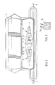
- a storage container 50 which is divided into two lower funnel-shaped parts by a roof-shaped central part, not shown.
- the metering elements 51 are arranged on the metering shaft 52 in front of the outlet openings 53 of the storage container 55.
- the pipes 54 are arranged, which have a different length and extend right and left transversely to the direction of travel.
- These pipelines 54 each have outflow openings, which are arranged next to one another at a distance from one another, as seen transversely to the direction of travel.
- An impact body is arranged in front of each outflow opening, onto which the material conveyed into the piping 54 via the metering elements 51 is inflated by means of an air stream which is generated by a blower. Inflating the material particles onto the impact bodies creates a total spreading fan composed of individual spreading fans, which is a multiple of the width of the storage container.
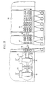
- the metering elements 51 are driven by a controllable drive, which consists of the four electric motors 55 with the reduction gears 56. Two groups of metering elements 51 are arranged on each side of the storage container 50, so that the distribution machine has a total of four groups of metering elements. Each group of metering elements 51 is driven by an electric motor 55 via the reduction gear 56.
- the respective metering shaft 52 of the metering elements 51 is led laterally out of the bearing, so that the reduction gear 56 of the respective electric motor 55 can be arranged on these ends of the metering shaft 52.
- the reduction gear 51 has an inner square, which is placed on the square profile of the metering shaft 52 is.
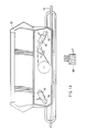
- Each group of metering elements is arranged via the levers 58 to be elastically evasive against the force of the spring 59.
- the bearing for the metering shafts 52 of the metering elements 51 is attached to one end of the levers 58.
- the other end of the lever 58 is pivotally mounted on a wall of the storage container 50 by means of a bolt.
- the pivot axes of the levers 58 and the pivot axes of the electric motors are aligned with one another.
- the inner square 57 of the reduction gear 56 of the electric motor 55 is continuous so that the reduction gear can be plugged onto both ends of one end of the respective metering shaft 52.
- the same electric motors and the same reduction gears can thus be used. This has advantages for the large series.
- the material 60 has strongly solidified in the area of the outlet openings 53 and the area of the metering elements 51, so that when the electric motors 55 are switched on, the material cannot be metered by the metering elements 51 or if larger lumps of caked material 60 were between the metering elements 51 and the base plate 61, the metering elements 51 and the electric motors move upward against the force of the spring 59, for example into the position 62 indicated by dash-dotted lines, so that the electric motors are not overloaded become or there is no damage to the metering elements 51.
- the material which is located in front of the outlet openings 53 and above the base plate 63 is conveyed out by the metering elements 51, so that the metering roller 51 is pulled back or pressed back into its original position by the spring 59 due to the force acting on it.
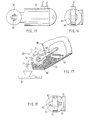
- the reduction gear 63 shown in FIG. 18 has the two output shafts 64 with the two outer square ends 65 so that this reduction gear 63 can also be connected to metering shafts with the flanged electric motor 55 via a corresponding coupling which has an inner edge profile.
- the dosing elements 66 are also arranged in accordance with the dosing elements 51 according to the exemplary embodiment of FIGS. 13 to 5 on both sides of the storage container in front of outlet openings of the storage container 68.
- the metering elements 66 are arranged on the metering shaft 69 in a rotationally fixed manner.
- the metering elements 67 are arranged on the metering shaft 70 designed as a hollow shaft in a rotationally fixed manner.
- the metering elements 66 are driven via the metering shaft 69, which is guided through the hollow shaft 70, by the electric motor 55, which has the reduction gear 56.
- the metering elements 67 are driven via the hollow shaft 70 by the electric motor 55 with the reduction gear 71, which has a corresponding square for the metering shaft 70.
- the regulation and the drive of the metering elements via the electric motors 55 is explained in more detail below with reference to the block diagrams according to FIGS. 23 and 24.
- the metering elements 72 in the machine according to FIG. 20 are in turn arranged on the two sides of the storage container, only the metering elements 72 and 73 arranged on one side of the storage container 73 being shown.
- the dosing elements 72 are arranged on the metering shaft 75, while the metering elements 73 are arranged on the metering shaft 76.
- the electrically switchable coupling 77 is arranged between the metering shaft 75 and the metering shaft 76, so that the metering elements 72 and 73 can be separated or the metering elements 73 can be driven alone.
- the metering elements 72 can thus be stopped, so that the working width is to be reduced over the section which would be sprinkled with the material which the metering elements 72 would convey into the pipelines 54.
- the metering shaft 76 has a square profile on its end led out of the bearing, onto which the inner square of the reduction gear 56, which is flanged to the electric motor 55, is attached.
- the metering elements 72 and 73 are thus driven via the electric motor 55 and the reduction gear 56.
- the drive and the regulation of the speeds of the electric motor 55 or of the metering elements 72 and 73 will be explained later in detail with reference to the block diagrams according to FIGS. 11 and 12.
- the groups of metering elements 78 and 79 are arranged on both sides of the storage container 50, so that the pneumatic fertilizer spreader has a total of four groups of metering elements.
- the metering elements 78 and 79 have a hollow shaft.
- the metering shaft 80 is guided axially displaceably by these hollow shafts.
- the metering shaft 80 has the couplings 81 and 82.
- the metering shaft 80 is driven by the electric motor 55 and the reduction gear 56.
- a sliding clutch is arranged between the reduction gear 56 and the metering shaft 80.
- the swash plate 83 which interacts with the switching mechanism 84, is arranged on the metering shaft 80.
- the switching mechanism 84 can be moved back and forth via a lifting magnet.
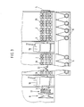
- the storage container 85 which is divided into two lower funnel-shaped parts by a roof-shaped central part, not shown. Dosing elements are arranged in the lower regions of the funnel-shaped parts and are driven by the electric motors 55 and the reduction gears 56. Under the roof-shaped central part, the drive shaft 86 is arranged, which is led out of the wall 87 of the machine to the rear. This drive shaft 86 is connected on its front side to an articulated shaft so that the drive shaft 86 can be driven by the tractor PTO via the articulated shaft.
- the pulley 88 is arranged, from which the blower drive shaft 91 and thus the blower of the pneumatic fertilizer spreader are driven via the V-belt 89 and the pulley 90, which is arranged on the blower drive shaft 91.
- the three-phase generator 92 which, for reasons of cost, is preferably a car or truck alternator, which is driven by the V-belt 89 via the pulley 93.
- This three-phase generator 92 feeds current into On-board power supply 94 of the pneumatic fertilizer spreader, so that the electric motors 55 can be driven in the current generated by the three-phase generator 93.
- this power network 94 also has the power store, which is designed as an accumulator 95.
- the electric motors 55 which are preferably in the form of direct current motors, are regulated in terms of their speed by means of regulation or scattering. This regulation is shown in detail in FIGS. 23 and 24 on the basis of the block diagrams, on which the regulation of the electric motors is also generally explained below.
- the electric motors 55 are arranged such that they can be easily uncoupled from the metering shafts of the metering elements. This is necessary so that the interchangeably arranged dosing elements can easily be exchanged for other dosing elements.
- FIG. 23 shows, as a block diagram, the drive and the regulation of the electric motors 55 driving the metering elements 51, 66, 67, 72, 73, 78 and 79.
- the elements provided for the drive and the control are shown within the area shown with dashed lines.
- the power supply is provided by the power network 96 of the tractor, this power connection being established via a plug.
- the control or regulation of the speed of the drive motors takes place via the potentiometer 97 and via the evaluation circuit 98.
- the sensors 99 are provided, which transmit corresponding signals to the evaluation circuit 98.
- the evaluation circuit 98 is connected via a line to the potentiometers 97, so that their position from the Evaluation circuit 98 is regulated or controlled.
- a display and input monitor 100 arranged on the tractor is connected to the evaluation circuit 98.
- the electrical circuit with the electric motors 55, the sensors 99, the potentiometers 97, the evaluation circuit 98 and the display and operating monitor 100 is supplied with electrical voltage by the tractor power supply 96.
- a setpoint speed of the electric motors 55 and thus also the setpoint speed of the metering elements 51, which is proportional to the application rate of the pneumatic fertilizer spreader per unit area, is specified via the operating monitor 100. This value can either be determined using a calibration test or taken from spreading charts.
- This setpoint is stored in the evaluation circuit 98 via the operating monitor 100.
- the speed of the metering elements 51 is monitored by the sensors 99.
- the respective actual value which is determined by the signals transmitted from the sensors to the evaluation circuit, is displayed on a display panel of the operating monitor 100.
- the electric motors 55 are switched on via the operating monitor 100, so that the metering elements 51 are set in rotation so that they can discharge material.
- the speed of the electric motors 55 is determined by the potentiometers 97, the setting of which is determined in each case by the evaluation circuit 98 and the setpoints entered via the operating monitor.
- the operator monitor 100 can be used to specify that the electric motors 55 work at the same drive speeds, so that synchronous operation of the two electric motors 55 is achieved.
- the operating monitor 100 can be used to set different speeds for the electric motors 55 and thus for the metering elements 51, so that different amounts of material are applied in sections of the spreading width.
- the electric motors can be switched on and off together via the display monitor 100 and the evaluation circuit 98 and also switched on and off independently or separately from one another.
- the electric motors 55 which drive the metering elements 51 and the metering elements not listed in detail in the other figures, can thus be regulated in their drive speed from the tractor seat via the display monitor 100 and the evaluation circuit 98 in such a way that both synchronous running of the electric motors 55 same drive speeds as well as different speeds for the electric motors can be set and furthermore the electric motors 55 can be stopped and switched on simultaneously and independently of one another.
- the speed of the electric motors 55 or the dosing elements 51 can be readjusted via the display monitor 100, since the respective actual speed is transmitted to the evaluation circuit 98 via the sensors 99, which then displays the respective value on the display monitor 100.
- a display that is separate for each motor or each dosing element group 51 is then provided on the display monitor 100.
- the evaluation circuit 98 has a monitoring device which ensures that on the display monitor 100 the standstill of the metering elements 51 or the electric motors 55 and the rotary movement of the electric motors 55 or the metering elements 51 indicates te.
- the metering elements 51 and Electric motors 55 can be driven in either direction of rotation.
- a changeover relay 100a for reversing the polarity is provided in front of the potentiometer 97.
- the electric motors 55 first make a brief reverse rotation which is opposite to the conveying direction before the electric motor 55 drives the metering element 51 in its conveying direction.
- This brief backward running can take place via a separate switch on the display monitor 100, or a circuit can be provided in the evaluation circuit 98 so that the brief backward running of the electric motors 55 or the metering elements 51 takes place automatically when the electric motors driving the metering elements 51 are switched on .
- a manual switch can also be provided on the operating monitor 100, via which the electric motors 55 are also switched to reverse running during the operation or the dispensing process of material. This is important when the metering rollers or the electric motors 55 come to a standstill as a result of foreign bodies blocking the metering elements 51.
- the electric motors 55 are not switched on together at the same time, but rather are switched on for a short time in succession, so that the sum of the starting currents of all electric motors does not have to be applied by the power generator or the power grid.
- the electric motors are then switched on briefly one after the other automatically or automatically via a delay circuit provided in the evaluation circuit. This briefly switching on the electric motors one after the other only needs a short delay that it is practically not perceived.
- the pneumatic fertilizer spreader is moved over the surface of the soil to be spread at a previously selected constant driving speed. This selected driving speed is taken into account when entering the setpoint.
- a driving speed sensor 101 which is attached, for example, to one of the front wheels of a tractor 102 pulling the pneumatic fertilizer control, to transmit the respective actual driving speed to the evaluation circuit 98. It is then possible that the respective actual value of the application rate is then automatically kept constant via the evaluation circuit 98 in conjunction with the potentiometers 97 even when the driving speed changes, by using the potentiometer 90 and the evaluation circuit 98 and the sensor 101, which detects the current Driving speed transmitted to the evaluation circuit 98, the electric motors 55 and thus the speed of the metering elements 51 is controlled accordingly.
- the fertilizer is supplied to the pipes 54 in controllable quantities via the metering elements 51.
- the material is caught by the air flow generated by a blower and to the in different outlets blown side by side seen at different distances from the direction of travel.
- all pipes of the pneumatic fertilizer spreader are supplied with the same amount of material via the metering elements 51, so that the fertilizer is applied in a uniform spreading thickness over the entire spreading width.
- the operating monitor 100 for the electric motor 55 assigned to the right side uses the evaluation circuit 98 and the potentiometer 97 set a lower speed for the electric motor 55 or the metering elements 51, so that a smaller amount of material is fed to the right side of the pipelines, so that the material is spread out on the right side of the working width with a lower spreading strength.
- the metering elements 51 are thus driven by the electric motor 55 at a lower speed than the metering elements on the left side by the electric motor 55.
- the corresponding circuit in the evaluation circuit 98 can be designed such that the application quantity value changes continuously and slowly or else suddenly. If the area in which on the one hand a smaller amount of fertilizer is to be spread has been run over, or one is approaching an area where the basic spreading quantity value is to be spread again in accordance with the grit spreading strength, the operating monitors 100 and Evaluation circuit 98 and the potentiometer 97 set the basic speed for the basic application quantity value on the electric motor assigned to the right-hand side of the metering elements 51, so that the basic application quantity is again applied.
- the Working width over half the working width due to the insufficient nutrient supply, more fertilizer corresponding to the larger spreading spread compared to the basic spreading spread on the right side of the working width, where a larger target value is entered into the evaluation circuit 98 via the operating monitor 100.
- the evaluation circuit 91 transmits corresponding signals to the potentiometer assigned to the left side of the pneumatic fertilizer spreader, so that the potentiometer is adjusted so that the metering elements 51 are then driven at a higher speed via the electric motor 55 assigned to the right side of the metering elements 51. so that a larger amount of material per unit area is spread only over the right section of the spread.
- the potentiometer 97 is again controlled from the tractor seat via the operating monitor 100 and the evaluation circuit 98, so that the electric motor 55 drives the metering elements on the left side of the pneumatic fertilizer spreader again at a speed which the basic speed, which is proportional to the basic spread rate.
- the basic application quantity value is again applied over the entire work of the pneumatic fertilizer spreader.
- the corresponding electric motor that drives the metering elements on the side on which the working width is reduced and on which the fertilizer spreader spread beyond the field edge is activated via the operating monitor 100 and the evaluation circuit 98 would be switched off so that the metering elements come to a standstill.
- the other electric motor 55 is then switched on via the operating monitor 100 and the evaluation circuit 98, so that all metering elements of the pneumatic fertilizer spreader are driven, so that the fertilizer is spread over the entire working width of the pneumatic fertilizer spreader.
- the invention is not limited to an exemplary embodiment with two electric motors 55, but that three, four or more electric motors can be provided as well. In this case, it is then only necessary for the corresponding components to be present more than once or for the evaluation circuit 98 to be expanded accordingly.
- this open-loop or closed-loop control has sensors 103 for detecting the speed of the metering elements 51, the speed of the metering elements 51 being proportional to the application rate of material per unit area.
- this circuit has the DC controllers 104 for regulating the drive speed of the electric motors 55.
- an evaluation circuit 105 is arranged in this regulation, which has the control logic and the drive regulation.
- the respective setpoints or standard sizes of the machine are entered into the evaluation circuit 105 via the display and operating monitor 106.
- the control also has the sensor 107, which transmits the actual driving speed at which the distribution machine is moved across the surface of the ground during the spreading operation to the evaluation circuit 105.
- the components for the application rate control which are decisive for the regulation and control are shown in the area indicated by dashed lines.
- the components arranged in this dashed area are supplied with voltage by a power generator or power generation network.
- the three-phase generator 108 with a rectifier is arranged on the distribution machine itself.
- the on-board power network has the accumulator 109 designed as an energy store.
- the three-phase generator 108 is driven by a drive, for example from the blower shaft of the distributor, from the tractor PTO shaft of the tractor pulling the distributor.
- a drive for example from the blower shaft of the distributor, from the tractor PTO shaft of the tractor pulling the distributor.
- the components of the regulation and control system arranged within the dashed area to be supplied by the on-board electrical system of the tractor which pulls the distribution machine.
- the target application rate or the target speed of the metering elements 51 is stored in the evaluation circuit 105 via the operating and input monitor 106. These setpoints are either determined using a calibration test or taken from spreading charts.
- a signal is sent to the evaluation circuit 105 via the operating monitor 106 that the electric motors 55 drive the metering elements 51, are switched on, so that material is discharged.
- the evaluation circuit 105 can have a control circuit or logic such that when the electric motors 55 are switched on the electric motors initially make a short reverse rotation and only then switch to forward running, in order to then drive the metering wheels 51 in the conveying direction.
- the operating monitor 106 can have keys, via which the metering elements 51 are briefly driven backwards via the electric motors 55, even while the vehicle is being driven or during the application process.
- the electric motors 55 can have two speed levels, which can be realized via two taps of the armature winding of the motor, so that the electric motors 55 can work in the desired speed range with optimal drive torque in the case of large application quantities and small application quantities.
- the respective speed level is effected by switching the changeover switch 110, which is coupled to the evaluation circuit 105. This also saves a reduction stage of a reduction gear.
- the evaluation circuit 105 On the basis of the sensors 103, which transmit the respective actual rotational speed, which is proportional to the application rate, to the evaluation circuit and, due to the driving speed transmitted by the sensor 107, the respectively desired application rate, which is specified via the operating monitor 106 of the evaluation circuit 105, is maintained .
- the operating monitor 106 all electric motors 55 can be switched on and off at the same time or only one or more can be stopped or switched on independently of one another, so that the working width can be switched on and off by separately switching the electric motors 55 and thus stopping the metering elements 51 the distributor can be reduced in sections.
- the evaluation circuit 105 ensures synchronous running of the electric motors with the same drive speeds. It is also possible that the control circuit 106 of the evaluation circuit 105 specifies that the electric motors 55 and thus the dosing elements 51 are driven at different speeds, so that different amounts of material are dosed by the dosing elements 51 over different sections of the spreading width of the distribution machine. so that different amounts of material are distributed in sections.
- the accumulator 109 is designed so strong that the current strength supplied by the accumulator 109 is sufficient to be able to drive the metering elements for the purpose of the calibration test via the electric motor 55 when the generator 108 is not being driven. This is particularly important for a calibration test of microgranules, since the air flow generated by the fan, the shaft of which drives the generator, would falsify the calibration test.
Landscapes
- Life Sciences & Earth Sciences (AREA)
- Soil Sciences (AREA)
- Environmental Sciences (AREA)
- Fertilizing (AREA)
Applications Claiming Priority (4)
| Application Number | Priority Date | Filing Date | Title |
|---|---|---|---|
| DE19853535628 DE3535628A1 (de) | 1985-10-05 | 1985-10-05 | Verteilmaschine, insbesondere pneumatikduengerstreuer |
| DE3535628 | 1985-10-05 | ||
| DE19853539669 DE3539669A1 (de) | 1985-10-05 | 1985-11-08 | Verteilmaschine, insbesondere pneumatikduengerstreuer |
| DE3539669 | 1985-11-08 |
Publications (3)
| Publication Number | Publication Date |
|---|---|
| EP0219015A2 true EP0219015A2 (fr) | 1987-04-22 |
| EP0219015A3 EP0219015A3 (en) | 1988-05-25 |
| EP0219015B1 EP0219015B1 (fr) | 1992-05-13 |
Family
ID=25836739
Family Applications (1)
| Application Number | Title | Priority Date | Filing Date |
|---|---|---|---|
| EP86113704A Expired - Lifetime EP0219015B1 (fr) | 1985-10-05 | 1986-10-03 | Epandeur, spécifiquement distributeur pneumatique |
Country Status (2)
| Country | Link |
|---|---|
| EP (1) | EP0219015B1 (fr) |
| DE (1) | DE3539669A1 (fr) |
Cited By (9)
| Publication number | Priority date | Publication date | Assignee | Title |
|---|---|---|---|---|
| EP0453861A1 (fr) * | 1990-04-23 | 1991-10-30 | Amazonen-Werke H. Dreyer GmbH & Co. KG | Epandeur |
| WO2012014173A3 (fr) * | 2010-07-29 | 2012-03-22 | Michele Antonio Del Giudice | Machine conçue pour distribuer des produits en poudre dans le domaine de l'agriculture |
| EP3409090A1 (fr) * | 2017-05-29 | 2018-12-05 | Rauch Landmaschinenfabrik Gmbh | Machine d'épandage pneumatique et procédé de distribution de produit à épandre au moyen de ladite machine d'épandage pneumatique |
| EP3508047A1 (fr) * | 2018-01-09 | 2019-07-10 | Lehner Agrar GmbH | Dispositif d'épandage du produit d'épandage sur des surfaces agricoles |
| WO2019157094A1 (fr) * | 2018-02-06 | 2019-08-15 | Intelligent Agricultural Solutions Llc | Courroie de commande sectionnelle |
| CN115997536A (zh) * | 2022-12-10 | 2023-04-25 | 东北农业大学 | 一种配比可调式无人机变量排肥装置 |
| US11744169B2 (en) | 2019-11-14 | 2023-09-05 | Cnh Industrial Canada, Ltd. | Particulate material metering system for an agricultural implement |
| US11765991B2 (en) | 2019-11-14 | 2023-09-26 | Cnh Industrial Canada, Ltd. | Particulate material metering system for an agricultural implement |
| US12268119B2 (en) | 2011-03-10 | 2025-04-08 | Cnh Industrial Canada, Ltd. | Agricultural metering system having multiple meter rollers |
Families Citing this family (4)
| Publication number | Priority date | Publication date | Assignee | Title |
|---|---|---|---|---|
| DE4410365A1 (de) * | 1994-03-25 | 1995-09-28 | Amazonen Werke Dreyer H | Pneumatische Verteilmaschine |
| DE102005012578B4 (de) * | 2005-03-18 | 2014-07-03 | Amazonen-Werke H. Dreyer Gmbh & Co. Kg | Landwirtschaftliche Verteilmaschine |
| AT14771U1 (de) * | 2015-04-17 | 2016-05-15 | Apv Tech Produkte Gmbh | Sämaschine |
| US12349614B2 (en) | 2021-11-10 | 2025-07-08 | Deere & Company | Air seeding turn compensation using yaw rate from sensor on towing vehicle |
Family Cites Families (8)
| Publication number | Priority date | Publication date | Assignee | Title |
|---|---|---|---|---|
| DE666247C (de) * | 1938-10-15 | Jakob Botsch | Saemaschine mit stufenlosem Antrieb der Saeraeder | |
| FR775571A (fr) * | 1933-05-16 | 1935-01-04 | Rudolf Sack | Dispositif d'entraînement pour semoirs en lignes ou pour distributeurs d'engrais à organes distributeurs rotatifs |
| DE831467C (de) * | 1950-12-12 | 1952-02-14 | Amazonenwerk H Dreyer | Schwenkbare Saewellenlagerung an Saemaschinen |
| FR2063616A6 (fr) * | 1969-10-23 | 1971-07-09 | Roger | |
| DE2520709A1 (de) * | 1975-05-09 | 1976-11-18 | Wilhelm Prof Dr Ing Dr Knolle | Verfahren und vorrichtung zum von ackerunebenheiten und fahrgeschwindigkeit unabhaengig stufenlos regelbarem antrieb von einzelkornsaemaschinen |
| DE3116774C2 (de) * | 1981-04-28 | 1983-07-14 | Amazonen-Werke H. Dreyer Gmbh & Co Kg, 4507 Hasbergen | Maschine zum Ausbringen von körnigem Material |
| DE3310424C2 (de) * | 1983-03-23 | 1986-10-09 | Rauch Landmaschinenfabrik GmbH, 7573 Sinzheim | Vorrichtung zum Ausbringen von Schüttgut, wie Dünger, Saatgut od.dgl. |
| FR2544956A3 (fr) * | 1983-04-26 | 1984-11-02 | Amazonen Werke Dreyer H | Machine pour l'epandage de matieres en grains |
-
1985
- 1985-11-08 DE DE19853539669 patent/DE3539669A1/de not_active Withdrawn
-
1986
- 1986-10-03 EP EP86113704A patent/EP0219015B1/fr not_active Expired - Lifetime
Cited By (10)
| Publication number | Priority date | Publication date | Assignee | Title |
|---|---|---|---|---|
| EP0453861A1 (fr) * | 1990-04-23 | 1991-10-30 | Amazonen-Werke H. Dreyer GmbH & Co. KG | Epandeur |
| WO2012014173A3 (fr) * | 2010-07-29 | 2012-03-22 | Michele Antonio Del Giudice | Machine conçue pour distribuer des produits en poudre dans le domaine de l'agriculture |
| US12268119B2 (en) | 2011-03-10 | 2025-04-08 | Cnh Industrial Canada, Ltd. | Agricultural metering system having multiple meter rollers |
| EP3409090A1 (fr) * | 2017-05-29 | 2018-12-05 | Rauch Landmaschinenfabrik Gmbh | Machine d'épandage pneumatique et procédé de distribution de produit à épandre au moyen de ladite machine d'épandage pneumatique |
| EP3508047A1 (fr) * | 2018-01-09 | 2019-07-10 | Lehner Agrar GmbH | Dispositif d'épandage du produit d'épandage sur des surfaces agricoles |
| WO2019157094A1 (fr) * | 2018-02-06 | 2019-08-15 | Intelligent Agricultural Solutions Llc | Courroie de commande sectionnelle |
| US11744169B2 (en) | 2019-11-14 | 2023-09-05 | Cnh Industrial Canada, Ltd. | Particulate material metering system for an agricultural implement |
| US11765991B2 (en) | 2019-11-14 | 2023-09-26 | Cnh Industrial Canada, Ltd. | Particulate material metering system for an agricultural implement |
| CN115997536A (zh) * | 2022-12-10 | 2023-04-25 | 东北农业大学 | 一种配比可调式无人机变量排肥装置 |
| CN115997536B (zh) * | 2022-12-10 | 2023-12-29 | 东北农业大学 | 一种配比可调式无人机变量排肥装置 |
Also Published As
| Publication number | Publication date |
|---|---|
| DE3539669A1 (de) | 1987-05-14 |
| EP0219015A3 (en) | 1988-05-25 |
| EP0219015B1 (fr) | 1992-05-13 |
Similar Documents
| Publication | Publication Date | Title |
|---|---|---|
| DE102004030240B4 (de) | Pneumatischer Streuer zum Verteilen von Streugut, insbesondere Dünger, Saatgut oder dergleichen | |
| EP0219015B1 (fr) | Epandeur, spécifiquement distributeur pneumatique | |
| WO2020035337A1 (fr) | Élément semeur pour un semoir monograine | |
| EP0445842A1 (fr) | Distributeur d'engrais centrifuge avec trémie | |
| EP3662734B1 (fr) | Système de commande et / ou de régulation pour une machine de distribution agricole, machine de distribution agricole et procédé de commande et / ou de régulation d'une machine de distribution agricole | |
| EP0281761B1 (fr) | Semoir monograine | |
| DE102007038510B4 (de) | Vorrichtung zum Dosieren und Verteilen von landwirtschaftlichen und kommunalen Schüttgütern | |
| EP0278251B1 (fr) | Epandeur à disques centrifuges | |
| DE19929356C2 (de) | Schleuderstreuer | |
| DE3719269A1 (de) | Hydraulikanlage fuer eine landwirtschaftliche verteilmaschine | |
| DE3642502A1 (de) | Landwirtschaftliche geraetekombination | |
| EP3821689A1 (fr) | Agencement de transport pour effluents d'élevage ainsi que produit programme informatique et procédé d'épandage des effluents d'élevage | |
| DE3823532A1 (de) | Maschine zum ausbringen von koernigem material | |
| EP0192089A2 (fr) | Distributeur à disques, spécialement pour engrais en granulés | |
| DE10248613B4 (de) | Streugerät | |
| DE4244913C2 (de) | Elektronische Anzeigevorrichtung für einen Zentrifugalstreuer | |
| DE2807521C3 (de) | An einen Schlepper ankuppelbare Drillmaschine | |
| DE4016595C2 (de) | Verteilmaschine | |
| DE3616538C2 (fr) | ||
| DE2752590A1 (de) | Maschine zum pneumatischen ausbringen von koernigem material | |
| EP1293114B1 (fr) | Epandeur agricole avec système pour l'élimination automatique d'obstructions | |
| DE2518397A1 (de) | Maschine zum verteilen von streufaehigem material | |
| EP1695609B1 (fr) | Tondeuse à gazon | |
| EP0979898B1 (fr) | Dispositif d'épandage | |
| DE2453993A1 (de) | Maschine zum verteilen von gekoerntem streugut |
Legal Events
| Date | Code | Title | Description |
|---|---|---|---|
| PUAI | Public reference made under article 153(3) epc to a published international application that has entered the european phase |
Free format text: ORIGINAL CODE: 0009012 |
|
| AK | Designated contracting states |
Kind code of ref document: A2 Designated state(s): ES FR GB NL SE |
|
| PUAL | Search report despatched |
Free format text: ORIGINAL CODE: 0009013 |
|
| AK | Designated contracting states |
Kind code of ref document: A3 Designated state(s): ES FR GB NL SE |
|
| 17P | Request for examination filed |
Effective date: 19880505 |
|
| 17Q | First examination report despatched |
Effective date: 19900423 |
|
| GRAA | (expected) grant |
Free format text: ORIGINAL CODE: 0009210 |
|
| AK | Designated contracting states |
Kind code of ref document: B1 Designated state(s): ES FR GB NL SE |
|
| PG25 | Lapsed in a contracting state [announced via postgrant information from national office to epo] |
Ref country code: SE Effective date: 19920513 |
|
| ET | Fr: translation filed | ||
| PG25 | Lapsed in a contracting state [announced via postgrant information from national office to epo] |
Ref country code: ES Free format text: LAPSE BECAUSE OF FAILURE TO SUBMIT A TRANSLATION OF THE DESCRIPTION OR TO PAY THE FEE WITHIN THE PRESCRIBED TIME-LIMIT Effective date: 19920814 |
|
| GBT | Gb: translation of ep patent filed (gb section 77(6)(a)/1977) | ||
| PGFP | Annual fee paid to national office [announced via postgrant information from national office to epo] |
Ref country code: GB Payment date: 19920924 Year of fee payment: 7 |
|
| PGFP | Annual fee paid to national office [announced via postgrant information from national office to epo] |
Ref country code: FR Payment date: 19921006 Year of fee payment: 7 |
|
| PGFP | Annual fee paid to national office [announced via postgrant information from national office to epo] |
Ref country code: NL Payment date: 19921031 Year of fee payment: 7 |
|
| PLBI | Opposition filed |
Free format text: ORIGINAL CODE: 0009260 |
|
| 26 | Opposition filed |
Opponent name: C. VAN DER LELY N.V. Effective date: 19930212 |
|
| NLR1 | Nl: opposition has been filed with the epo |
Opponent name: C.VAN DER LELY N.V. |
|
| RDAG | Patent revoked |
Free format text: ORIGINAL CODE: 0009271 |
|
| STAA | Information on the status of an ep patent application or granted ep patent |
Free format text: STATUS: PATENT REVOKED |
|
| 27W | Patent revoked |
Effective date: 19931231 |
|
| GBPR | Gb: patent revoked under art. 102 of the ep convention designating the uk as contracting state |
Free format text: 931231 |
|
| NLV4 | Nl: lapsed or anulled due to non-payment of the annual fee |