EP0219098A1 - Dispositif de traitement des signaux d'image pour un système de représentation image ultrasonore et dispositif de représentation - Google Patents
Dispositif de traitement des signaux d'image pour un système de représentation image ultrasonore et dispositif de représentation Download PDFInfo
- Publication number
- EP0219098A1 EP0219098A1 EP86114220A EP86114220A EP0219098A1 EP 0219098 A1 EP0219098 A1 EP 0219098A1 EP 86114220 A EP86114220 A EP 86114220A EP 86114220 A EP86114220 A EP 86114220A EP 0219098 A1 EP0219098 A1 EP 0219098A1
- Authority
- EP
- European Patent Office
- Prior art keywords
- filter
- value
- image
- values
- amplitude
- Prior art date
- Legal status (The legal status is an assumption and is not a legal conclusion. Google has not performed a legal analysis and makes no representation as to the accuracy of the status listed.)
- Granted
Links
Images


Classifications
-
- G—PHYSICS
- G01—MEASURING; TESTING
- G01S—RADIO DIRECTION-FINDING; RADIO NAVIGATION; DETERMINING DISTANCE OR VELOCITY BY USE OF RADIO WAVES; LOCATING OR PRESENCE-DETECTING BY USE OF THE REFLECTION OR RERADIATION OF RADIO WAVES; ANALOGOUS ARRANGEMENTS USING OTHER WAVES
- G01S7/00—Details of systems according to groups G01S13/00, G01S15/00, G01S17/00
- G01S7/52—Details of systems according to groups G01S13/00, G01S15/00, G01S17/00 of systems according to group G01S15/00
- G01S7/52017—Details of systems according to groups G01S13/00, G01S15/00, G01S17/00 of systems according to group G01S15/00 particularly adapted to short-range imaging
- G01S7/52053—Display arrangements
- G01S7/52057—Cathode ray tube displays
- G01S7/5206—Two-dimensional coordinated display of distance and direction; B-scan display
- G01S7/52065—Compound scan display, e.g. panoramic imaging
-
- G—PHYSICS
- G01—MEASURING; TESTING
- G01S—RADIO DIRECTION-FINDING; RADIO NAVIGATION; DETERMINING DISTANCE OR VELOCITY BY USE OF RADIO WAVES; LOCATING OR PRESENCE-DETECTING BY USE OF THE REFLECTION OR RERADIATION OF RADIO WAVES; ANALOGOUS ARRANGEMENTS USING OTHER WAVES
- G01S7/00—Details of systems according to groups G01S13/00, G01S15/00, G01S17/00
- G01S7/52—Details of systems according to groups G01S13/00, G01S15/00, G01S17/00 of systems according to group G01S15/00
- G01S7/52017—Details of systems according to groups G01S13/00, G01S15/00, G01S17/00 of systems according to group G01S15/00 particularly adapted to short-range imaging
- G01S7/52023—Details of receivers
- G01S7/52025—Details of receivers for pulse systems
- G01S7/52026—Extracting wanted echo signals
- G01S7/52028—Extracting wanted echo signals using digital techniques
-
- G—PHYSICS
- G01—MEASURING; TESTING
- G01S—RADIO DIRECTION-FINDING; RADIO NAVIGATION; DETERMINING DISTANCE OR VELOCITY BY USE OF RADIO WAVES; LOCATING OR PRESENCE-DETECTING BY USE OF THE REFLECTION OR RERADIATION OF RADIO WAVES; ANALOGOUS ARRANGEMENTS USING OTHER WAVES
- G01S7/00—Details of systems according to groups G01S13/00, G01S15/00, G01S17/00
- G01S7/52—Details of systems according to groups G01S13/00, G01S15/00, G01S17/00 of systems according to group G01S15/00
- G01S7/52017—Details of systems according to groups G01S13/00, G01S15/00, G01S17/00 of systems according to group G01S15/00 particularly adapted to short-range imaging
- G01S7/52077—Details of systems according to groups G01S13/00, G01S15/00, G01S17/00 of systems according to group G01S15/00 particularly adapted to short-range imaging with means for elimination of unwanted signals, e.g. noise or interference
-
- H—ELECTRICITY
- H03—ELECTRONIC CIRCUITRY
- H03H—IMPEDANCE NETWORKS, e.g. RESONANT CIRCUITS; RESONATORS
- H03H17/00—Networks using digital techniques
- H03H17/02—Frequency selective networks
- H03H17/04—Recursive filters
-
- H—ELECTRICITY
- H04—ELECTRIC COMMUNICATION TECHNIQUE
- H04N—PICTORIAL COMMUNICATION, e.g. TELEVISION
- H04N5/00—Details of television systems
- H04N5/14—Picture signal circuitry for video frequency region
- H04N5/21—Circuitry for suppressing or minimising disturbance, e.g. moiré or halo
Definitions
- the invention relates to a method for generating ultrasound cross-sectional images of a body, in which method a plurality of successive, at least partially overlapping, line-by-line scans of the body, carried out after the pulse echo method in a scanning plane, and image signals in digital form that generate the received echoes correspond, each scan comprising a predetermined number of scan lines and each of these a predetermined number of scan points, a predetermined time interval being provided between corresponding scan points of successive scans.
- the invention also relates to an image signal processing device that can be used to carry out the method according to the invention and an ultrasound imaging device that contains such a device.
- the object of the invention is therefore to remedy the disadvantage mentioned above.
- the image signal which corresponds in each case to one of the displayed pixels, is generated by a combination of image signals, the corresponding sampling points in succession Corresponds to scans, the combination of these image signals being carried out by time-discrete non-linear filtering thereof, each of the filter coefficients being variable as a function of the amplitude of the input signal of the filter.
- the invention also relates to an ultrasound imaging device for generating ultrasound cross-sectional images of a body, with which device a multiplicity of successive, at least partially overlapping, line-by-line scans of the body can be carried out according to the pulse echo method in order to image signals in digital form to generate, corresponding to the received echoes, each scan a predetermined number of scan lines and each of these comprises a predetermined number of scanning points, a predetermined time interval being provided between corresponding scanning points of successive scans, and which device comprises an ultrasound scanning device, a transmitter connected thereto, a receiver connected to the ultrasound scanning device, a television monitor connected to the receiver, and one with contains the control unit connected to the transmitter, the receiver, and the television monitor, wherein the receiver contains a detector circuit for generating an analog output signal.
- the device according to the invention is characterized in that it contains the image signal processing device described above.
- the advantages achieved by the invention are essentially to be seen in the fact that a considerable reduction in noise is achieved without movements in the area under examination causing the resulting resulting image to be blurred. It has now become possible to simultaneously produce easily recognizable ultrasound images of moving organs or parts of organs (e.g. heart valves) and to improve the quality of such images by reducing noise.
- the invention also has the advantage that its implementation requires a relatively low amount of circuitry.
- FIG 1 shows the block diagram of an ultrasound imaging device for carrying out the method according to the invention.
- a pulsed transmitter 15 controls an ultrasound transducer 10 of a scanning device 14 4 via a duplexer 14.
- This device is a mechanical sector scanner.
- the received echo signal passes through the duplexer l4 to the input of a receiver 26.
- the input of a depth compensation amplifier l6 is also the input of the receiver 26.
- the amplifier l6 is followed by a logarithmic amplifier l7 which supplies an output signal which is proportional over a certain range to the logarithm of the input signal.
- the exit of the loga rithmic amplifier l7 is connected via a line 29 to the input of a detector l8. With this detector, for example, absolute value formation and low-pass filtering of the output signal of the logarithmic amplifier 17 are carried out.
- the output signal of the detector 18 is output via a line 91.
- This signal is converted from analog to digital in the image signal processing device 27 using an analog / digital converter 19.
- the output signal of the converter 19 is fed via a bus line 3l to the input of a non-linear digital filter 2l.
- the output signal of the filter 2l is output via a bus line 36 and temporarily stored in an image memory / standard converter 22.
- the content of the image memory / standard converter 22 is read out.
- the signal read out is converted digitally to analog using a digital / analog converter 23.
- the output signal of the converter 23 is the output signal of the image signal processing device 27. This output signal is fed to a television monitor 24 as a television standard signal.
- the ultrasonic transducer l0 is moved by a motor l2 which is controlled by a motor control l3.
- the control electronics 25 shown give command and synchronization signals to all other blocks shown in FIG.
- the method according to the invention can also be used in ultrasound imaging in which the scanning patterns used only partially overlap.
- the method according to the invention can therefore also be carried out with the ultrasound device / image device shown in FIG. 2 by a block diagram, which works with an electronic compound scanner.
- the ultrasound imaging device contains a transducer arrangement II4, a transducer connection device 16L, a transmitter 155L, a receiver 26L, a television monitor 24 and a control unit 25l.
- the transducer arrangement II4 contains an elongated arrangement of adjoining transducer elements.
- the transducer arrangement II4 can have a flat radiation surface 71. In a preferred embodiment, however, its radiation surface has a certain curvature, which causes the ultrasound waves to be focused in a plane perpendicular to the scanning plane.
- the transducer connection device 16l contains an element selection device 160 with which each transducer element the converter arrangement ll4 can optionally be connected to a suitable connection of the transmitter l5l.
- the converter connection device l6l is connected via a bus line l52 or 262 to the transmitter l5l or to the receiver 26l.
- the receiver 26l has a structure similar to that of the receiver 26 in FIG. 1, but additionally contains means (not shown in FIG. 2) for adding the echo signals coming from the individual transducer elements to form a resulting echo signal.
- the receiver 26l contains i.a. a detector circuit 18 such as that from the receiver 26 and an image signal processing device 271, which is described in detail below with reference to FIG. 3.
- the output signal of the detector circuit 18 is fed to the input of the image signal processing device 27l via a line 9l.
- the image signals at the output of the device 271 are sent to the television monitor 24 via a line 36l supplied.
- the control unit 25l contains the necessary means for controlling the function of all other blocks shown in FIG. 2.
- the use of the image device shown there for examining a body part 11 of a patient is shown schematically.
- the transducer arrangement II4 is placed on the skin III of the body part 11 to be examined, a transfer gel II3 being placed between the radiation surface of the transducer device and the patient's skin.
- the imaging system shown in Fig. 2 is operated in such a way that with the transducer arrangement II4 at least two different, partially overlapping scans are carried out in the scanning plane according to the pulse echo method in order to produce a composite cross-sectional image, e.g. by an internal organ l2l.
- a composite cross-sectional image e.g. by an internal organ l2l.
- three such scans 1, 2, 3 carried out in rapid succession.
- groups of transducer elements of transducer arrangement II4 are used in rapid succession, which send ultrasonic pulses in a specific direction and receive the corresponding echoes.
- the examined body part is irradiated with a rapid sequence of mutually parallel ultrasound beams in each of the scans 1, 2 or 3.
- the corresponding beams (also called scan lines here) 4, 5 and 6 are shown with different lines for each of the scans 1, 2, 3.
- the examined body part is irradiated with the composite scanning pattern shown in FIG. 1 in a very short time.
- the transmit signals for the transducer elements of transducer arrangement ll4 are generated in transmitter 15l, and those of Echo signals supplied to transducer elements are fed to the receiver 261 via the line 262.
- the received echo signals are emitted at the output of detector 18 and via line 91.
- the image signal processing device 27l described in detail below serves, among other things. to electronic compounding, i.e. assemble these frames to produce a composite image called the compound image.
- the image signal processing device 27l in FIG. 2 contains the same blocks l9, 2l, 22 and 23 as the device 27 in FIG. 1 and additionally one between the image memory / standard converter 22 and the digital / analog Converter 23 switched on evaluation unit 22l.
- This unit serves to combine the image signals read from the image memory / standard converter 22 with one another in order to generate the compound image, e.g. by averaging the image signals.
- the output signal of the image signal processing device 27l is fed via line 36l to the television monitor.
- a compound image is then displayed on the television monitor 24, i.e. an image generated by the electronic composition of still images mentioned above.
- the present invention relates in particular to the design of the image signal processing device 27 in FIGS. 1 and 27l in FIG. 2.
- This device is in particular characterized in that it contains a non-linear digital filter 2l which is located between the analog / digital converter l9 and the digital / Analog converter 23 is turned on, and that the coefficients of the filter 2l are variable as a function of the amplitude of its input signal to the filter.
- the filter 2l between the analog / digital converter 19 and the image memory / standard converter 22 is switched on.
- Filter 2l can, however, also be connected downstream of block 22 in FIG. 1 or FIG. 2, or block 22l in FIG. 3, if this is taken into account when determining the filter coefficients.
- FIG. 4 The basic circuit of a first embodiment of the filter 2l is shown in FIG. 4.
- This filter is a transversal filter of the first order and contains a delay element 34, coefficient multipliers 32 and 35 and an adder 33.
- the signals supplied by the output of the analog / digital / converter 19 are supplied to the input of the filter 2l via the bus line 3l.
- the output signal of filter 2l is output via line 36.
- a coefficient B1 is introduced with the coefficient multiplier 32 and a coefficient B2 is introduced with the coefficient multiplier 35.
- the delay element 34 delays the input signal of the filter 2l, the duration of which is equal to the predetermined time interval which is provided between corresponding sampling points of successive samples.
- the coefficient multipliers 32 and 35 are set up so that each of the filter coefficients B1 and B2 is variable as a function of the amplitude of the input signal of the filter.
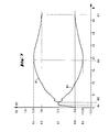
- FIG. 6 shows a diagram from which an example of the variation of the filter coefficients B1 and B2 as a function of the amplitude N of the input signal of the filter can be seen.
- other values of Kl, K2 and Kl3 can also be used.
- the course of B1 with respect to the course of B2 is at least approximately the same as that shown in FIG. 6.
- Each of the coefficient multipliers 32 and 35 is a PROM, for example.
- the delay element 34 is, for example, an image memory used as a digital delay line.
- the filter 2l has the circuit according to FIG. 4 and works with the filter coefficients according to FIG. 6, a non-linear filtering of the input signals is carried out, which has the effect that input signals which have a relatively small amplitude over two successive images are averaged, while input signals that have a relatively large amplitude are not averaged at all and go directly to the output of the filter.
- This has the following effects: - A blurring of the displayed image by averaging echo signals that have relatively large amplitudes is avoided. - The mapping of movements, which are generally represented by relatively large echo signals, is improved compared to previously known systems in which averaging of all echo signals - regardless of their amplitude - is carried out by linear filtering of the echo signals. - By averaging the relatively small echo signals, an improvement in the signal-to-noise ratio of the resulting image is achieved compared to known systems in which no measures are provided to improve this ratio.
- a second embodiment of the filter 2l also has the circuit according to FIG. 4, but works with different filter coefficients.
- An example of the variation of these coefficients as a function of the amplitude of the input signal of the filter can be seen from the diagram shown in FIG. 7.
- K3, K4, K5, K6 and K7 can also be used, provided that K6 is less than 0 and that Kll is equal to or less than 0.
- the course of B1 with respect to the course of B2 is at least approximately the same as that shown in FIG. 7.
- this second embodiment of the filter 2l ie the embodiment with the circuit according to FIG. 4 and the filter coefficients according to FIG. 7, in addition to the effects already mentioned above, the effects with the first embodiment according to FIG 4 and 6 are achieved, a highlighting of the input signals achieved, which correspond to movements in the examined area.
- This second embodiment of the filter 2l therefore also has the function of a fixed character eraser (moving target indicator).
- the input signals of the filter can be averaged over a maximum of 2 images.
- This limit can be exceeded with a recursive filter circuit, such as that shown in Fig. 5, if it works with filter coefficients A, B1 and B2, e.g. vary according to the diagram shown in Fig. 8 as a function of the amplitude N of the input signal of the filter.
- the filter circuit according to FIG. 5 differs from that according to FIG. 4 only in that a feedback path is provided in the circuit according to FIG. 5, in which a coefficient A is introduced by means of a coefficient multiplier 42, and in that the signal and the feedback that results therefrom Input signal of the filter can be added using an adder 4l.
- K7, K8 and Kl2 can also be used, provided that K7 is greater than K8, K8 is greater than Kl2, and that Kl2 is equal to or greater than 0.
- the course of each of the coefficients A, B1 and B2 with respect to the course of the other two coefficients is at least approximately the same as shown in FIG. 8.
- the filter coefficients are determined as follows:
- a function A (N) is chosen. With the values of the coefficient A chosen in this way, the coefficients B1 and B2 are then determined using equations (II) and (III). It is then checked whether the step response of the filter for each value of the amplitude N of the input signal, i.e. is stable for each group of values of the coefficients A, Bl, B2 corresponding to such a value of N, and whether the filter leaves the gray tone distribution of a static image unchanged. If this is not the case, the procedure just described has to be carried out with a new selected function A (N), etc.
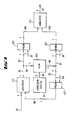
- FIG. 9 shows the block diagram of a circuit with which either a filter 2l according to FIG. 4 with the filter coefficients according to FIG. 6 or FIG. 7, or a filter 2l according to FIG. 5 with the filter coefficients according to FIG. 8 can be produced .
- the input signal is fed to the input of the filter according to FIG. 9 via a 6-bit bus line 3l.
- This bus line is connected to a first input of an adder 4ll.
- the output of the adder 4ll is connected via 7-bit bus lines 9l-93 to a first address input of a PROM 32l and to the data input of a RAM 34l.
- the function of the RAM 34l is controlled by an address counter 94, the output of which is connected to the address input of the RAM 34l via a 17-bit bus line 95.
- the data output of RAM 34l is connected via 7-bit bus lines 96-98 to a first address input of a PROM 35l and to a first address input of a PROM 42l.
- the output of the PROM 42l is connected via a 7-bit bus line 99 connected to a second input of the adder 4ll.
- the outputs of the PROM 32l and 35l are each connected to a first and a second input of an adder 33l via a 7-bit bus line l0l or l02.
- the output signal of the adder 33l is output via a 6-bit bus line 36.
- the PROM 32l, 35l and 42l are used as coefficient multipliers.
- the following coefficients can be optionally introduced:
- each of the PROM 32l, 35l, 42l there are 512 different addresses which are multiplexed via a 9-bit address bus. A word with an 8-bit word length can be read in each address. According to the above description of the block diagram according to FIG. 9, only 7 bits are used.
- Each of the PROM 32l, 35l, 42l has a second address input. A control signal is fed to each of these inputs via a 2-bit bus line 87, 88 and 89, respectively. This control signal is used to select the group of coefficients to be introduced with each PROM.
- the 2-bit control signal can have 4 different values. This means that 4 different groups of filter coefficients per PROM and thus 4 different filters can be selected.
- the RAM 34l has the function of a delay element.
- the storage locations for the image signals are arranged in a matrix with 256 columns and 512 rows. This arrangement corresponds to the arrangement of the scanned points and the arrangement of the displayed pixels.
- Each image signal stored there is encoded in the form of a 7-bit word.
- Control of RAM 34l by address counter 94 causes RAM 34l to function as a shift register. In this way, the image signal for a sampled point of the current scan and the image signal for the same point in the previous scan at the output of the RAM 34l are simultaneously available at the input of the RAM 34l.
Landscapes
- Engineering & Computer Science (AREA)
- Physics & Mathematics (AREA)
- Computer Networks & Wireless Communication (AREA)
- General Physics & Mathematics (AREA)
- Radar, Positioning & Navigation (AREA)
- Remote Sensing (AREA)
- Multimedia (AREA)
- Signal Processing (AREA)
- Computer Hardware Design (AREA)
- Mathematical Physics (AREA)
- Ultra Sonic Daignosis Equipment (AREA)
- Image Processing (AREA)
- Investigating Or Analyzing Materials By The Use Of Ultrasonic Waves (AREA)
- Details Of Television Scanning (AREA)
- Diaphragms For Electromechanical Transducers (AREA)
Applications Claiming Priority (2)
| Application Number | Priority Date | Filing Date | Title |
|---|---|---|---|
| CH4456/85 | 1985-10-16 | ||
| CH445685 | 1985-10-16 |
Publications (2)
| Publication Number | Publication Date |
|---|---|
| EP0219098A1 true EP0219098A1 (fr) | 1987-04-22 |
| EP0219098B1 EP0219098B1 (fr) | 1992-03-11 |
Family
ID=4276456
Family Applications (1)
| Application Number | Title | Priority Date | Filing Date |
|---|---|---|---|
| EP86114220A Expired - Lifetime EP0219098B1 (fr) | 1985-10-16 | 1986-10-14 | Dispositif de traitement des signaux d'image pour un système de représentation image ultrasonore et dispositif de représentation |
Country Status (6)
| Country | Link |
|---|---|
| US (1) | US4751846A (fr) |
| EP (1) | EP0219098B1 (fr) |
| JP (1) | JPS6294142A (fr) |
| DE (1) | DE3684221D1 (fr) |
| ES (1) | ES2003883A6 (fr) |
| NO (1) | NO863977L (fr) |
Cited By (1)
| Publication number | Priority date | Publication date | Assignee | Title |
|---|---|---|---|---|
| EP0426564A3 (en) * | 1989-11-01 | 1991-07-31 | Schlumberger Limited | Method and apparatus for filtering data signals produced by exploration of earth formations |
Families Citing this family (38)
| Publication number | Priority date | Publication date | Assignee | Title |
|---|---|---|---|---|
| US5396285A (en) * | 1993-05-07 | 1995-03-07 | Acuson Corporation | Ultrasound imaging method and apparatus with dynamic non-linear filtering |
| US5608814A (en) * | 1993-08-26 | 1997-03-04 | General Electric Company | Method of dynamic thresholding for flaw detection in ultrasonic C-scan images |
| JPH10511588A (ja) * | 1994-12-30 | 1998-11-10 | アキュソン コーポレイション | 体液の流れ又は組織の運動の画像を増強するための適応式時間フィルタリング |
| US5579768A (en) * | 1995-03-21 | 1996-12-03 | Acuson Corporation | Automatic gain compensation in an ultrasound imaging system |
| US5609155A (en) * | 1995-04-26 | 1997-03-11 | Acuson Corporation | Energy weighted parameter spatial/temporal filter |
| US5595179A (en) * | 1995-05-02 | 1997-01-21 | Acuson Corporation | Adaptive persistence processing |
| US5579770A (en) * | 1995-05-02 | 1996-12-03 | Acuson Corporation | Multiple transmit zone splicing |
| US5642732A (en) * | 1995-05-03 | 1997-07-01 | Acuson Corporation | Apparatus and method for estimating missing doppler signals and spectra |
| US6254542B1 (en) * | 1995-07-17 | 2001-07-03 | Intravascular Research Limited | Ultrasonic visualization method and apparatus |
| US6030345A (en) * | 1997-05-22 | 2000-02-29 | Acuson Corporation | Method and system for ultrasound enhanced-resolution spectral Doppler |
| US6056691A (en) * | 1998-06-24 | 2000-05-02 | Ecton, Inc. | System for collecting ultrasound imaging data at an adjustable collection image frame rate |
| US6004270A (en) * | 1998-06-24 | 1999-12-21 | Ecton, Inc. | Ultrasound system for contrast agent imaging and quantification in echocardiography using template image for image alignment |
| US6224552B1 (en) | 1998-10-01 | 2001-05-01 | Atl Ultrasound | Ultrasonic diagnostic imaging system with reduced spatial compounding seam artifacts |
| US6135956A (en) * | 1998-10-01 | 2000-10-24 | Atl Ultrasound, Inc. | Ultrasonic diagnostic imaging system with spatial compounding of resampled image data |
| US6117081A (en) * | 1998-10-01 | 2000-09-12 | Atl Ultrasound, Inc. | Method for correcting blurring of spatially compounded ultrasonic diagnostic images |
| US6544177B1 (en) | 1998-10-01 | 2003-04-08 | Atl Ultrasound, Inc. | Ultrasonic diagnostic imaging system and method with harmonic spatial compounding |
| US6126598A (en) * | 1998-10-01 | 2000-10-03 | Atl Ultrasound, Inc. | Ultrasonic diagnostic imaging system with adaptive spatial compounding |
| US6210328B1 (en) * | 1998-10-01 | 2001-04-03 | Atl Ultrasound | Ultrasonic diagnostic imaging system with variable spatial compounding |
| US6547732B2 (en) | 1998-10-01 | 2003-04-15 | Koninklijke Philips Electronics N.V. | Adaptive image processing for spatial compounding |
| US6142942A (en) * | 1999-03-22 | 2000-11-07 | Agilent Technologies, Inc. | Ultrasound imaging system and method employing an adaptive filter |
| USD445189S1 (en) | 1999-09-14 | 2001-07-17 | Ecton, Inc. | Medical diagnostic ultrasound system |
| US6524244B1 (en) | 1999-09-14 | 2003-02-25 | Ecton Inc. | Medical diagnostic ultrasound system and method |
| US6488625B1 (en) | 1999-09-14 | 2002-12-03 | Ecton, Inc. | Medical diagnostic ultrasound system and method |
| US6468213B1 (en) | 1999-09-14 | 2002-10-22 | Ecton, Inc. | Medical diagnostic ultrasound system and method |
| US6497664B1 (en) | 1999-09-14 | 2002-12-24 | Ecton, Inc. | Medical diagnostic ultrasound system and method |
| US6561979B1 (en) | 1999-09-14 | 2003-05-13 | Acuson Corporation | Medical diagnostic ultrasound system and method |
| US6436039B1 (en) | 1999-09-14 | 2002-08-20 | Ecton, Inc. | Medicial diagnostic ultrasound system and method |
| US6508763B1 (en) | 1999-09-14 | 2003-01-21 | Ecton, Inc. | Medical diagnostic ultrasound system and method |
| US7678048B1 (en) | 1999-09-14 | 2010-03-16 | Siemens Medical Solutions Usa, Inc. | Medical diagnostic ultrasound system and method |
| US6312381B1 (en) | 1999-09-14 | 2001-11-06 | Acuson Corporation | Medical diagnostic ultrasound system and method |
| US6579238B1 (en) * | 2000-04-24 | 2003-06-17 | Acuson Corporation | Medical ultrasonic imaging system with adaptive multi-dimensional back-end mapping |
| DE60106255T2 (de) * | 2000-04-25 | 2006-02-23 | Eskom | Rauscharme signalauswertung |
| US6390981B1 (en) | 2000-05-23 | 2002-05-21 | Koninklijke Philips Electronics N.V. | Ultrasonic spatial compounding with curved array scanheads |
| US6416477B1 (en) | 2000-08-22 | 2002-07-09 | Koninklijke Philips Electronics N.V. | Ultrasonic diagnostic systems with spatial compounded panoramic imaging |
| US7995829B2 (en) * | 2007-08-01 | 2011-08-09 | General Electric Company | Method and apparatus for inspecting components |
| WO2009064891A2 (fr) * | 2007-11-13 | 2009-05-22 | Wisconsin Alumni Research Foundation | Procédé de production d'images ultrasonores hautement contraintes |
| CN101524284B (zh) * | 2008-03-04 | 2013-01-02 | 深圳迈瑞生物医疗电子股份有限公司 | 自适应抑制组织闪烁的超声成像方法和设备 |
| US11215680B2 (en) * | 2017-08-24 | 2022-01-04 | Fuji Corporation | Capacitor charging performance monitoring system of production machine |
Citations (5)
| Publication number | Priority date | Publication date | Assignee | Title |
|---|---|---|---|---|
| GB2015847A (en) * | 1978-03-07 | 1979-09-12 | Hughes Aircraft Co | Digital scan converter with programmable transfer function |
| EP0004728A2 (fr) * | 1978-04-03 | 1979-10-17 | British Broadcasting Corporation | Réduction du bruit dans des signaux électriques |
| US4240106A (en) * | 1976-10-14 | 1980-12-16 | Micro Consultants, Limited | Video noise reduction |
| US4319489A (en) * | 1980-03-28 | 1982-03-16 | Yokogawa Electric Works, Ltd. | Ultrasonic diagnostic method and apparatus |
| US4375671A (en) * | 1980-11-03 | 1983-03-01 | General Electric Company | Method and means for filtering and updating pixel data |
Family Cites Families (6)
| Publication number | Priority date | Publication date | Assignee | Title |
|---|---|---|---|---|
| US4058001A (en) * | 1976-08-02 | 1977-11-15 | G. D. Searle & Co. | Ultrasound imaging system with improved scan conversion |
| JPS5627240A (en) * | 1979-08-08 | 1981-03-17 | Tokyo Shibaura Electric Co | Composite electronic scanning type ultrasonic diagnosing device |
| JPS58152546A (ja) * | 1982-03-04 | 1983-09-10 | 横河電機株式会社 | 超音波診断装置の反射波受信方式 |
| JPS59168845A (ja) * | 1983-03-16 | 1984-09-22 | 横河メディカルシステム株式会社 | 超音波映像装置における超音波送受信方式 |
| NL8301680A (nl) * | 1983-05-11 | 1984-12-03 | Philips Nv | Bewegingsadaptieve transversaal-recursieve ruisonderdrukkingsschakeling voor een televisiesignaal. |
| US4667240A (en) * | 1985-07-31 | 1987-05-19 | Rca Corporation | Timing correction circuitry as for TV signal recursive filters |
-
1986
- 1986-10-03 US US06/915,284 patent/US4751846A/en not_active Expired - Fee Related
- 1986-10-06 NO NO863977A patent/NO863977L/no unknown
- 1986-10-14 DE DE8686114220T patent/DE3684221D1/de not_active Expired - Lifetime
- 1986-10-14 EP EP86114220A patent/EP0219098B1/fr not_active Expired - Lifetime
- 1986-10-15 ES ES8602618A patent/ES2003883A6/es not_active Expired
- 1986-10-15 JP JP61245164A patent/JPS6294142A/ja active Granted
Patent Citations (5)
| Publication number | Priority date | Publication date | Assignee | Title |
|---|---|---|---|---|
| US4240106A (en) * | 1976-10-14 | 1980-12-16 | Micro Consultants, Limited | Video noise reduction |
| GB2015847A (en) * | 1978-03-07 | 1979-09-12 | Hughes Aircraft Co | Digital scan converter with programmable transfer function |
| EP0004728A2 (fr) * | 1978-04-03 | 1979-10-17 | British Broadcasting Corporation | Réduction du bruit dans des signaux électriques |
| US4319489A (en) * | 1980-03-28 | 1982-03-16 | Yokogawa Electric Works, Ltd. | Ultrasonic diagnostic method and apparatus |
| US4375671A (en) * | 1980-11-03 | 1983-03-01 | General Electric Company | Method and means for filtering and updating pixel data |
Non-Patent Citations (3)
| Title |
|---|
| IEE PROCEEDINGS, Band 122, Nr. 2, Februar 1975, Seiten 137-141, Stevenage, GB; A.R. ELLIOTT et al.: "Hardware implementation of a recursive digital filter for M.T.I. radar" * |
| IEE PROCEEDINGS, Band 127, Nr. 2, Teil G, April 1980, Seiten 52-56, Hitchin, Herts, GB; T.J. DENNIS: "Nonlinear temporal filter for television picture noise reduction" * |
| SMPTE JOURNAL, Band 87, Nr. 3, März 1978, Seiten 129-133, Scarsdale, New York, US; R.H. McMANN et al.: "A digital noise reducer for encoded NTSC signals" * |
Cited By (1)
| Publication number | Priority date | Publication date | Assignee | Title |
|---|---|---|---|---|
| EP0426564A3 (en) * | 1989-11-01 | 1991-07-31 | Schlumberger Limited | Method and apparatus for filtering data signals produced by exploration of earth formations |
Also Published As
| Publication number | Publication date |
|---|---|
| DE3684221D1 (de) | 1992-04-16 |
| EP0219098B1 (fr) | 1992-03-11 |
| ES2003883A6 (es) | 1988-12-01 |
| JPS6294142A (ja) | 1987-04-30 |
| US4751846A (en) | 1988-06-21 |
| NO863977D0 (no) | 1986-10-06 |
| JPH0521580B2 (fr) | 1993-03-24 |
| NO863977L (no) | 1987-04-21 |
Similar Documents
| Publication | Publication Date | Title |
|---|---|---|
| EP0219098B1 (fr) | Dispositif de traitement des signaux d'image pour un système de représentation image ultrasonore et dispositif de représentation | |
| DE2904708C2 (de) | Analog/Digital-Umsetzer | |
| DE3742875C2 (fr) | ||
| DE69830589T2 (de) | Verfahren zur bildgewinnung mittels ultraschall und vorrichtung zur erzeugung pulsbreitenmodulierter signale mit verringerter oberwellenansprechzeit | |
| DE69032697T2 (de) | Codierverfahren und Codiervorrichtung | |
| DE2952422C3 (de) | Verfahren und Vorrichtung zum Verarbeiten eines Röntgenbildes bei einem Röntgenbild-Kopiersystem | |
| DE3047633C2 (de) | Verfahren zur Bestimmung farbiger Bilddichtewerte zur Einstellung von Reproduktionsbedingungen bei Bildreproduktionsgeräten | |
| DE3905615C2 (de) | Ultraschalldiagnoseapparat für die Ophthalmologie | |
| DE2734683A1 (de) | Vorrichtung und verfahren zur ultraschalldiagnose | |
| DE2645738A1 (de) | Ultraschallstrahlabtastung | |
| EP0208995A1 (fr) | Procédé et appareil pour le balayage d'un objet par ultrasons | |
| DE2922091C2 (de) | Verfahren zur Analog-Digital-Umwandlung von gestörten Analogsignalen | |
| DE69830128T2 (de) | Bildverarbeitungsverfahren bei dem das Rauschen vom Signal abhängt | |
| DE3307224C1 (de) | Ultraschallpruefgeraet zur zerstoerungsfreien Werkstoffpruefung mit einem regelbaren Empfangsverstaerker | |
| DE4137688C2 (de) | Ultraschallbild-Analysiervorrichtung | |
| DE68916674T2 (de) | Ultraschall-Wandlersystem. | |
| DE2906519C2 (de) | Verfahren zur Analog-Digitalwandlung | |
| DE3605164A1 (de) | Ultraschalldiagnosegeraet | |
| DE69206860T2 (de) | Ultraschall-Diagnose-Gerät | |
| EP0003595B1 (fr) | Procédé et appareil pour la production et l'enregistrement d'images en profil obtenues par ultrasons | |
| DE3421923A1 (de) | Azimuthanpassbares, phasengesteuertes sonar | |
| DE69011566T2 (de) | Akustisches Detektionsgerät. | |
| DE69109842T2 (de) | Bildverarbeitungssystem zur Erzeugung einer Dämpfungskartographie aus einem abgetasteten Bild. | |
| EP0150452A2 (fr) | Montage émetteur-récepteur pour un appareil d'imagerie à ultrasons | |
| DE2848870C2 (de) | Ultraschall-Echo-Sektorabtastgerät zur Untersuchung menschlichen oder tierischen Körpergewebes |
Legal Events
| Date | Code | Title | Description |
|---|---|---|---|
| PUAI | Public reference made under article 153(3) epc to a published international application that has entered the european phase |
Free format text: ORIGINAL CODE: 0009012 |
|
| 17P | Request for examination filed |
Effective date: 19861014 |
|
| AK | Designated contracting states |
Kind code of ref document: A1 Designated state(s): CH DE FR GB IT LI NL SE |
|
| 17Q | First examination report despatched |
Effective date: 19890811 |
|
| RAP1 | Party data changed (applicant data changed or rights of an application transferred) |
Owner name: KONTRON INSTRUMENTS HOLDING N.V. |
|
| RAP3 | Party data changed (applicant data changed or rights of an application transferred) |
Owner name: KONTRON INSTRUMENTS HOLDING N.V. |
|
| GRAA | (expected) grant |
Free format text: ORIGINAL CODE: 0009210 |
|
| AK | Designated contracting states |
Kind code of ref document: B1 Designated state(s): CH DE FR GB IT LI NL SE |
|
| PG25 | Lapsed in a contracting state [announced via postgrant information from national office to epo] |
Ref country code: SE Effective date: 19920311 Ref country code: NL Effective date: 19920311 |
|
| REF | Corresponds to: |
Ref document number: 3684221 Country of ref document: DE Date of ref document: 19920416 |
|
| GBT | Gb: translation of ep patent filed (gb section 77(6)(a)/1977) | ||
| ET | Fr: translation filed | ||
| ITF | It: translation for a ep patent filed | ||
| NLV1 | Nl: lapsed or annulled due to failure to fulfill the requirements of art. 29p and 29m of the patents act | ||
| PLBE | No opposition filed within time limit |
Free format text: ORIGINAL CODE: 0009261 |
|
| STAA | Information on the status of an ep patent application or granted ep patent |
Free format text: STATUS: NO OPPOSITION FILED WITHIN TIME LIMIT |
|
| 26N | No opposition filed | ||
| PGFP | Annual fee paid to national office [announced via postgrant information from national office to epo] |
Ref country code: FR Payment date: 19981009 Year of fee payment: 13 |
|
| PGFP | Annual fee paid to national office [announced via postgrant information from national office to epo] |
Ref country code: GB Payment date: 19981016 Year of fee payment: 13 |
|
| PGFP | Annual fee paid to national office [announced via postgrant information from national office to epo] |
Ref country code: CH Payment date: 19981022 Year of fee payment: 13 |
|
| PGFP | Annual fee paid to national office [announced via postgrant information from national office to epo] |
Ref country code: DE Payment date: 19981023 Year of fee payment: 13 |
|
| PG25 | Lapsed in a contracting state [announced via postgrant information from national office to epo] |
Ref country code: GB Free format text: LAPSE BECAUSE OF NON-PAYMENT OF DUE FEES Effective date: 19991014 |
|
| PG25 | Lapsed in a contracting state [announced via postgrant information from national office to epo] |
Ref country code: LI Free format text: LAPSE BECAUSE OF NON-PAYMENT OF DUE FEES Effective date: 19991031 Ref country code: CH Free format text: LAPSE BECAUSE OF NON-PAYMENT OF DUE FEES Effective date: 19991031 |
|
| GBPC | Gb: european patent ceased through non-payment of renewal fee |
Effective date: 19991014 |
|
| REG | Reference to a national code |
Ref country code: CH Ref legal event code: PL |
|
| PG25 | Lapsed in a contracting state [announced via postgrant information from national office to epo] |
Ref country code: FR Free format text: LAPSE BECAUSE OF NON-PAYMENT OF DUE FEES Effective date: 20000630 |
|
| PG25 | Lapsed in a contracting state [announced via postgrant information from national office to epo] |
Ref country code: DE Free format text: LAPSE BECAUSE OF NON-PAYMENT OF DUE FEES Effective date: 20000801 |
|
| REG | Reference to a national code |
Ref country code: FR Ref legal event code: ST |
|
| PG25 | Lapsed in a contracting state [announced via postgrant information from national office to epo] |
Ref country code: IT Free format text: LAPSE BECAUSE OF NON-PAYMENT OF DUE FEES;WARNING: LAPSES OF ITALIAN PATENTS WITH EFFECTIVE DATE BEFORE 2007 MAY HAVE OCCURRED AT ANY TIME BEFORE 2007. THE CORRECT EFFECTIVE DATE MAY BE DIFFERENT FROM THE ONE RECORDED. Effective date: 20051014 |