EP0219108A2 - Maschine des Rotationstyps zum Stapeln von Fellen - Google Patents
Maschine des Rotationstyps zum Stapeln von Fellen Download PDFInfo
- Publication number
- EP0219108A2 EP0219108A2 EP86114253A EP86114253A EP0219108A2 EP 0219108 A2 EP0219108 A2 EP 0219108A2 EP 86114253 A EP86114253 A EP 86114253A EP 86114253 A EP86114253 A EP 86114253A EP 0219108 A2 EP0219108 A2 EP 0219108A2
- Authority
- EP
- European Patent Office
- Prior art keywords
- rollers
- train
- skins
- order
- flesh
- Prior art date
- Legal status (The legal status is an assumption and is not a legal conclusion. Google has not performed a legal analysis and makes no representation as to the accuracy of the status listed.)
- Withdrawn
Links
Images


Classifications
-
- B—PERFORMING OPERATIONS; TRANSPORTING
- B65—CONVEYING; PACKING; STORING; HANDLING THIN OR FILAMENTARY MATERIAL
- B65H—HANDLING THIN OR FILAMENTARY MATERIAL, e.g. SHEETS, WEBS, CABLES
- B65H29/00—Delivering or advancing articles from machines; Advancing articles to or into piles
- B65H29/26—Delivering or advancing articles from machines; Advancing articles to or into piles by dropping the articles
- B65H29/36—Delivering or advancing articles from machines; Advancing articles to or into piles by dropping the articles from tapes, bands, or rollers rolled from under the articles
-
- B—PERFORMING OPERATIONS; TRANSPORTING
- B65—CONVEYING; PACKING; STORING; HANDLING THIN OR FILAMENTARY MATERIAL
- B65H—HANDLING THIN OR FILAMENTARY MATERIAL, e.g. SHEETS, WEBS, CABLES
- B65H2701/00—Handled material; Storage means
- B65H2701/10—Handled articles or webs
- B65H2701/17—Nature of material
- B65H2701/178—Hide, leather or skin
Definitions
- the object of the present invention is to provide a machine in which the skins to be stacked are raised, using appropriate means, on a number of trains of rotating rollers, which trains are mounted on a continuous moving chain in a closed circuit. on itself, for example with a rectangular profile, in order to allow the skins to be deposited on a stacking plate while being oriented either all in the same direction, or in alternating directions, or even in contact flower against flower and flesh against flesh.
- Appropriate stop mechanisms for example constituted by jacks, ensure the immobilization of the drive belt of the rollers during the advance of the transfer chain, in order to operate the unloading of the skins on the tray. stacking as said chain advances.
- Another stop device provided immediately below the transfer ribbon and in front of the stacking plate, intervenes to bring the skins down on top of each other in an inverted arrangement, so as to put flower against flower in contact or flesh for flesh in each successive pair of skins, this provision being sometimes necessary taking into account particular treatment requirements.
- the machine may include two or more of two movable support planes of the skins to be stacked, in order to increase the production capacity of the assembly while maintaining the characteristics previously described with regard to each of the stacking plates.
- one of the roller trains is provided with toothed wheels disposed on one side, while the following train comprises these toothed wheels on the opposite side.
- These roller trains mesh with appropriate racks, supported by a control system preferably of the deformable parallelogram type, in order to ensure the rotation of all the rollers of a train for the desired time.
- the rack devices are two in number to correspond to the two sides of the assembly, thus being able to act independently on one train or the other and thereby giving the possibility of unloading a skin with the first train of rollers in motion, while the second train rises by moving the skin which will then be unloaded during the next phase.
- the stacking of the skins with flower against flower or flesh against flesh contact is capable of being carried out even in this variant of construction of the machine, by using a second transfer mat on which the skins coming from the main mat of loading of the machine, making it return to the level of the transfer rollers to be superimposed on the second skin and of course reversing the direction of travel while lifting the conveyor belt on one side to allow access to it in a position superimposed on the next skin.
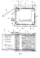
- the stacking machine comprises four successive trains of rollers, respectively referenced 1, 2, 3 and 4 and mounted one after the other by defining a rectangular profile and being separated by a free space suitably calculated in view of allowing the skins to be unloaded onto the stacking plate 5.
- Idler gear wheels 6, 7, 8 and 9 cooperate with an actuation chain 10 which ensures the movement of the aforementioned rollers and which is controlled by a electric motor 11 associated with a belt or chain transmission 12.
- Two small jacks 13 and 14 ensure, when desired, the immobilization of the transfer belts mounted on the four roller trains which are thus likely to advance by turning either in the opposite direction if one acted on the jack 13, or in the same direction if one acted on the jack 14.
- An inclined plane 15 pivotally mounted makes it possible to load the skins on the rollers during their advance. This inclined plane can however be eliminated when the loading is carried out by a machine arranged upstream or by a conveyor belt independent of the machine itself.
- FIG. 3 shows a first pair of rollers 1 mounted idly on support shafts 16 which are provided with toothed wheels 17 cooperating with a chain 18, while the transfer chain 19 is fixed on axes 20 provided projecting from the ends of the trees 16 above.
- rollers 1 are profiled so as to have projecting and depression parts which are alternated with respect to the adjacent rollers, in the manner shown in FIG. 3.
- these rollers can be hollowed out with grooves 21 which receive elastic rings 22, which form guides for the belts 23 which constitute the conveyor belt, it being observed that this can be constituted by a single element .
- the machine is provided double in order to be capable of carrying out the simultaneous loading of two stacking plates respectively referenced 24 and 25.
- the stacking system comprises in such a case six trains of rollers 26 and two pairs of jacks stop tires referenced 27 and 28 for the plate 24, 29 and 30 for the plate 25.
- the transfer ribbon provided at each train of rollers, it can take the form of a series of elementary ribbons 23 according to FIG. 4 as that of a single element which surrounds the rollers of each train. In this case, it is no longer necessary to rotate all the rollers; one can be content to train only the first, because the ribbons which are mounted on said rollers also serve to transmit movement to others.
- the subsequent train 2 If during this stacking phase the subsequent train 2 is left free, it will continue with the next skin until it comes in superposition on the plate 5 on which it will then unload the skin with the same orientation as the previous one. Under these conditions, the skins will overlap one another, all being oriented in the same way.
- each train of rollers ensures the constitution of a corresponding pile by skipping the preceding batteries and by operating in each stack a stacking in identical superposition or alternating, depending on the actuation of the stop cylinders 27, 28, 29 and 30.
- the speed of rotation of the elementary rollers can be identical to the speed of advance, but it can also be different by modifying the diameter of the pinions which join these elementary rollers.
- double-width machines can be produced, equipped with rollers which make it possible to simultaneously treat skins arranged side by side and intended to constitute two adjacent stacks.
- rollers of the four trains 31, 32, 33 and 34 are prevented from rotating by racks 35 and 36 which act alternately on one train of rollers or on another depending on the side where said rollers comprise the cogwheels.
- Another transfer mat 39 provided after the introduction conveyor 40, can be raised or lowered by a jack 41 by turning around a pivot 42, so as to allow a first skin to mount on the mat 39 when the latter is in the lowered position, while then this mat 39 is raised by actuating the jack 41 and, by reversing its direction of movement, causes the skin to rise on the train of rollers 31 surmounted by a second skin coming from always carpet 40, the skins being in such a case in contact flower against flower or flesh against flesh, or alternatively.
- the mat 39 is not used and remains in the raised position when the skins are to be stacked, all being oriented in the same direction.
- the machine according to the invention can be provided with detection means, for example photoelectric cells, to detect the arrival of a skin and start the ribbons which in this way stop when no skin to be stacked comes from previous operations, while when the skins are brought regularly to close distances, the whole remains in permanent operation without ever Stop.
- detection means for example photoelectric cells
Landscapes
- Engineering & Computer Science (AREA)
- Mechanical Engineering (AREA)
- Discharge By Other Means (AREA)
- Attitude Control For Articles On Conveyors (AREA)
Applications Claiming Priority (2)
| Application Number | Priority Date | Filing Date | Title |
|---|---|---|---|
| IT85605/85A IT1188030B (it) | 1985-10-16 | 1985-10-16 | Accatastatore di pelli rotativo |
| IT8560585 | 1985-10-16 |
Publications (2)
| Publication Number | Publication Date |
|---|---|
| EP0219108A2 true EP0219108A2 (de) | 1987-04-22 |
| EP0219108A3 EP0219108A3 (de) | 1988-10-05 |
Family
ID=11328846
Family Applications (1)
| Application Number | Title | Priority Date | Filing Date |
|---|---|---|---|
| EP86114253A Withdrawn EP0219108A3 (de) | 1985-10-16 | 1986-10-15 | Maschine des Rotationstyps zum Stapeln von Fellen |
Country Status (3)
| Country | Link |
|---|---|
| EP (1) | EP0219108A3 (de) |
| CS (1) | CS264339B2 (de) |
| IT (1) | IT1188030B (de) |
Cited By (3)
| Publication number | Priority date | Publication date | Assignee | Title |
|---|---|---|---|---|
| EP0568486A3 (de) * | 1992-05-01 | 1995-02-22 | Jensen Ejnar & Soen As | Vorrichtung zur wahlfreien Ablegung von Bogen u.dgl. |
| FR2861063A1 (fr) * | 2003-10-20 | 2005-04-22 | Techman Mecanisation Sa | Dispositif de manutention d'objets divers, notamment de materiaux en plaques ou en nappes |
| US8091390B2 (en) | 2006-08-16 | 2012-01-10 | Cargill, Incorporated | Hide folding system and method |
Family Cites Families (6)
| Publication number | Priority date | Publication date | Assignee | Title |
|---|---|---|---|---|
| US2323174A (en) * | 1939-03-08 | 1943-06-29 | Us Rubber Co | Apparatus for stacking sheet material |
| US2424761A (en) * | 1944-05-03 | 1947-07-29 | Roland I Kuffler | Stacking device |
| US2859965A (en) * | 1956-08-01 | 1958-11-11 | Alfa Machine Company Inc | Stackers and work delivery apparatus |
| DE1143758B (de) * | 1960-12-14 | 1963-02-14 | Trockentechnik G M B H | Vorrichtung zum Stapeln von flaechenfoermigen, biegsamen Stuecken |
| DE2438811A1 (de) * | 1974-08-13 | 1976-02-26 | Rudolf Grenzebach | Verfahren und vorrichtung zum wenden und paarweisen aufeinanderlegen von platten |
| GB1517518A (en) * | 1974-12-07 | 1978-07-12 | Simon Vicars Ltd | Dough laminators |
-
1985
- 1985-10-16 IT IT85605/85A patent/IT1188030B/it active
-
1986
- 1986-10-15 CS CS867470A patent/CS264339B2/cs unknown
- 1986-10-15 EP EP86114253A patent/EP0219108A3/de not_active Withdrawn
Cited By (3)
| Publication number | Priority date | Publication date | Assignee | Title |
|---|---|---|---|---|
| EP0568486A3 (de) * | 1992-05-01 | 1995-02-22 | Jensen Ejnar & Soen As | Vorrichtung zur wahlfreien Ablegung von Bogen u.dgl. |
| FR2861063A1 (fr) * | 2003-10-20 | 2005-04-22 | Techman Mecanisation Sa | Dispositif de manutention d'objets divers, notamment de materiaux en plaques ou en nappes |
| US8091390B2 (en) | 2006-08-16 | 2012-01-10 | Cargill, Incorporated | Hide folding system and method |
Also Published As
| Publication number | Publication date |
|---|---|
| EP0219108A3 (de) | 1988-10-05 |
| IT8585605A0 (it) | 1985-10-16 |
| CS747086A2 (en) | 1987-09-17 |
| CS264339B2 (en) | 1989-07-12 |
| IT1188030B (it) | 1987-12-30 |
Similar Documents
| Publication | Publication Date | Title |
|---|---|---|
| EP0503365B1 (de) | Angetriebener Kugeltisch zum orthogonalen Sortieren flacher Gegenstände | |
| EP0369133B1 (de) | Vorrichtung zum Transportieren und zur Orientierung von Bündeln flacher Gegenstände | |
| FR2540061A1 (fr) | Engin roulant tel notamment que siege pour handicape | |
| EP1369213B1 (de) | Vorrichtung zur Trennung Befestigungspunkte, die gestapelte Kartonbogen verbinden | |
| EP0543711B1 (de) | Brückenteil, insbesondere zur Überwindung von Gräben durch Fahrzeuge | |
| FR2732909A1 (fr) | Dispositif de selection de flans de carton decoupes | |
| EP0111432A1 (de) | Vorrichtung zur dynamischen Zwischenspeicherung flacher Gegenstände | |
| FR2726502A1 (fr) | Dispositif d'amenee d'une bande de papier a une plieuse d'une rotative d'impression a bobines | |
| WO2012146852A1 (fr) | Outil de manipulation et de regroupement de produits | |
| FR2488157A1 (fr) | Machine pour effectuer le brossage de toute la peripherie d'un objet circulaire substantiellement plat notamment d'une meule de fromage | |
| FR2557547A1 (fr) | Installation de fabrication a plusieurs postes fixes de travail et a dispositif de manutention | |
| EP1392531B1 (de) | Horizontalachsige maschine zum präsentieren von reifen | |
| FR2482067A1 (fr) | Appareil pour retourner une pile de feuilles | |
| EP0374194B1 (de) | Antriebssystem und anwendungsverfahren für auf einer schiene bewegbare wagen | |
| FR2529184A1 (fr) | Procede et appareil pour empiler des rubans | |
| FR2554094A2 (fr) | Dispositif d'empilage automatique notamment d'elements en plaque superposes a plat | |
| EP0152712B1 (de) | Verfahren zum Zusammensetzen einer Ladung aus horizontalen Säcken- oder Dosen-Schichten und Vorrichtung dazu | |
| EP0863096A1 (de) | Hebevorrichtung | |
| FR2619797A1 (fr) | Dispositif de transfert utilisable entre deux transporteurs sans fin | |
| WO1997043181A1 (fr) | Machine pour emballer des portions de produits dans un film de materiaux d'emballage | |
| CA1302335C (fr) | Systeme d'entrainement de chariots sur un rail et procede pour sa mise en oeuvre | |
| FR2613188A1 (fr) | Chargeur reversible pour chambres de fermentation et de prefermentation dans les industries du pain et analogues | |
| FR2636305A1 (fr) | Machine pour la fermeture de receptacles | |
| FR2527841A1 (fr) | Dispositif pour former des paquets d'electrodes pour generateurs electrochimiques | |
| EP0142433A1 (de) | Vorrichtung und Verfahren zum Stapeln von Winkeleisen |
Legal Events
| Date | Code | Title | Description |
|---|---|---|---|
| PUAI | Public reference made under article 153(3) epc to a published international application that has entered the european phase |
Free format text: ORIGINAL CODE: 0009012 |
|
| AK | Designated contracting states |
Kind code of ref document: A2 Designated state(s): AT BE CH DE ES FR GB GR IT LI LU NL SE |
|
| PUAL | Search report despatched |
Free format text: ORIGINAL CODE: 0009013 |
|
| AK | Designated contracting states |
Kind code of ref document: A3 Designated state(s): AT BE CH DE ES FR GB GR IT LI LU NL SE |
|
| STAA | Information on the status of an ep patent application or granted ep patent |
Free format text: STATUS: THE APPLICATION IS DEEMED TO BE WITHDRAWN |
|
| 18D | Application deemed to be withdrawn |
Effective date: 19890406 |
|
| RIN1 | Information on inventor provided before grant (corrected) |
Inventor name: BOSCHETTI, LUIGI |