EP0219126A2 - Installation de chauffage de liquide de lavage dans des dispositifs de lavage de vitres de véhicules - Google Patents
Installation de chauffage de liquide de lavage dans des dispositifs de lavage de vitres de véhicules Download PDFInfo
- Publication number
- EP0219126A2 EP0219126A2 EP86114340A EP86114340A EP0219126A2 EP 0219126 A2 EP0219126 A2 EP 0219126A2 EP 86114340 A EP86114340 A EP 86114340A EP 86114340 A EP86114340 A EP 86114340A EP 0219126 A2 EP0219126 A2 EP 0219126A2
- Authority
- EP
- European Patent Office
- Prior art keywords
- heating
- heating device
- support body
- temperature controller
- interior
- Prior art date
- Legal status (The legal status is an assumption and is not a legal conclusion. Google has not performed a legal analysis and makes no representation as to the accuracy of the status listed.)
- Withdrawn
Links
Images
Classifications
-
- B—PERFORMING OPERATIONS; TRANSPORTING
- B60—VEHICLES IN GENERAL
- B60S—SERVICING, CLEANING, REPAIRING, SUPPORTING, LIFTING, OR MANOEUVRING OF VEHICLES, NOT OTHERWISE PROVIDED FOR
- B60S1/00—Cleaning of vehicles
- B60S1/02—Cleaning windscreens, windows or optical devices
- B60S1/46—Cleaning windscreens, windows or optical devices using liquid; Windscreen washers
- B60S1/48—Liquid supply therefor
- B60S1/487—Liquid supply therefor the liquid being heated
- B60S1/488—Liquid supply therefor the liquid being heated electrically
Definitions
- the invention relates to a heating device for washing liquid in windshield washer systems of vehicles with an interior of a flow container, which is included in the liquid line, comprising a hollow body which is closed at both ends and has hose or pipe connections, and a strand-like heating element which is arranged in a starting from a power source, in particular a battery.
- a heating circuit containing a switching relay is provided, the interior being assigned a temperature-carrying device and connected to a control circuit connected to the switching relay.
- a wire coil is arranged in a housing tube which is closed at the end by housing cover, which is spaced apart from a bimetal switch, a reed contact or a temperature switch.
- the latter is connected on the one hand, for example, to the excitation terminal of an alternator and, on the other hand, to a switching relay with which a switch in the heating circuit is actuated.
- the temperature sensor may also be accommodated directly in the heating circuit, for example in the wire coil.
- the temperature sensor and the string-like heating element are both housed in the liquid flow space, which can lead to operating difficulties.
- Another heating device for washing liquids in windshield washer systems of vehicles offers DE-AS 26 27 402; a flow tank is placed around an exhaust manifold of the vehicle engine, which in turn is part of the wash water pipe and within which heat is exchanged from the exhaust pipe into the wash liquid.
- heating coils are arranged in the cooling water pipe, through which the washing water liquid reaches the spray nozzles.
- the inventor has set itself the goal of improving an electrically heatable device of the type mentioned at the outset in such a way that, with a sufficient energy balance for car batteries or the like, operational reliability is ensured even in the case of fully automatic operation, and in addition the heating device itself is small in size so that it can be easily accommodated in the vehicle. In addition, this heater is also intended to retrofit older vehicles.
- the hollow body is provided at least on one surface with a heat-conducting, electrically insulating layer and the heating wire, a heating tape or the like is wound around this supporting body, that the heating wire or the like is a protective sleeve parallel to the supporting body surrounds, which has at least on its inside an electrically insulating and heat-conducting layer, a temperature controller being fixed as a temperature-sensing device near the interior and outside of it on the support body.
- the supporting body and / or the protective sleeve from light metal, which has been subjected to an anodizing process;
- the anodizing layer formed on the light metal during anodizing offers all the requirements that are required of the thermally conductive or at least non-thermal insulating and electrically insulating layer.
- carrier body / insulating layer or protective sleeve / insulating layer are also possible, for example ceramic bodies with a PJasmas layer or metal bodies with a thermally sprayed plastic layer or a thin ceramic layer - in preferred embodiments, layers of aluminum oxide or at least partially stabilized zirconium oxide.
- a helical groove lined with that anodized layer, in which the heating wire is embedded is introduced into the outer surface of the supporting body in such a way that a Part of its circumference touches the groove wall.
- the heating wire - or the heating tape - should be glued to the support body - if necessary also to the protective sleeve.
- the support body as an annular wall with a base that closes off the ends thereof, the annular wall at its other end being releasably and tightly connected to an end cover, preferably with the interposition of an O-ring.
- the switch-off temperature is 75 ° C for a temperature at the spray nozzle of 80 ° C.
- This temperature controller is preferably connected on the one hand to the control cable and on the other hand to the negative pole of the battery.
- a deflecting baffle can even be, for example, a line which continues the inlet connection for the liquid and leads to the inner surface of the support body, which also produces a swirling of the water.
- the pipe connections are integrated coaxially into the base and the end cover] and that there are holders for the heating circuit connection bracket and control cable connection tabs, the heating wire or heating tape being connected to those connection brackets.
- the connecting bows] and connecting tongue (s) should sit on a common pipe connection, from which they are electrically insulated by an insulating layer of the pipe connection with the interposition of radially pushed-on insulating washers.
- Unwanted overheating is prevented by installing a fuse or a corresponding fuse element that responds at about 180 ° C., which is arranged between the connecting bracket of the heating current cable on the one hand and the heating wire, heating tape or the like on the other hand.
- a switch is provided in the heating circuit as part of the switching relay, which is inserted into the control line between the alternator and the temperature controller.
- it is intended to be on-off Install a switch between the alternator and switching relay to be able to interrupt the entire facility.
- the support body described is wrapped according to the invention with the heating wire or heating tape and then firmly connected to the pushed-on protective sleeve - these elements, together with the connecting brackets and connecting tongues which are plugged onto the pipe connections and fixed there, form a structural unit which, within the scope of the invention, is pushed into a housing
- the latter consists of a pipe wall closed on both ends by end walls, which is penetrated by the pipe connections and the connecting bends or connecting tongues; the installation unit hangs on the pipe connections in the end walls of this housing and thus at a distance from the inside of the pipe wall, which further increases the desired effects.
- a plastic body preferably made of solvent-free epoxy resin with hardener or. Made of cross-linked inorganic / organic polymer with hardener to cast that protective sleeve.
- the heating device draws in the required voltage via the alternator, and at the same time the heating current is released by the battery via the switching relay.
- the built-in temperature controller switches off the power supply via the switching relay, a process that is constantly repeated.
- the heating time is only about 25 seconds at 400 to 570 watts of power in order to achieve a windshield water temperature of 80 ° C. This guarantees a quick and safe heating of the wash water.
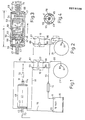
- FIG. 1 shows a heating circuit of a motor vehicle (not shown for reasons of clarity) with a battery 10, from whose poles 11 (plus) or 13 - including a fuse 14 - heating current cables 15 and 16 emanate.
- BankstromkabeJ 16 leads to a heater 40 and leaves it as a heating cable 16 f .
- a switching tongue 17 can be seen between its other contact end 87 and that of the heating current cable 15. The latter is actuated in a relay indicated at 18, which is connected at 86 on the one hand to a control line 19 - likewise leading to the heating device 40, at 85 on the other hand by means of a line 20 to an alternator 21 in order to rapidly discharge the battery 10 prevent.
- the alternator 21 is located at 61 connected line 20, an additional switch 22, thanks to which the entire reproduced current flow can be interrupted.
- a resistor can be inserted in an insulated manner in the line 20, which ensures that the relay 18 does not pick up as long as the alternator 21 emits a current or as long as the charging control lamp of the motor vehicle is not lit.
- the heating device 40 has a cylindrical tube wall 41, which is supplemented by disk-shaped end walls 43 to form a protective housing. From this protrude to the central axis M of the pipe wall 41 coaxial pipe connections 45 and 45 passing through the end walls 43 for water hoses indicated at 70.
- a supporting body 50 consisting of base 51 and integrally formed ring wall 52 is coaxially supported in the protective housing made of tube wall 41 and end walls 43, and an end cover 55 is placed on the tube opening 53 with the interposition of a temperature-resistant 0-ring 54.
- connecting bows 56 and 57 for the heating current cables 16, 16 f - and a connecting tongue (76 in FIG. 5) for the control line 19 - are fixed.
- a heating tape 59 is wound onto the connection bracket 56, 57 and is glued thereon, a protective sleeve 60 is pushed onto the latter.
- a temperature controller 63 with a temperature switch 66 is introduced into a transverse bore 64 of the base 51 and .with the connecting bracket 76 for the control cable 19 and the connecting bracket 56 for the negative pole 13 conductively connected. With 65 a safety bridge is designated, which ensures a power interruption at 180 ° C between heating tape 59 and bracket 57.
- a temperature-resistant water hose 70 For commissioning, the end of a temperature-resistant water hose 70 is pushed onto each of the pipe connections 45, 45 e and secured with a hose clamp (not shown).
- the left-hand water hose 70 in FIG. 1 connects to a feed pump, not shown in the drawing, of a container for a windshield washer fluid, the other water hose 70 leads to the spray nozzle of the motor vehicle wiper system (PfeiJ x).
- the interior 49 of the support body 50 is integrated thanks to axial openings 58 in the base 51 and in the end cover 55 in the water circuit as a flow container space.
- at least one guide disk 67 with an eccentric through hole 68 arranged near the temperature controller 63 is fixed radially to the central axis M, which forces the washing liquid entering through the pipe connection 45 to the base containing the temperature controller 63 and with the through hole 68 a swirl generated.
- An edge collar 67 n of the guide pulley 67 lies firmly against the inside of the support body 50 and thus allows simple assembly by insertion.
- the heating device 40 draws the required voltage via the alternator 21 and is put into operation.
- the heating current is released by the battery 10 via that switching relay 18.
- the temperature controller 63 which adjusts to the operation of the windshield washer system and the ambient temperature, switches off the power supply again via the relay 18, with short heating-up times being sufficient. The process is repeated again and again depending on the amount of liquid required.
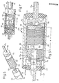
- the heating tape 59 is replaced by a heating wire 69, which is also wound on a support body 50 a ; the latter has, on its outer surface, a holding groove 22 which runs like a screw thread for receiving the heating wire 69.
- the length a of the winding of the heating wire 69 is performance-dependent and also determines the length of the protective sleeve 60, near whose obliquely cut end edge 62 a connection 73 for the connecting bracket 56 and heating wire 69 rests.
- This connection bracket 56 is separated from the base 51 by an insulating washer 75.
- Another IsoJierinstallation 75 is mounted between the connecting bracket 56 for the one heating current cable 16 and the connecting tongue 76 between the control line 19 and temperature control element 63. With the interposition of an Isoller disk 57, this connecting tongue 76 follows the connecting bracket 57 for the heating current cable 16 f .
- a spring ring is designated, which holds the package of insulating washers 75 and electrical connecting elements 56, 57, 76 on the non-conductive pipe connection 45.
- Such a spring ring 77 also sits on the other pipe connection 45, where an intermediate conductor 74 connected to the heating wire 69 and a conductive U-piece 78 connected to it by the fuse bridge 65 made of fuse wire are stored between the insulating disks 75.
- the end of the U-piece 78 which is distant from the securing bridge 65, is soldered to a conductor strip 79 which, at the other end, lies firmly against the connecting bracket 57.
- Both the support body 50 and the protective sleeve 60 consist of anodized aluminum; the very thin anodized layer is no obstacle to heat dissipation, but prevents a breakdown of current to the liquid.
- the tube wall 41 Due to the small dimensions of the tube wall 41 (length b about 90 mm with a diameter d of 35 mm) and a low installation weight of the heating device 40 of about 160 grams, a suitable installation location for the heating device 40 can easily be found on the vehicle. In order to avoid unnecessary heat losses, this should be inserted as close as possible to the spray nozzles in their hose line 70. It has proven particularly favorable to provide a heating device 40 on each spray nozzle.
- the heating device 40 works as a continuous-flow heater for washing liquid which then flows continuously through the interior 49.
- the spray nozzles are only actuated for short periods of approximately 1 second each, the spray phases being shorter than the spray pauses.
- the spray nozzles are actuated in pulses, a higher temperature is reached than when the continuous operation is continued.
- the excitation terminal 61 of the control line 19 is at the required voltage to put the heater into operation; the switching relay 18 picks up and switches on the electrical heating current. If the washing liquid has reached a sufficiently high temperature, the temperature controller 63 or the temperature switch 66 close to the liquid flow interrupts the control current, the relay 18 drops out, and the heating current is interrupted.
- the current required is around 48 amps.
- the shutdown temperature of about 75 ° is reached. If the heating device 40 passes through cold washing liquid when the spray nozzle is actuated, the heater is immediately reheated. The washing liquid is therefore always kept at a sufficiently high temperature.
- the heating device 40 is also switched off by switching off the engine. If the temperature controller 63 is defective or the relay 18 is stuck, the fuse bridge 65 ensures a power interruption.
- the heating power of the preferred embodiment is between 400 watts and 570 watts.
- the protective sleeve 60 and the device parts protruding therefrom are cast into an impact-resistant plastic sleeve 81 with a cylindrical outer surface 82.
- the material for this is a solvent-free, low-viscosity epoxy resin with a low-viscosity polyamine hardener and is characterized by a low initial viscosity, good thermal and chemical resistance and low susceptibility to cracking.
- the Shore hardness D in the selected embodiment is approximately 25, the dielectric constant (50 Hz; 50 ° C.) approximately 8.5 and the dielectric strength (20 s value) between 200 and 250 kV / cm.
- the density of the plastic casing 81 is between 0.1 and 0.4 g / cm 3 .
- Crosslinked inorganic / organic polymers of a two-component system preferably used here a mixture of about 100 parts by weight of resin with about 30 parts by weight of hardener and a curing time of about six hours, are suitable for use at temperatures up to about 375 ° C.
- an elastic, non-flammable, very light insulating foam with a fine-pored, cellular structure is used in other versions, which is free of organic binders. Its melting point is around 1500 ° C, its thermal conductivity (in W / mK) at 350 ° C is 0.105.
- This material is water-repellent, without capillary absorbency and seawater and oil resistant.
Landscapes
- Engineering & Computer Science (AREA)
- Water Supply & Treatment (AREA)
- Mechanical Engineering (AREA)
- Instantaneous Water Boilers, Portable Hot-Water Supply Apparatuses, And Control Of Portable Hot-Water Supply Apparatuses (AREA)
- Surface Heating Bodies (AREA)
- Resistance Heating (AREA)
Applications Claiming Priority (2)
| Application Number | Priority Date | Filing Date | Title |
|---|---|---|---|
| DE19853536751 DE3536751A1 (de) | 1985-10-15 | 1985-10-15 | Heizvorrichtung fuer waschfluessigkeit in scheibenwaschanlagen von fahrzeugen |
| DE3536751 | 1985-10-15 |
Publications (2)
| Publication Number | Publication Date |
|---|---|
| EP0219126A2 true EP0219126A2 (fr) | 1987-04-22 |
| EP0219126A3 EP0219126A3 (fr) | 1988-03-16 |
Family
ID=6283623
Family Applications (1)
| Application Number | Title | Priority Date | Filing Date |
|---|---|---|---|
| EP86114340A Withdrawn EP0219126A3 (fr) | 1985-10-15 | 1986-10-15 | Installation de chauffage de liquide de lavage dans des dispositifs de lavage de vitres de véhicules |
Country Status (2)
| Country | Link |
|---|---|
| EP (1) | EP0219126A3 (fr) |
| DE (1) | DE3536751A1 (fr) |
Cited By (14)
| Publication number | Priority date | Publication date | Assignee | Title |
|---|---|---|---|---|
| FR2707230A1 (fr) * | 1993-07-07 | 1995-01-13 | Cornet Andre | Dispositif réchauffeur rapide de liquide de lave-glace pour le dégivrage et le nettoyage des pare-brises des véhicules automobiles. |
| WO2005023609A2 (fr) | 2003-09-03 | 2005-03-17 | Nartron Corporation | Systeme de nettoyage pour pare-brise |
| US7588194B2 (en) | 2003-09-03 | 2009-09-15 | Sbr Investments Company Llc | Vehicle windshield cleaning system |
| US7657961B2 (en) | 2002-10-02 | 2010-02-09 | Sbr Investments Company Llc | Vehicle windshield cleaning system |
| WO2010057819A1 (fr) * | 2008-11-18 | 2010-05-27 | Voss Automotive Gmbh | Raccord de conduite pour conduites de fluides |
| US7857238B2 (en) | 2002-10-02 | 2010-12-28 | Sbr Investments Company Llc | Vehicle windshield cleaning system |
| US8157187B2 (en) | 2002-10-02 | 2012-04-17 | Sbr Investments Company Llc | Vehicle windshield cleaning system |
| EP1622798A4 (fr) * | 2003-02-28 | 2014-11-12 | Valeo Electrical Sys Inc | Appareil et methode de commande de temperature de dispositif de chauffage fluidique |
| US9429259B2 (en) | 2007-04-26 | 2016-08-30 | Voss Automotive Gmbh | Line connector for media lines |
| US9651185B2 (en) | 2008-03-19 | 2017-05-16 | Voss Automotive Gmbh | Line connector for media lines |
| US9890889B2 (en) | 2007-12-21 | 2018-02-13 | Voss Automotive Gmbh | Line connector and ready-made media line |
| EP1985908B2 (fr) † | 2007-04-26 | 2018-09-19 | Voss Automotive GmbH | Liaison câblée pour tansfer de fluides |
| US10384653B2 (en) | 2004-03-09 | 2019-08-20 | Uusi, Llc | Vehicle windshield cleaning system |
| US11332101B2 (en) | 2004-03-09 | 2022-05-17 | Uusi, Llc | Vehicle windshield cleaning system |
Families Citing this family (1)
| Publication number | Priority date | Publication date | Assignee | Title |
|---|---|---|---|---|
| SE0401557D0 (sv) * | 2004-06-15 | 2004-06-15 | Volvo Lastvagnar Ab | Elektrisk uppvärmningsbart kopplingsstycke samt inkapslad vätskeslang med elektriskt uppvärmningsbart kopplingsstycke |
Family Cites Families (13)
| Publication number | Priority date | Publication date | Assignee | Title |
|---|---|---|---|---|
| FR531068A (fr) * | 1921-02-16 | 1922-01-06 | Appareils Manutention Fours Stein Sa | Dispositif de chauffage électrique des combustibles liquides |
| US2519920A (en) * | 1947-07-10 | 1950-08-22 | Donald B Miner | Electric resistance water heater |
| AT238841B (de) * | 1960-02-10 | 1965-03-10 | Siemens Elektrogeraete Gmbh | Elektrischer Durchlauferhitzer |
| US3120600A (en) * | 1962-07-02 | 1964-02-04 | Cecil W True | Freezeless water supply |
| US3378673A (en) * | 1965-10-18 | 1968-04-16 | Thomas O. Hopper | Electrically heated hose assembly |
| DE1806721A1 (de) * | 1968-11-02 | 1970-05-21 | Siemens Elektrogeraete Gmbh | Elektrischer Durchlauferhitzer |
| CA937474A (en) * | 1971-06-30 | 1973-11-27 | Bardon Research And Development Limited | Engine preheater |
| DE2555841A1 (de) * | 1975-12-11 | 1977-06-23 | Lorenz Moser | Vorrichtung zum enteisen von fahrzeugsichtscheiben |
| US4090668A (en) * | 1976-12-06 | 1978-05-23 | Kochenour Paul R | Windshield washer and deicer |
| DE3149623A1 (de) * | 1981-12-15 | 1983-07-21 | Joachim Pfaus | Schlauch fuer eine in einem fahrzeug angeordnete waschanlage |
| DE3221348A1 (de) * | 1982-06-05 | 1983-12-08 | E.G.O. Elektro-Geräte Blanc u. Fischer, 7519 Oberderdingen | Heizelement mit zylindrischer wandung |
| DE3307962A1 (de) * | 1983-03-07 | 1984-09-20 | Siemens AG, 1000 Berlin und 8000 München | Elektrischer durchlauferhitzer fuer getraenkebereiter |
| DE3324120A1 (de) * | 1983-07-05 | 1985-01-17 | Wetzig, Petra, 7148 Remseck | Heizgeraet fuer das erhitzen der waschfluessigkeit von scheibenwaschanlgen von fahrzeugen |
-
1985
- 1985-10-15 DE DE19853536751 patent/DE3536751A1/de not_active Withdrawn
-
1986
- 1986-10-15 EP EP86114340A patent/EP0219126A3/fr not_active Withdrawn
Cited By (23)
| Publication number | Priority date | Publication date | Assignee | Title |
|---|---|---|---|---|
| FR2707230A1 (fr) * | 1993-07-07 | 1995-01-13 | Cornet Andre | Dispositif réchauffeur rapide de liquide de lave-glace pour le dégivrage et le nettoyage des pare-brises des véhicules automobiles. |
| US8141794B2 (en) | 2002-10-02 | 2012-03-27 | Sbr Investments Company Llc | Vehicle windshield cleaning system |
| US7857238B2 (en) | 2002-10-02 | 2010-12-28 | Sbr Investments Company Llc | Vehicle windshield cleaning system |
| US8157187B2 (en) | 2002-10-02 | 2012-04-17 | Sbr Investments Company Llc | Vehicle windshield cleaning system |
| US7641131B2 (en) | 2002-10-02 | 2010-01-05 | Sbr Investments Company Llc | Vehicle windshield cleaning system |
| US7657961B2 (en) | 2002-10-02 | 2010-02-09 | Sbr Investments Company Llc | Vehicle windshield cleaning system |
| US7673814B2 (en) | 2002-10-02 | 2010-03-09 | Sbr Investments Company Llc | Vehicle windshield cleaning system |
| US8123148B2 (en) | 2002-10-02 | 2012-02-28 | Sbr Investments Company Llc | Vehicle windshield cleaning system |
| EP1622798A4 (fr) * | 2003-02-28 | 2014-11-12 | Valeo Electrical Sys Inc | Appareil et methode de commande de temperature de dispositif de chauffage fluidique |
| EP1667800A4 (fr) * | 2003-09-03 | 2006-12-13 | Sbt Invest Company Llc | Systeme de nettoyage pour pare-brise |
| US8505832B2 (en) | 2003-09-03 | 2013-08-13 | Uusi, Llc | Vehicle windshield cleaning system |
| WO2005023609A2 (fr) | 2003-09-03 | 2005-03-17 | Nartron Corporation | Systeme de nettoyage pour pare-brise |
| US7588194B2 (en) | 2003-09-03 | 2009-09-15 | Sbr Investments Company Llc | Vehicle windshield cleaning system |
| US11332101B2 (en) | 2004-03-09 | 2022-05-17 | Uusi, Llc | Vehicle windshield cleaning system |
| US10384653B2 (en) | 2004-03-09 | 2019-08-20 | Uusi, Llc | Vehicle windshield cleaning system |
| US9188268B2 (en) | 2004-03-09 | 2015-11-17 | Uusi, Llc | Vehicle windshield cleaning system |
| EP2137449B2 (fr) † | 2007-04-26 | 2018-10-17 | Voss Automotive GmbH | Raccord pour conduites d'acheminement de substances |
| US9429259B2 (en) | 2007-04-26 | 2016-08-30 | Voss Automotive Gmbh | Line connector for media lines |
| EP1985908B2 (fr) † | 2007-04-26 | 2018-09-19 | Voss Automotive GmbH | Liaison câblée pour tansfer de fluides |
| US9890889B2 (en) | 2007-12-21 | 2018-02-13 | Voss Automotive Gmbh | Line connector and ready-made media line |
| US9651185B2 (en) | 2008-03-19 | 2017-05-16 | Voss Automotive Gmbh | Line connector for media lines |
| US8921744B2 (en) | 2008-11-18 | 2014-12-30 | Voss Automotive Gmbh | Line connector for media lines |
| WO2010057819A1 (fr) * | 2008-11-18 | 2010-05-27 | Voss Automotive Gmbh | Raccord de conduite pour conduites de fluides |
Also Published As
| Publication number | Publication date |
|---|---|
| DE3536751A1 (de) | 1987-04-16 |
| EP0219126A3 (fr) | 1988-03-16 |
Similar Documents
| Publication | Publication Date | Title |
|---|---|---|
| DE102007005771B4 (de) | Filtereinrichtung, insbesondere Flüssigkeitsfilter, mit einer Heizung | |
| DE3536751A1 (de) | Heizvorrichtung fuer waschfluessigkeit in scheibenwaschanlagen von fahrzeugen | |
| EP2137449B2 (fr) | Raccord pour conduites d'acheminement de substances | |
| DE69827130T2 (de) | Enteisung von windschutzscheiben | |
| EP0086465B1 (fr) | Corps de chauffe tubulaire muni d'un coupe-circuit de surcharge | |
| DE3002232A1 (de) | Schalteinrichtung fuer elektrische andrehvorrichtungen fuer brennkraftmaschinen | |
| DE8715851U1 (de) | Rohrheizkörper mit einer Überlastungssicherung | |
| WO2002016763A1 (fr) | Systeme de demarrage electrique pour moteurs a combustion interne avec protection contre les surcharges | |
| DE3709308A1 (de) | Elektrische heizvorrichtung fuer waschfluessigkeit in scheibenwaschanlagen von fahrzeugen | |
| DE3217758A1 (de) | Zusatzeinrichtung am kuehlwasserkreislauf von kraftfahrzeugmotoren | |
| EP0008478A1 (fr) | Sèche-cheveux et procédé de fabrication d'un élément chauffant pour ce sèche-cheveux | |
| EP0593724B1 (fr) | Raccord de buse pour bruleur a pulverisation de fuel sous pression | |
| DE19950956A1 (de) | Elektrischer Speisestromkreis eines Anlassermotors und Kraftfahrzeuganlasser mit integrierter Sicherung und zugehöriger Anlasser | |
| EP0240832A1 (fr) | Dispositif de réchauffage électrique du liquide de lave-glace d'un véhicule | |
| US3402280A (en) | Starter solenoid with electrical heating means | |
| DE19859011C1 (de) | Elektromotor | |
| DE3734961A1 (de) | Heizvorrichtung fuer waschfluessigkeit in scheibenwaschanlagen von fahrzeugen | |
| DE3324120C2 (fr) | ||
| DE2137285B2 (de) | Selbsttätige Sicherheitsschaltung zur Überwachung des Leistungsschaltgliedes eines elektrischen Stromverbrauchers | |
| EP0876081B1 (fr) | Elément de chauffage tubulaire incorporant une protection contre une surchauffe | |
| DE102016113863A1 (de) | Additivbehälter für ein SCR-System | |
| DE917924C (de) | Elektrischer Heizkoerper | |
| DE2909219A1 (de) | Temperaturabhaengig geschaltete auftau- und frostsicherungseinrichtung fuer scheibenwaschanlagen | |
| DE823733C (de) | Stromzuleitungshalter, insbesondere fuer elektrische Buegeleisen | |
| US1754580A (en) | Electric water heater |
Legal Events
| Date | Code | Title | Description |
|---|---|---|---|
| PUAI | Public reference made under article 153(3) epc to a published international application that has entered the european phase |
Free format text: ORIGINAL CODE: 0009012 |
|
| AK | Designated contracting states |
Kind code of ref document: A2 Designated state(s): AT BE CH DE ES FR GB GR IT LI LU NL SE |
|
| RBV | Designated contracting states (corrected) |
Designated state(s): AT CH DE FR GB IT LI SE |
|
| PUAL | Search report despatched |
Free format text: ORIGINAL CODE: 0009013 |
|
| AK | Designated contracting states |
Kind code of ref document: A3 Designated state(s): AT CH DE FR GB IT LI SE |
|
| STAA | Information on the status of an ep patent application or granted ep patent |
Free format text: STATUS: THE APPLICATION IS DEEMED TO BE WITHDRAWN |
|
| 18D | Application deemed to be withdrawn |
Effective date: 19880917 |
|
| RIN1 | Information on inventor provided before grant (corrected) |
Inventor name: SCHEIBE, WOLFGANG, DR. Inventor name: VON ZABERN, WERNER |