EP0219212A1 - Verfahren zur Verringerung des Quantisierungsfehlers für Phasenmodulationsgradient bei KMR-Abbildung - Google Patents
Verfahren zur Verringerung des Quantisierungsfehlers für Phasenmodulationsgradient bei KMR-Abbildung Download PDFInfo
- Publication number
- EP0219212A1 EP0219212A1 EP86306665A EP86306665A EP0219212A1 EP 0219212 A1 EP0219212 A1 EP 0219212A1 EP 86306665 A EP86306665 A EP 86306665A EP 86306665 A EP86306665 A EP 86306665A EP 0219212 A1 EP0219212 A1 EP 0219212A1
- Authority
- EP
- European Patent Office
- Prior art keywords
- waveform
- area
- phase encode
- gradient
- quantization error
- Prior art date
- Legal status (The legal status is an assumption and is not a legal conclusion. Google has not performed a legal analysis and makes no representation as to the accuracy of the status listed.)
- Granted
Links
- 238000013139 quantization Methods 0.000 title claims abstract description 40
- 238000003384 imaging method Methods 0.000 title claims abstract description 19
- 238000000034 method Methods 0.000 title claims description 50
- 230000009467 reduction Effects 0.000 title description 4
- 230000005284 excitation Effects 0.000 claims abstract description 7
- 230000007704 transition Effects 0.000 claims description 29
- 238000005481 NMR spectroscopy Methods 0.000 claims description 23
- 238000000264 spin echo pulse sequence Methods 0.000 claims description 8
- 230000006870 function Effects 0.000 claims description 7
- 239000011159 matrix material Substances 0.000 claims description 4
- 238000004458 analytical method Methods 0.000 claims description 3
- 230000000694 effects Effects 0.000 description 10
- 230000008569 process Effects 0.000 description 6
- 230000008859 change Effects 0.000 description 5
- 230000015654 memory Effects 0.000 description 4
- 238000010586 diagram Methods 0.000 description 3
- 229920005994 diacetyl cellulose Polymers 0.000 description 2
- 238000007689 inspection Methods 0.000 description 2
- 238000005070 sampling Methods 0.000 description 2
- UFHFLCQGNIYNRP-UHFFFAOYSA-N Hydrogen Chemical compound [H][H] UFHFLCQGNIYNRP-UHFFFAOYSA-N 0.000 description 1
- 238000002583 angiography Methods 0.000 description 1
- 230000008901 benefit Effects 0.000 description 1
- 238000006243 chemical reaction Methods 0.000 description 1
- 230000009977 dual effect Effects 0.000 description 1
- 229910052739 hydrogen Inorganic materials 0.000 description 1
- 239000001257 hydrogen Substances 0.000 description 1
- 230000006698 induction Effects 0.000 description 1
- 230000010287 polarization Effects 0.000 description 1
- 230000003068 static effect Effects 0.000 description 1
Images



Classifications
-
- G—PHYSICS
- G01—MEASURING; TESTING
- G01R—MEASURING ELECTRIC VARIABLES; MEASURING MAGNETIC VARIABLES
- G01R33/00—Arrangements or instruments for measuring magnetic variables
- G01R33/20—Arrangements or instruments for measuring magnetic variables involving magnetic resonance
- G01R33/44—Arrangements or instruments for measuring magnetic variables involving magnetic resonance using nuclear magnetic resonance [NMR]
- G01R33/48—NMR imaging systems
- G01R33/4818—MR characterised by data acquisition along a specific k-space trajectory or by the temporal order of k-space coverage, e.g. centric or segmented coverage of k-space
- G01R33/482—MR characterised by data acquisition along a specific k-space trajectory or by the temporal order of k-space coverage, e.g. centric or segmented coverage of k-space using a Cartesian trajectory
Definitions
- This invention relates to an imaging method for nuclear magnetic resonance (NMR), and more particularly to a process for correcting the quantization error of a phase encode gradient waveform.
- NMR nuclear magnetic resonance
- Such digital to analog conversion inherently involves a quantization error.
- the values of, for example, the phase encoding waveform amplitude must be rounded off to the nearest digital to analog converter (DAC) value.
- DAC digital to analog converter
- another solution is merely providing digital to analog converters with higher resolution; for example, 16 bit DACs versus 12 bit DACs.
- such converters must be high speed, glitch-free and have extremely good linearity; such converters are expensive.
- a method for a nuclear magnetic resonance (NMR) imaging apparatus having gradient coils driven by gradient waveforms.
- the gradient waveforms are produced by digital to analog converters having a predetermined quantization error.
- a phase encode waveform for providing an image of a subject.
- Such waveform by a variation of its area, provides a parameter to spatially encode the image.
- the method comprises steps of: (1) determining desired areas for the phase encode waveform; (2) a theoretical area error is determined from the desired areas due to the quantization error; (3) a first phase encode waveform is provided having a rounded-off area relative to the desired area; (4) at least one additional phase encode waveform is provided which is in the same spin-echo sequence as the first phase encode waveform, the additional waveform having an area substantially equal to the area error, the additional waveform being substantially smaller in area than the first waveform.
- the method includes the foregoing method as defined above in the preamble and includes the step of, in the same spin-echo sequence, providing at least one phase encode waveform having amplitudes to avoid the quantization error and then the step of varying the effective area of the phase encode waveform in the spin-echo sequence through a predetermined plurality of discrete increments while still maintaining the quantization error avoiding amplitudes.
- One more specific technique in accordance with the invention includes the steps of providing at least one phase encode waveform having fixed maximum positive and negative polarity amplitudes with a transition through a zero level, the location and time of the transition determining the area of the phase encode waveform. Then the area of the phase encode waveform is varied in a plurality of discrete phase encoding steps by changing the location in time of the transition.
- Fig. 1 illustrates an NMR system which in its block diagram form is of a standard type. However, with the process of the present invention , it is possible to utilize the improved method.
- the main magnet 10 provides a magnetic field Bo which generates a static magnetic field realizing a polarization of the nuclei of the subject.
- Within magnet 10 therefore is a cavity or space in which the specimen or human to be examined is placed.
- the apparatus also includes a gradient system utilized for producing spatial linear field gradients. These gradient fields are conventially established by the use of a set of three orthogonal direct current coils which generate the three principal gradients, G'x, G'y and G'z. The coils themselves are numbered 11 through 13, and are driven by a gradient generator 14, which in turn is controlled by a controller 16 which communicates with a host computer 20.
- the third component of the typical NMR system includes the radio frequency (RF) coil 17, which generates radio frequency fields in the subject being analyzed and picks up the free induction decay or spin-echo signal which is generated after termination of the radio frequency pulse.
- RF coil 17 For exciting RF coil 17 there is an RF pulse unit 18.
- the signal processor 19 receives the small microvoltage level spin echo signals generated by the subject and these are processed by computer 20 to form an image.
- the image is digitized in an analog to digital converter and stored in the memory section of computer 20 for later display by means of a display 21 which may typically be a cathode ray tube.
- This reconstructed image on a cathode ray tube has a resolution determined by the number of pixels (for example, 128 or 256) across each horizontal scan line of the CRT.
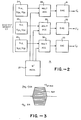
- Fig. 2 shows the circuit and details of the gradient generator 14 for generating the gradient waveforms for driving the three coils 11, 13 and 14. It includes a dual port memory 23, which includes individual orthogonal gradient memories 24, 25 and 26 corresponding to G'x, G'y and G'z, respectively.
- 3 gradient waveforms for each axis are stored in memory 23 which have been calibrated and compensated for each individual axis.
- equations 4, 5 and 6 define these various orthogonal gradients as relating to a readout gradient, a phase encode gradient and a slice select gradient. These waveforms are also illustrated in Figs. 4B, 4C and 4D.
- the present invention modifies in one embodiment, as will be explained below, the "M'" values related to the phase encode gradient. Specifically, these are M' 12 " M' 22 ' and M' 32 .
- the multiplier accumulators 28, 29 and 30 multiply the various gradient functions by the proper "M"' values and the digital numbers are converted in the associated digital to analog converters 31, 32 and 33 to form the actual gradient waveforms which are applied, as currents, to their respective gradient coils as illustrated in Fig. 1.
- the digital to analog converters have a 12 bit resolution. And as discussed they create a definite quantization error.
- Fig. 4A shows a typical RF pulse and excitation signals for 90° and 180° with a time interval between the two signals of tau ( ⁇ ).
- three basic waveforms may be needed: These might be the slice select waveform of Fig. 4B; the phase encoding waveform of Fig. 4C, and the read out waveform of Fig. 4D.
- the spin echo signal occurs at a time two tau (2 T ) after the 90° excitation pulse.
- the spin echo signal produces one line of data and the sequence shown in Fig. 4 can be defined as a spinecho sequence.
- Fig. 2 The overall operation of the invention is illustrated in Fig. 2 where the primes applied to the gradient waveforms G' , G' and G' indicate a rotated set of z axes or coordinates.
- the rotation matrix coefficients "M" and their relationships with the angles phi, theta and omega, which are defined in the copending application are shown in equations 10 through 18.
- K the various "M” factors are actually multiplied or adjusted by various "K” factors.
- K the SS slice select strength, determines the thickness of the selected slice being imaged
- K ph and K ro the resolution.
- the present invention in one embodiment, specifically concerns the adjustment of Kp h o
- Basic matrix "M" values must be considered for each set of theta and phi values. This can be done by computer 20 or other manual controls. For convenience, the same conventions could be used here as in conventional X-ray angiography.
- Fig. 3 illustrates a typical phase encode gradient waveform. It illustrates how variation of its area provides a parameter to determine the pixels of the final image.
- N points of a spin echo are acquired at a sampling interval of 6t. This is repeated for "N" values of the phase encoding gradient (from negative maximum of the gradient to the positive maximum as shown in Fig. 3). This gives N 2 sample points which are reconstructed into an NxN image by using a two-dimensional Fourier transform. The size of the pixel, ⁇ x, in the reconstructed image is determined as discussed above by both the readout gradient and the phase encode gradient.
- gamma (y) is the gyromagnetic constant (42.57MHz/Tesla for Hydrogen); N number of pixels across the final image; At - sampling interval in seconds; and Gro readout gradient strength (Gauss/cm).
- the Kro factor is adjusted, as shown in equations 7, 8 and 9, to provide the proper resolution.
- the same resolution is desired in the phase encoding direction. This resolution is determined by the gyromagnetic constant, and the total area of the phase encoding pulse, as shown in equation 20. Ap h is determined by, of course, integrating the area under the pulse.
- the area of the phase encoding pulse is stepped through the values as shown in equation 21, and as illustrated in Fig. 3.
- Equation 22 defines AA.
- the area of the phase encoding gradient waveform is of prime importance in the NMR imaging process. This concept is utilized to reduce the effect of quantization errors as illustrated by the improved phase encoding waveform of Fig. 4F.
- the phase encoding pulse is broken into two areas, one being substantially smaller than the other. The second, however, has the same height for purposes of data manipulation as will be clear below.
- the ratio of the two areas has been made equal to 25.
- the effective resolution (approximately 4-1/2 bits) of the phase encoding pulse is increased by this factor R (see equation 35).
- the height of these two pulses are controlled independently as illustrated in Fig. 4G, by using separate gradient multiplier coefficients Kphxl and K phx2 to determine the final height of the two pulses.
- the second pulse may occur before or after the 180° RF excitation pulses (Fig. 4A). If it occurs after, as illustrated, this allows more time for compensation as discussed in the copending application and the only thing that need be done is to provide for a negative polarity relative to the first pulse. Of course, the second pulse could be between the 90° and 180° excitation pulses. Another variation is to utilize additional phase encoding pulses to increase the resolution further. However, in general the concept is to provide a relatively narrow second pulse. As illustrated in Fig. 4F, the narrowness is illustrated as T p h2 which is l/25th of the width of the first pulse, which is Tp hl (see equation 35).
- the second pulse of Fig. 4F includes a positive portion 35 and a negative portion 36, which when algebraically added leave only the narrow effective pulse having the width T ph2 .
- This is to allow a sufficient rise time in the pulses because of the inductance of the coils which they are driving. The same has been done as is apparent with the first pulse of Fig. 4F.
- this in effect increases resolution, because a reduction in height of the second pulse, even though subject to the quantization errors of the same digital to analog converters (Fig. 2) has a much greater or multiplied effect.
- Fig. 4G illustrates the final first and second phase encode waveforms after the "K" correction factors have been applied.
- the second waveform has been significantly reduced in height.
- the height reduction of the second phase encode waveform, Kp h2 is carried out by determining the desired theoretical exact area for the phase encode waveform without quantization error, and then taking into account such quantization error in determining a theoretical area error.
- the area of the second pulse is determined by its "K" factor to substantially equal this area error (but, of course, never exactly since there is still some quantization error). This is done in practice by the computer 20 and is a simple routine illustrated by the following steps now to be described in detail.
- the total phase encoding area Ap h is computed as shown in equation 20.
- the theoretical areas for X, Y and Z phase encoding as shown in equations 23, 24 and 25. Note that the definitions of the "M" factors are in equation 11 for M12; equation 14 for M 22 and equation 17 for M 32 .
- INT(X) can be defined as the largest integer not larger than X.
- supposing the number was 4.2, this would provide a value of 4, or if a number were a -3.2, it would provide a value of a -4.
- these values are the same as if there was no compensation for quantization error. But they are "rounded-off.”
- the "K” factor for the second phase encoding waveform is computed in equations 32, 33 and 34.
- the "R” factor is utilized and, of course, this is the relationship between pulse width of the two pulses.
- the FRAC can be defined as the actual value of "X” minus the INT(X).
- the FRAC of that would be 0.2, or given an "X” value of -3.2, the FRAC of that would be 0.8.
- INT and FRAC functions are well-known in computer languages.
- the specific language used here is the UNIX "C” language, where the function "INT(X)" is called “floor (x) .”
- phase encode gradient waveform Another technique to accomplish the foregoing without a significant quantization error, is to, in effect, pulse width modulate the phase encode gradient waveform.
- pulse width modulate the phase encode gradient waveform In other words, to step through the various areas of the phase encode waveform as illustrated in Figure 3, for example, 256 steps in a row. But, rather than changing the amplitudes, the width of the pulse is changed.
- Figure 5A shows the phase encode waveform at its start of the first row to be scanned and thus at that time, the area of the waveform designated A min is as shown by equation 36, in effect the total rectangular negative maximum area.
- Figure 5C represents the termination of the scan where there is a positive maximum area, A max set out in equation 37, which is the product of the same time T total times the amplitude.
- Figure 5B represents an area of zero since the positive and negative portions of the phase encode pulse are equal.
- Figure 5B also illustrates in dashed outline the start transition 41 between the two maximum amplitude levels, the finish or termination transition at 42, which is Figure 5C, the zero area transition 43 and the start plus one increment transition at 44.
- Transition 44 which is a type of pulse width modulation, has thus been shifted a predetermined time interval ⁇ T.
- a change in area is provided in a number of discrete steps by shifting in time the location of the transitions 41, 42, etc.
- the transition from the largest negative area to the largest positive area through zero is shown by equation 38.
- T tot must subtracted by 2AT for each increment since, as is obvious from inspection of Figure 5B, when the transition, for example, moves from the start 41 to 44, two rectangular areas are, in effect, subtracted from the total area of the phase encode waveform.
- Equation 40 shows the incremental area change, (see also Equation 22) as being equal to twice the maximum or minimum polarity areas divided by the number of steps. This is obvious from inspection.
- the gradient generator 14 illustrated in Figure 1 is programmed to produce the incremented sequence of waveforms in accordance with equation 38. This is very straightforward. Thus, in this embodiment of the invention, there need be no change of M factor to accomplish the incremented change in area of the phase encode waveform as was necessary in the first additional waveform embodiment as implemented in equations 7, 8 and 30 through 34.
- the maximum positive and negative amplitudes are choosen to be at a quantization level of the digital to analog converters.
- Equation 41 describes the sequence of area changes for the above and equation 42 shows that the total time is, of course, one-half of that of the time in equation 39.
- FIG. 5F Another technique of generating the waveforms of Figures 5A, 5B and 5C, is illustrated in Figures 5F, 5G and 5H, where the two individual components of 5F and 5G are generated and then added to provide the final waveform of 5H which is equivalent to Figure 5B.
- this is accomplished by generating the waveform of Figure 5F which is a fixed waveform starting initially in time at a negative maximum polarity amplitude and making a transition immediately to the zero level, staying at the level for the major time portion of the waveform and then making a transition at its termination to the maximum positive polarity level.
- the waveform of Figure 5G is a variable transition waveform which has a first portion in time at the opposite polarity as Figure 5F, that is the positive polarity maximum amplitude, includes a transition 46 which then goes to the negative polarity maximum amplitude.
- the transition 46 is then varied as shown in dashed form from the start scan position to the finish scan position.
- both of these techniques avoid a quantization error.
- pulse width modulation the changing of amplitudes is totally avoided.
- additional phase encode pulse technique the effect of quantization error in amplitude is minimized since the initial phase encode waveform has its amplitudes at a definite quantization level.
Landscapes
- Physics & Mathematics (AREA)
- High Energy & Nuclear Physics (AREA)
- Condensed Matter Physics & Semiconductors (AREA)
- General Physics & Mathematics (AREA)
- Magnetic Resonance Imaging Apparatus (AREA)
Applications Claiming Priority (4)
| Application Number | Priority Date | Filing Date | Title |
|---|---|---|---|
| US77106885A | 1985-08-30 | 1985-08-30 | |
| US771068 | 1985-08-30 | ||
| US06/890,594 US4713615A (en) | 1985-08-30 | 1986-07-25 | Quantization error reduction method for phase encode gradient in NMR imaging |
| US890594 | 1986-07-25 |
Publications (2)
| Publication Number | Publication Date |
|---|---|
| EP0219212A1 true EP0219212A1 (de) | 1987-04-22 |
| EP0219212B1 EP0219212B1 (de) | 1990-07-25 |
Family
ID=27118398
Family Applications (1)
| Application Number | Title | Priority Date | Filing Date |
|---|---|---|---|
| EP86306665A Expired EP0219212B1 (de) | 1985-08-30 | 1986-08-28 | Verfahren zur Verringerung des Quantisierungsfehlers für Phasenmodulationsgradient bei KMR-Abbildung |
Country Status (3)
| Country | Link |
|---|---|
| US (1) | US4713615A (de) |
| EP (1) | EP0219212B1 (de) |
| DE (1) | DE3672944D1 (de) |
Cited By (1)
| Publication number | Priority date | Publication date | Assignee | Title |
|---|---|---|---|---|
| GB2286050A (en) * | 1994-01-29 | 1995-08-02 | Bruker Medizintech | Bipolar width-modulated MRI phase encoding gradient pulses |
Families Citing this family (4)
| Publication number | Priority date | Publication date | Assignee | Title |
|---|---|---|---|---|
| NL8600712A (nl) * | 1986-03-20 | 1987-10-16 | Philips Nv | Magnetische resonatiewerkwijze en inrichting ter bepaling van het hoogfrequent vermogen van een hoogfrequent elektromagnetische alfa-puls. |
| DE69321653T2 (de) * | 1992-05-27 | 1999-05-20 | Koninklijke Philips Electronics N.V., Eindhoven | Verfahren und Gerät zur Bilderzeugung mittels magnetischer Resonanz |
| JP2003514643A (ja) * | 1999-11-19 | 2003-04-22 | コーニンクレッカ フィリップス エレクトロニクス エヌ ヴィ | 磁気共鳴装置 |
| US6650115B2 (en) * | 2001-10-12 | 2003-11-18 | The Board Of Trustees Of The Leland Stanford Junior University | Variable density fourier velocity encoding MR imaging |
Citations (3)
| Publication number | Priority date | Publication date | Assignee | Title |
|---|---|---|---|---|
| DD75158B (de) * | ||||
| DD73407B (de) * | ||||
| DE2212047A1 (de) * | 1972-03-13 | 1973-10-18 | Licentia Gmbh | Verfahren zur feuchtigkeits- bzw. fluessigkeitsbestimmung in feststoffen |
Family Cites Families (7)
| Publication number | Priority date | Publication date | Assignee | Title |
|---|---|---|---|---|
| US4384255A (en) * | 1979-08-10 | 1983-05-17 | Picker International Limited | Nuclear magnetic resonance systems |
| DE3135335A1 (de) * | 1981-09-07 | 1983-08-18 | Siemens AG, 1000 Berlin und 8000 München | Kernspin-tomographie-verfahren |
| DE3139137A1 (de) * | 1981-10-01 | 1983-04-14 | Siemens AG, 1000 Berlin und 8000 München | Geraet zur erzeugung von bildern eines untersuchungsobjektes |
| JPS6031069A (ja) * | 1983-08-01 | 1985-02-16 | Hitachi Ltd | 核磁気共鳴を用いた検査装置 |
| US4591789A (en) * | 1983-12-23 | 1986-05-27 | General Electric Company | Method for correcting image distortion due to gradient nonuniformity |
| DE3411222A1 (de) * | 1984-03-27 | 1985-10-10 | Philips Patentverwaltung Gmbh, 2000 Hamburg | Kernspintomograph |
| US4585995A (en) * | 1984-04-19 | 1986-04-29 | Technicare Corporation | Nuclear magnetic resonance eddy field suppression apparatus |
-
1986
- 1986-07-25 US US06/890,594 patent/US4713615A/en not_active Expired - Lifetime
- 1986-08-28 DE DE8686306665T patent/DE3672944D1/de not_active Expired - Lifetime
- 1986-08-28 EP EP86306665A patent/EP0219212B1/de not_active Expired
Patent Citations (3)
| Publication number | Priority date | Publication date | Assignee | Title |
|---|---|---|---|---|
| DD75158B (de) * | ||||
| DD73407B (de) * | ||||
| DE2212047A1 (de) * | 1972-03-13 | 1973-10-18 | Licentia Gmbh | Verfahren zur feuchtigkeits- bzw. fluessigkeitsbestimmung in feststoffen |
Non-Patent Citations (1)
| Title |
|---|
| PATENT ABSTRACTS OF JAPAN, vol. 4, no. 11 (E-168), 26th January 1980, page 56 E 168; & JP - A - 54 151 890 (NIPPON DENSHI K.K.) 29-11-1979 * |
Cited By (1)
| Publication number | Priority date | Publication date | Assignee | Title |
|---|---|---|---|---|
| GB2286050A (en) * | 1994-01-29 | 1995-08-02 | Bruker Medizintech | Bipolar width-modulated MRI phase encoding gradient pulses |
Also Published As
| Publication number | Publication date |
|---|---|
| DE3672944D1 (de) | 1990-08-30 |
| US4713615A (en) | 1987-12-15 |
| EP0219212B1 (de) | 1990-07-25 |
Similar Documents
| Publication | Publication Date | Title |
|---|---|---|
| US5672969A (en) | Reduction of Nyquist ghost artifacts in oblique echo planar imaging | |
| US5636636A (en) | Magnetic resonance method for imaging a moving object and device for carrying out the method | |
| US5704357A (en) | Method of producing MR image and MRI system | |
| US4871966A (en) | Apparatus and method for multiple angle oblique magnetic resonance imaging | |
| US4628262A (en) | Multiple echo chemical shift imaging | |
| EP0349976A2 (de) | Verfahren zur Bildrekonstruktion für die Kernspintomographie | |
| EP0152879A2 (de) | Bilderzeugung mittels magnetischer Kernresonanz durch zusammengesetzte Impulse für Zeitumkehr | |
| DE19804823A1 (de) | Korrektur von Artefakten, die durch Maxwell-Terme in Magnetresonanz-Echo-Planar-Bildern verursacht werden | |
| CN1190572A (zh) | 减少快速自旋回波磁共振图象中麦克斯韦项假象的方法 | |
| US4940941A (en) | Method of high-speed magnetic resonance imaging | |
| EP0182267B1 (de) | Verfahren zur Beseitigung des Einflusses der Fehlerkomponenten auf die Grundlinie bei Anwendungen der Bilddarstellung mittels magnetischer Kernresonanz | |
| US5853365A (en) | Magnetic resonance imaging using pulse sequence including trapezoidal-wave gradient | |
| US4707660A (en) | Fast method and device for determining an NMR distribution in a region of a body | |
| EP0155052B1 (de) | Verfahren zur Verminderung von Artefakten bei der Bilderzeugung mittels Fourier-Zeugmatographie | |
| JPH07265281A (ja) | Mrイメージング装置 | |
| US4766380A (en) | Method and arrangement for determining a nuclear magnetization distribution in a part of a body | |
| US5309101A (en) | Magnetic resonance imaging in an inhomogeneous magnetic field | |
| US4713615A (en) | Quantization error reduction method for phase encode gradient in NMR imaging | |
| EP0409421A2 (de) | Magnetische Resonanzabbildungsverfahren und Vorrichtung | |
| US4818941A (en) | MR tomography method and apparatus for performing the method | |
| EP0133532B1 (de) | Verfahren und Gerät zur Bilderzeugung mittels magnetischer Kernresonanz | |
| US5184073A (en) | Method for correcting phase errors in a nuclear magnetic resonance signal and device for realizing same | |
| KR100258827B1 (ko) | Mri 촬상장치 | |
| US4958282A (en) | 3-D image reconstruction using Fourier transformation with differing resolutions of image axes | |
| EP0656124B1 (de) | Verfahren und apparat zur pruefung mittels magnetischer kernresonanz |
Legal Events
| Date | Code | Title | Description |
|---|---|---|---|
| PUAI | Public reference made under article 153(3) epc to a published international application that has entered the european phase |
Free format text: ORIGINAL CODE: 0009012 |
|
| AK | Designated contracting states |
Kind code of ref document: A1 Designated state(s): DE FR GB IT NL |
|
| 17P | Request for examination filed |
Effective date: 19871002 |
|
| 17Q | First examination report despatched |
Effective date: 19890213 |
|
| GRAA | (expected) grant |
Free format text: ORIGINAL CODE: 0009210 |
|
| AK | Designated contracting states |
Kind code of ref document: B1 Designated state(s): DE FR GB IT NL |
|
| PG25 | Lapsed in a contracting state [announced via postgrant information from national office to epo] |
Ref country code: IT Free format text: LAPSE BECAUSE OF FAILURE TO SUBMIT A TRANSLATION OF THE DESCRIPTION OR TO PAY THE FEE WITHIN THE PRE;WARNING: LAPSES OF ITALIAN PATENTS WITH EFFECTIVE DATE BEFORE 2007 MAY HAVE OCCURRED AT ANY TIME BEFORE 2007. THE CORRECT EFFECTIVE DATE MAY BE DIFFERENT FROM THE ONE RECORDED.SCRIBED TIME-LIMIT Effective date: 19900725 |
|
| PGFP | Annual fee paid to national office [announced via postgrant information from national office to epo] |
Ref country code: GB Payment date: 19900824 Year of fee payment: 5 |
|
| PGFP | Annual fee paid to national office [announced via postgrant information from national office to epo] |
Ref country code: FR Payment date: 19900830 Year of fee payment: 5 |
|
| REF | Corresponds to: |
Ref document number: 3672944 Country of ref document: DE Date of ref document: 19900830 |
|
| PGFP | Annual fee paid to national office [announced via postgrant information from national office to epo] |
Ref country code: NL Payment date: 19900831 Year of fee payment: 5 |
|
| ET | Fr: translation filed | ||
| PGFP | Annual fee paid to national office [announced via postgrant information from national office to epo] |
Ref country code: DE Payment date: 19901026 Year of fee payment: 5 |
|
| PLBE | No opposition filed within time limit |
Free format text: ORIGINAL CODE: 0009261 |
|
| STAA | Information on the status of an ep patent application or granted ep patent |
Free format text: STATUS: NO OPPOSITION FILED WITHIN TIME LIMIT |
|
| 26N | No opposition filed | ||
| PG25 | Lapsed in a contracting state [announced via postgrant information from national office to epo] |
Ref country code: GB Effective date: 19910828 |
|
| PG25 | Lapsed in a contracting state [announced via postgrant information from national office to epo] |
Ref country code: NL Effective date: 19920301 |
|
| NLV4 | Nl: lapsed or anulled due to non-payment of the annual fee | ||
| GBPC | Gb: european patent ceased through non-payment of renewal fee | ||
| PG25 | Lapsed in a contracting state [announced via postgrant information from national office to epo] |
Ref country code: FR Effective date: 19920430 |
|
| PG25 | Lapsed in a contracting state [announced via postgrant information from national office to epo] |
Ref country code: DE Effective date: 19920501 |
|
| REG | Reference to a national code |
Ref country code: FR Ref legal event code: ST |