EP0219251A2 - Videobildverarbeitungssysteme - Google Patents
Videobildverarbeitungssysteme Download PDFInfo
- Publication number
- EP0219251A2 EP0219251A2 EP86307369A EP86307369A EP0219251A2 EP 0219251 A2 EP0219251 A2 EP 0219251A2 EP 86307369 A EP86307369 A EP 86307369A EP 86307369 A EP86307369 A EP 86307369A EP 0219251 A2 EP0219251 A2 EP 0219251A2
- Authority
- EP
- European Patent Office
- Prior art keywords
- signals
- video
- input
- output
- control
- Prior art date
- Legal status (The legal status is an assumption and is not a legal conclusion. Google has not performed a legal analysis and makes no representation as to the accuracy of the status listed.)
- Withdrawn
Links
Images

Classifications
-
- G—PHYSICS
- G06—COMPUTING OR CALCULATING; COUNTING
- G06F—ELECTRIC DIGITAL DATA PROCESSING
- G06F3/00—Input arrangements for transferring data to be processed into a form capable of being handled by the computer; Output arrangements for transferring data from processing unit to output unit, e.g. interface arrangements
- G06F3/01—Input arrangements or combined input and output arrangements for interaction between user and computer
- G06F3/03—Arrangements for converting the position or the displacement of a member into a coded form
- G06F3/033—Pointing devices displaced or positioned by the user, e.g. mice, trackballs, pens or joysticks; Accessories therefor
-
- G—PHYSICS
- G06—COMPUTING OR CALCULATING; COUNTING
- G06F—ELECTRIC DIGITAL DATA PROCESSING
- G06F3/00—Input arrangements for transferring data to be processed into a form capable of being handled by the computer; Output arrangements for transferring data from processing unit to output unit, e.g. interface arrangements
- G06F3/01—Input arrangements or combined input and output arrangements for interaction between user and computer
- G06F3/048—Interaction techniques based on graphical user interfaces [GUI]
- G06F3/0484—Interaction techniques based on graphical user interfaces [GUI] for the control of specific functions or operations, e.g. selecting or manipulating an object, an image or a displayed text element, setting a parameter value or selecting a range
- G06F3/04845—Interaction techniques based on graphical user interfaces [GUI] for the control of specific functions or operations, e.g. selecting or manipulating an object, an image or a displayed text element, setting a parameter value or selecting a range for image manipulation, e.g. dragging, rotation, expansion or change of colour
-
- G—PHYSICS
- G06—COMPUTING OR CALCULATING; COUNTING
- G06T—IMAGE DATA PROCESSING OR GENERATION, IN GENERAL
- G06T11/00—Two-dimensional [2D] image generation
- G06T11/10—Texturing; Colouring; Generation of textures or colours
Definitions
- This invention relates to improvements in video image processing systems particularly those which include the combination of two or more incoming video signals under the control of a control signal.
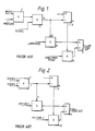
- FIGs. 1-3 Three prior systems for this type of processing are shown in Figs. 1-3. Although the processing is carried out is a similar manner by all three the inputs and outputs of each system are different.
- Fig. 1 In video graphics equipment there are two requirements that can be met by this type of processor, the need to produce new images under operator control to give the effect of painting and to combine signals from two or more sources of image signals so that the output image can contain areas of image signals from one or all the sources.
- the circuit shown in Fig. 1 is a so-called the brush processor, described in UK 2089625 (which is incorporated herein by reference), used in Quantel's video graphic system to create new images.
- the image is produced by combining new video signals representing luminance or chrominance with signals stored in a framestore in proportions determined by a control signal K.
- the luminance and chrominance signals to be used are chosen by the operator as is also the notional artists implement to be used in the creation.
- Command signals can be input to the system by the operator by the use of a stylus and touch tablet to identify image points at which 'paint' is to be 'applied'.
- the control signal K for each identified image point is produced at the output of multiplier 2 in Fig. 1 and results from the multiplication of first a brush signal, which is a signal relating to the distribution power of the notional implement chosen by the operator, second a signal relating to the pressure applied by the operator to the stylus and third a stencil signal.
- the operation of a stencil in this system is analogous to that in the conventional artists equipment. Where the operator has not chosen to use a stencil this signal will be set to 1 and so K will be simply brush signal times pressure. K will always be a value between 0 and 1.
- the processing is done picture point by picture point but K may be precalculated for each picture point as described in co-pending EP application no 86302545.8, however this will not effect the operation of this circuit.
- the output is produced by multiplying the incoming luminance chosen by the operator by K in multiplier 3 and adding this to the luminance times 1-K in 5.
- the luminance applied to 5 is the luminance generated for the particular picture point from previous operations of the system. It will be obvious that the output is then K L in + (1-K) L store, where L in is the incoming luminance and L store is the luminance stored at that point. It is found that this processing gives a very realistic image.
- Fig. 2 shows a processor which can combine two picture sources in a way which produces an output image which contains different areas of each image as described in UK Patent No. 2113950 (which is incorporated herein by reference). Where one image is moved relative to the second, parts of the that image may be made to appear as they move in front of objects in the stationary image.
- Each picture source is provided with a stencil signal which consists of signals for each picture point having a value between 0 and 1 and these signals are multiplied together to provide a control signal k at the output of multiplier 7.
- the control signal k is again a digital signal with a value between 0 and 1 and is used to determine the proportions in which the two picture signals are combined.
- the output from adder 11 in Fig. 2 is kP1 + (1-k)P2 where P1 is a signal from the first picture source and P2 is a signal from the second picture source.
- the circuit components needed to achieve this are the same components as in 2 to 6 Fig. 1 arrangement but the circuits are not usually combined.
- By calculating the stencil signals for each picture source it can be provided that where those areas in picture 1 are to appear on the output image k will be large and vice versa, where picture 2 is to appear. Additional circuitry is of course provided to produce the addressing and to move one picture relative to the second.
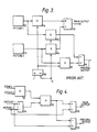
- the prior art system shown in Fig. 3 is a processor used in still store systems which may be part of a video graphics system.
- one facility that is desirable is to be able to view the contents of one store and at the same time preview the contents of a second store and to be able to cut or fade from one to the other.
- the control value K in the processing in this case can be used then to achieve fade by gradually changing from 1 to 0 or cut by changing more abruptly.
- Two still pictures are stored in framestores 12 and 13 and then output to the multipliers 14-17.
- the factor K is applied as a second input to multipliers 15 and 16 and 1-K to multiplier 14 and 17 and it will be obvious from Fig.
- the aim of the present invention is to provide a means for carrying out these three types of processing which is less expensive in terms of components.
- a video processing circuit comprising:
- a video processing system comprising, input means for video signals from a plurality of sources, input means for a plurality of signals, selector means for selecting video signals from more than one source and for selecting one or more control signals, combining means for combining said selected control signals to produce a combined control signal, processing means for combining the selected video signals in proportions determined by said combined control signal, said processing means being capable of operating in more than one mode, producing one video output which is the combination of two or more input signals, and the second mode producing two video outputs with one output being the input signals combined in the reverse proportions to the combination of the signals in the other output, and means for selecting the mode of operation of the processing means.
- the input selector 30 selects any of a number of control signals and video signal inputs the selection being dependent on the mode in which the circuit is to operate.
- the operator When the circuit is to operate as a brush processor for video graphics systems the operator provides signals via the control 31 which cause input selector 30 to select luminance from the framestore (not shown) as the luminance 2 (L2) (50) input and new luminance (49) as luminance 1 (L1) input and also selects brush signals which represent graphic parameters of chosen implements, a pressure signal and a stencil signal as the control signals.
- the operator of the video graphics system causes the image to be generated by 'drawing on a touch tablet with a pressure sensitive stylus'.
- values of brush (46) and pressure signals (45) for a pixel of the image are input to multiplier 32 before that pixel is present on the input to the processor and the output of multiplier 32 is delayed in delay 33 until the corresponding pixel arrives.
- the product of brush (46) and pressure (45) is then reapplied to the multiplier 32 with the stencil 1 signal, to form a second product.
- Luminance values L1 and L2 are presented to the subtractor 34 at this time and the difference L1-L2 is applied to the multiplier 35 to be multiplied by the said second product of brush (46), pressure (45) and stencil 1.
- the output from multiplier 32 is the control signal K used in the processing and is, say, an 8 bit digital signal representing a number between 0 and 1.
- the incoming luminance signals are also 8 bit digital signals.
- Subtractor 34 provides as an output (L1-L2) and this is applied to multiplier 35 as one input while the second input is the K signal.
- the output of this multiplier is K(L1-L2) and the most significant bits of these output bits pass to adder 38 whilst the remaining pass via switch 41 to component 39 which in this case acts as an adder.
- Adder 38 receives as a second input the luminance L2 from the store L2 delayed in delay 36, and the output from the adder is KL1 + (1-K)L2 which is the new picture point and this can be stored in the framestore at the correct address and can also be viewed on a display.
- the second adder 39 is provided for the reminder because if K is very small information will be lost if only the first 8 bits are used.
- the second input to the adder will be zero and after that will be the output of adder 39.
- the value has accumulated beyond the eight bits in this output switch 42 operates to increase the output produced in adder 38 by the correct amount. This is a well known technique for these types of system.
- the operation of the circuit is much the same as described above when two images are to be combined.
- the inputs are luminance signals representing two images and the control signals are the stencil signals (47, 48) corresponding to those images.
- the images to be combined may in fact have been produced by a video graphics system in the way described above and the stencils could also have been produced in a graphics system.
- the two stencil signals are multiplied in multiplier 32 to give the control signal K which can be selected by the output selector to form the stencil signal for the resultant image as well as being applied to multiplier 35.
- the output image may be viewed on a display. The facility for using the remainder of the output of 35 is not required in this processing.
- Subtractor 39 receives an input of K(P1-P2) but subtracts this from P1 to give the preview output of KP2 +(1-K)P1. It can be seen that this circuit gives the same outputs as the circuits in Fig. 3 but using fewer multipliers which gives a saving in cost.
Landscapes
- Engineering & Computer Science (AREA)
- Theoretical Computer Science (AREA)
- General Engineering & Computer Science (AREA)
- Physics & Mathematics (AREA)
- General Physics & Mathematics (AREA)
- Human Computer Interaction (AREA)
- Studio Circuits (AREA)
Applications Claiming Priority (2)
| Application Number | Priority Date | Filing Date | Title |
|---|---|---|---|
| GB858525174A GB8525174D0 (en) | 1985-10-11 | 1985-10-11 | Video image processing systems |
| GB8525174 | 1985-10-11 |
Publications (2)
| Publication Number | Publication Date |
|---|---|
| EP0219251A2 true EP0219251A2 (de) | 1987-04-22 |
| EP0219251A3 EP0219251A3 (de) | 1989-12-06 |
Family
ID=10586564
Family Applications (1)
| Application Number | Title | Priority Date | Filing Date |
|---|---|---|---|
| EP86307369A Withdrawn EP0219251A3 (de) | 1985-10-11 | 1986-09-25 | Videobildverarbeitungssysteme |
Country Status (2)
| Country | Link |
|---|---|
| EP (1) | EP0219251A3 (de) |
| GB (1) | GB8525174D0 (de) |
Cited By (2)
| Publication number | Priority date | Publication date | Assignee | Title |
|---|---|---|---|---|
| EP0403054A3 (de) * | 1989-04-17 | 1991-04-03 | Quantel Limited | Elektronisches graphisches System |
| WO1991012586A1 (en) * | 1990-02-08 | 1991-08-22 | Crosfield Electronics Limited | Graphics system |
Family Cites Families (3)
| Publication number | Priority date | Publication date | Assignee | Title |
|---|---|---|---|---|
| GB2140257B (en) * | 1980-12-04 | 1985-09-18 | Quantel Ltd | Video image creation |
| NL8105223A (nl) * | 1981-11-18 | 1983-06-16 | Philips Nv | Inrichting voor verschilbeeldbepaling. |
| GB2113950B (en) * | 1982-01-15 | 1986-10-01 | Quantel Ltd | Image composition system |
-
1985
- 1985-10-11 GB GB858525174A patent/GB8525174D0/en active Pending
-
1986
- 1986-09-25 EP EP86307369A patent/EP0219251A3/de not_active Withdrawn
Cited By (3)
| Publication number | Priority date | Publication date | Assignee | Title |
|---|---|---|---|---|
| EP0403054A3 (de) * | 1989-04-17 | 1991-04-03 | Quantel Limited | Elektronisches graphisches System |
| US5276787A (en) * | 1989-04-17 | 1994-01-04 | Quantel Limited | Electronic graphic system |
| WO1991012586A1 (en) * | 1990-02-08 | 1991-08-22 | Crosfield Electronics Limited | Graphics system |
Also Published As
| Publication number | Publication date |
|---|---|
| EP0219251A3 (de) | 1989-12-06 |
| GB8525174D0 (en) | 1985-11-13 |
Similar Documents
| Publication | Publication Date | Title |
|---|---|---|
| EP0423930B1 (de) | Elektronisches Grafikystem mit niedriger Kontrollbildauflösung | |
| US5077610A (en) | Previewing cuts and transformations in an electronic image composition system | |
| US4602286A (en) | Video processing for composite images | |
| US5384912A (en) | Real time video image processing system | |
| EP0344976B1 (de) | Bilderzeugungsgerät | |
| US4851912A (en) | Apparatus for combining video signals | |
| US5090909A (en) | Video graphic simulator systems | |
| US5404447A (en) | Apparatus for manipulating image pixel streams to generate an output image pixel stream in response to a selected mode | |
| US20070253640A1 (en) | Image manipulation method and apparatus | |
| JPH021894A (ja) | 物体の色特性を発生する方法と装置 | |
| JPH0473189B2 (de) | ||
| GB2113950A (en) | Image composition system | |
| US4949180A (en) | Video image processing systems | |
| EP0716541B1 (de) | Vorrichtung zur Mischung von Videosignalen | |
| GB2157122A (en) | Image composition system | |
| US4775858A (en) | Video image creation | |
| EP0260998B1 (de) | Verarbeitung von Videobildsignalen | |
| EP0568361A2 (de) | Farbes Erzeug- und Mischvorrichtung | |
| KR19990078196A (ko) | 화상혼색처리장치 | |
| EP0486468B1 (de) | Verarbeitungsschaltung für Videosignale | |
| EP0219251A2 (de) | Videobildverarbeitungssysteme | |
| EP0314250A2 (de) | Digitale Verarbeitung und Anzeige von analogischen Videosignalen | |
| GB2287601A (en) | Self keyer with background gap fill | |
| GB2158671A (en) | Improvements in or relating to video signal processing systems | |
| EP0264963B1 (de) | Verfahren und Anordnung zur Erzeugung von Fernsehtrickeffekten |
Legal Events
| Date | Code | Title | Description |
|---|---|---|---|
| PUAI | Public reference made under article 153(3) epc to a published international application that has entered the european phase |
Free format text: ORIGINAL CODE: 0009012 |
|
| AK | Designated contracting states |
Kind code of ref document: A2 Designated state(s): DE FR GB |
|
| PUAL | Search report despatched |
Free format text: ORIGINAL CODE: 0009013 |
|
| AK | Designated contracting states |
Kind code of ref document: A3 Designated state(s): DE FR GB |
|
| 17P | Request for examination filed |
Effective date: 19900105 |
|
| 17Q | First examination report despatched |
Effective date: 19920514 |
|
| STAA | Information on the status of an ep patent application or granted ep patent |
Free format text: STATUS: THE APPLICATION IS DEEMED TO BE WITHDRAWN |
|
| 18D | Application deemed to be withdrawn |
Effective date: 19940108 |
|
| RIN1 | Information on inventor provided before grant (corrected) |
Inventor name: MILES, BARRY DONALD RUBERRY |