EP0219268B1 - Rohraufweiterkopf - Google Patents
Rohraufweiterkopf Download PDFInfo
- Publication number
- EP0219268B1 EP0219268B1 EP86307544A EP86307544A EP0219268B1 EP 0219268 B1 EP0219268 B1 EP 0219268B1 EP 86307544 A EP86307544 A EP 86307544A EP 86307544 A EP86307544 A EP 86307544A EP 0219268 B1 EP0219268 B1 EP 0219268B1
- Authority
- EP
- European Patent Office
- Prior art keywords
- expander
- segments
- annular
- pin
- head
- Prior art date
- Legal status (The legal status is an assumption and is not a legal conclusion. Google has not performed a legal analysis and makes no representation as to the accuracy of the status listed.)
- Expired - Lifetime
Links
- 230000008878 coupling Effects 0.000 claims description 4
- 238000010168 coupling process Methods 0.000 claims description 4
- 238000005859 coupling reaction Methods 0.000 claims description 4
- 230000014759 maintenance of location Effects 0.000 description 1
- 230000004048 modification Effects 0.000 description 1
- 238000012986 modification Methods 0.000 description 1
Images


Classifications
-
- B—PERFORMING OPERATIONS; TRANSPORTING
- B21—MECHANICAL METAL-WORKING WITHOUT ESSENTIALLY REMOVING MATERIAL; PUNCHING METAL
- B21D—WORKING OR PROCESSING OF SHEET METAL OR METAL TUBES, RODS OR PROFILES WITHOUT ESSENTIALLY REMOVING MATERIAL; PUNCHING METAL
- B21D39/00—Application of procedures in order to connect objects or parts, e.g. coating with sheet metal otherwise than by plating; Tube expanders
- B21D39/08—Tube expanders
- B21D39/20—Tube expanders with mandrels, e.g. expandable
-
- B—PERFORMING OPERATIONS; TRANSPORTING
- B21—MECHANICAL METAL-WORKING WITHOUT ESSENTIALLY REMOVING MATERIAL; PUNCHING METAL
- B21D—WORKING OR PROCESSING OF SHEET METAL OR METAL TUBES, RODS OR PROFILES WITHOUT ESSENTIALLY REMOVING MATERIAL; PUNCHING METAL
- B21D41/00—Application of procedures in order to alter the diameter of tube ends
- B21D41/02—Enlarging
- B21D41/026—Enlarging by means of mandrels
Definitions
- Pipe expanders are used to expand the end of pipes to enable pipes to be coupled together or to expand an opening in the side of a pipe to enable another pipe to be inserted into that opening to form a T-piece.
- the pipe expander is primarily intended for expanding pipes, it should be understood that the pipe expander could be used to expand other generally cylindrical articles.
- Conventional pipe expanders include a expander head which has a plurality of annular step portions which increase in diameter from the centre of the head to provide a plurality of expanding portions for expanding pipes of different diameters.
- US-A-1,830,235 discloses an expander head having the features of the precharacterising portion of claim 1.
- US-A-1,830,235 relates to ring expander and more particularly to devices for stretching finger rings.
- US-A-1,539,643 discloses in combination a flue expander including an expansible head, a tapered expanding pin of polygonal cross-section, an extractor mounted upon said pin and provided with a polygonal boreforfitting about the pin, said extractor being adapted to have pressure applied thereto to release the expansible flue expanding head, and means for preventing removal of the expansible head from the pin.
- FR-A-2,380,831 discloses an apparatus for forming interlocking portions at the ends of tubes which has one cylindrical expander portion having a tapered axial bore and comprising a plurality of segments which are forced radially outwardly by a tapered plunger which is forced into the axial bore by a rack and pinion mechanism operated by a lever arm.
- US-A-3,164,045 discloses a tube swaging tool comprising a number of concentric swages, each swage comprising a swaging surface connected via a cam surface to a swage guide section terminating in a level.
- the expander head can generally only be used for expanding small side openings in the wall of the pipe because the expander head abuts the opposite extremity of the pipe wall thereby preventing the pipe from being inserted onto the expander head to engage the larger diameter expanding portions.
- the present invention provides an expander head, said expander head having a plurality of segments, resilient coupling means for coupling the segments together, said segments being adapted to be forced radially outwardly with respect to one another in order to expand a work piece, said segments each having a plurality of stepped arcuate expanding portions which form annular expanding portions when the segments are coupled together, said annular expanding portions comprising a plurality of radial annular surfaces extending in a generally radial direction and a plurality of adjacent axial annular surfaces extending in a generally axial direction so as to form a corresponding plurality of steps therewith characterised in that the expander head is a pipe expander head and further comprises a plurality of annular recesses of preselected depth extending in a generally axial direction between axial annular surfaces of adjacent annular expanding portions, each said recess extending from a radial annular surface of one said annular expanding portion and having a radially inner wall extending along its length so as to form a continuation of
- said segments form a disk when coupled together and said means for driving the segments comprises a substantially central opening in said disk, a tapered pin for location in said opening and means for driving said pin into said opening such that as the tapered pin is inserted into said opening, said segments are forced radially outwardly to cause expansion of said work piece.
- said means for driving the segments comprises a substantially central opening in said generally annular disk, a tapered pin for location in said opening and means for driving said pin into said opening such that as the tapered pin is inserted into said opening, said segments are forced said radially outwardly to cause expansion of said work piece.
- the means for driving the pin comprises a plurality of teeth arranged on said pin for engagement with a gear assembly and a handle for rotating said gear assembly such that rotation of the gear assembly causes said pin to be driven into and out of said opening in the generally annular disk to force the segments radially outwardly to expand a work piece.
- the pin comprises a shank portion which includes said teeth and a tapered head portion which is driven into said opening.
- said opening of the expander head is a tapered opening which matches the taper of the head portion of the pin. and the opening being formed by an arcuate notch at the apex of each segment which forms the annular disk.
- each segment includes an elongate slot for engagement with a stud, said stud supporting the expander head on the pipe expander and enabling radially outward movement of each segment by virtue of relative movement of the stud in said elongate slot.
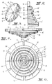
- Figure 13 shows a conventional expander head which comprises a plurality of step portions 15, 17, 19 and 21.
- the step portions 15 to 21 form expander portions for receipt of a generally cylindrical work piece and when segments 23 and 25 are moved radially outwardly in the direction of arrows A, the work piece is expanded.
- the expander head shown in Figure 13 is relatively thick in the direction of arrow T to enable a number of different diameter expanding portions 15, 17, 19 and 21 to be provided on the one expander head.
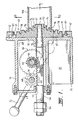
- a housing 30 which may be cast from suitable material or which may be formed by other means.
- the housing 30 includes a generally front flat plate 32 provided with an opening 34 and a base plate 35 and gusset 37 for enabling the expander to be connected to a work bench.
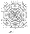
- An expander head 40 is mounted to front plate 32 by an annular mounting ring 42 which is secured to the front plate 32 by bolts 46 (see Figure 2).
- the bolts 46 are provided in elongate holes 48 which have an enlarged open end 50 so that the mounting ring 42 can be removed from the front plate 32 by loosening the bolts 46 which are threaded into the front plate 32 and rotating the mounting ring 42 in the direction of arrow B so that the enlarged openings 50 are aligned with the head of the bolts 46 so that the ring 42 can be simply slid of the bolts 46 without the need to completely remove the bolts 46 from the plate 32.
- a pin 50 is mounted to extend through a rear opening 52 in housing 30 and includes a tapered head 54 which extends through opening 34.
- the pin 50 has a pair of bolts 56 arranged at its outer end which act as a stop to limit inward movement (to be described hereinafter) of the pin 50.
- the pin 50 is provided with a plurality of teeth 60 which generally form a rack on the pin 50.
- the teeth 60 engage a gear 62 which is mounted on a shaft 64.
- a larger gear 66 is also mounted on shaft 64 and which meshes with a further gear 68 arranged on shaft 70.
- the shaft 70 is connected to a handle 72. It should be noted that if the housing 30 is cast the housing 30 is provided with bosses 31 (see Figure 4) which are drilled to support the shafts 64 and 70. If necessary suitable bushings or bearings could be provided in the bosses 31.
- the head 40 is formed of six segments 39, 41, 43, 45, 47 and 49.
- the outer periphery of each segment includes an elongate slot 51 and the inner apex of each segment is inwardly curved so that when the segments are placed together as shown in Figures 5 and 6 a central opening 61 is formed.
- the opening 61 is tapered as is best seen in Figures 1 and 3 to match the taper of head 54 of pin 50.
- each segment is provided with a plurality of annular recesses (71, 73, 75) of preselected length extending in a generally axial direction between axial annular surfaces of adjacent annular expanding portions, each said recess extending from a radial annular surface of one said annular expanding portion and having a radially inner wall extending along its length so as to form a continuation of the axial annular surface (71b, 73b, 75b) of said one annular expanding portion so that the axial thickness of said expander head is reduced by an amount proportional to the sum of the length of the walls of each recess.
- the annular step portions are of different diameter with the smaller diameter step portion being axially outward of the larger diameter step portions.
- the surfaces (71 b, 73b, 75b) and the radially inner walls of the recesses (71, 73, 75) form expander walls for engaging a work piece in order to expand the work piece.
- the expander head according to this invention includes recesses, the expander head is much thinner in the direction of arrow T shown in Figure 8 since part of the expander wall of each expanding portion 72 to 76 is formed in a recess 80. It should be noted that the outer most expanding portion 78 does not require a recess but is merely stepped just before the inner most portion of elongate slots 51.
- Each segment 39 to 49 includes a semi-circular channel 90 which forms an annular channel 92 when the segments are joined together.
- the annular channel 90 has side walls 92 and 94which are angled outwardly with respect to the axial direction of the head 40 and the channel 90 receives a spring element 96 such as spring wire or an annular expanding coil spring which joins the segments 39 to 49 together and holds the segments together for radial movement as will be described hereinafter.
- the diameter of the step portions 72 to 78 can be selected as desired to accord with the diameter of pipes or the like with which the pipe expander is to be used.
- pipes of four different diameters can be accommodated whilst providing a relatively thin expander head.
- pipes or other work pieces in which a minimal of space is provided can be used even on the larger diameter expander portions since less room is required in the work piece to receive the smaller expander portions 72, 74 or 76.
- a work piece 100 such as a pipe or the like which is to be joined to another pipe is required to have one end of the pipe expanded so that the other pipe of the same diameter can be slipped into the expanded end and joined to the pipe 100.
- the pipe 100 is fitted over the expander portion which has a diameter corresponding to the internal diameter of the pipe 100. In the embodiment shown in Figures 1 and 3, that portion is the portion 76.
- handle 72 which is coupled to a sleeve 102 joined to shaft 70 is rotated in the appropriate direction to rotate shaft 70 and thereby gear 68 which rotates gear 66 in view of the meshing of the gear 68 and 66.
- Rotation of gear 66 rotates shaft 64 and gear 62 which is in engagement with the teeth 60 on pin 50.
- Rotation of gear 62 drives the pin 50 in the direction of arrow C in Figures 1 and 3 to force the tapered head 54 of the pin 50 into the tapered opening 61 of the head 40.
- the tapered head 54 moves into the opening 61 it forces the segments 39 to 49 of the head 40 radially outward, in the direction of arrow D in Figures 1 and 3, against the bias of the spring element 96 which holds the segments 39 to 49 together.
- the segments 39 to 49 are driven radially outwardly the end of pipe 100 is forced radially outwardly to expand the end of the pipe 100 as is shown in Figure 3.
- the handle 72 which is rotated in the opposite direction to withdraw the pin 50.
- the pipe 100 is removed so that the segments 39 to 49 can be drawn radially inwardly by the spring element 96 to their original position.
- the preferred embodiment of the invention therefore provides an expander head which can be used with work pieces even where space is minimal and can perform an expanding operation very quickly.
Landscapes
- Engineering & Computer Science (AREA)
- Mechanical Engineering (AREA)
- Rigid Pipes And Flexible Pipes (AREA)
- Mutual Connection Of Rods And Tubes (AREA)
- Earth Drilling (AREA)
- Quick-Acting Or Multi-Walled Pipe Joints (AREA)
- Analysing Materials By The Use Of Radiation (AREA)
- Pipe Accessories (AREA)
- Paper (AREA)
- Particle Accelerators (AREA)
Claims (8)
Priority Applications (1)
| Application Number | Priority Date | Filing Date | Title |
|---|---|---|---|
| AT86307544T ATE49358T1 (de) | 1985-10-10 | 1986-10-01 | Rohraufweiterkopf. |
Applications Claiming Priority (2)
| Application Number | Priority Date | Filing Date | Title |
|---|---|---|---|
| AUPH284285 | 1985-10-10 | ||
| AU2842/85 | 1985-10-10 |
Publications (3)
| Publication Number | Publication Date |
|---|---|
| EP0219268A2 EP0219268A2 (de) | 1987-04-22 |
| EP0219268A3 EP0219268A3 (en) | 1987-10-07 |
| EP0219268B1 true EP0219268B1 (de) | 1990-01-10 |
Family
ID=3771314
Family Applications (1)
| Application Number | Title | Priority Date | Filing Date |
|---|---|---|---|
| EP86307544A Expired - Lifetime EP0219268B1 (de) | 1985-10-10 | 1986-10-01 | Rohraufweiterkopf |
Country Status (7)
| Country | Link |
|---|---|
| US (1) | US4733551A (de) |
| EP (1) | EP0219268B1 (de) |
| JP (1) | JPS6289534A (de) |
| AT (1) | ATE49358T1 (de) |
| CA (1) | CA1267599A (de) |
| DE (1) | DE3668123D1 (de) |
| NZ (1) | NZ217685A (de) |
Families Citing this family (19)
| Publication number | Priority date | Publication date | Assignee | Title |
|---|---|---|---|---|
| WO1990012665A1 (en) * | 1989-04-21 | 1990-11-01 | W.E.B. Tooling Pty. Ltd. | Pipe expander |
| US4987763A (en) * | 1989-08-24 | 1991-01-29 | O. M. S., Inc. | Tool in kit form for deforming metal |
| US5033301A (en) * | 1990-02-28 | 1991-07-23 | O.M.S., Inc. | Coupling for a gas pipe joint and associated method for making same and device therefor |
| US5138863A (en) * | 1990-03-05 | 1992-08-18 | O.M.S., Inc. | Coupling for a gas pipe joint and associated method for making same and device therefor |
| DE4200020C1 (en) * | 1992-01-02 | 1993-07-22 | Rothenberger Werkzeuge-Maschinen Gmbh, 6233 Kelkheim, De | Hollow, cylindrical workpiece widening tool - has rack teeth on sliding mandrel meshing with teeth on hinged, L=shaped handle |
| FR2738512B1 (fr) * | 1995-09-07 | 1997-10-10 | Sepma Sa | Dispositif d'ecartement pour assurer l'expansion radiale d'un manchon deformable |
| DE19834003A1 (de) * | 1998-07-29 | 2000-02-03 | Adam Gerich | Montagehilfe für eine Befestigungsvorrichtung, insbesondere für Schlauch- oder Rohranschlüsse |
| US6862766B2 (en) | 2002-04-16 | 2005-03-08 | Malco Products, Inc. | Hand tool for expanding pipe ends and pressing sleeves onto fittings |
| US7059162B1 (en) * | 2004-08-05 | 2006-06-13 | Capewell Components, Llc | Dual flaring tool |
| WO2007132799A1 (ja) * | 2006-05-15 | 2007-11-22 | Komatsu Ltd. | 鋼管の拡管成形方法および鋼管の拡管成形装置 |
| DE102008061442A1 (de) * | 2008-10-27 | 2010-09-02 | Transitron Handels-Gmbh | Multidimensions-Rohraufweitvorrichtung |
| US8517715B2 (en) | 2010-04-06 | 2013-08-27 | Milwaukee Electric Tool Corporation | PEX expanding tool |
| US9914260B2 (en) | 2014-06-20 | 2018-03-13 | Milwaukee Electric Tool Corporation | PEX expanding tool |
| US9862137B2 (en) | 2015-04-20 | 2018-01-09 | Milwaukee Electric Tool Corporation | PEX expanding tool |
| WO2016201196A1 (en) | 2015-06-10 | 2016-12-15 | Milwaukee Electric Tool Corporation | Pex expanding tool |
| US11633775B2 (en) * | 2019-02-20 | 2023-04-25 | Milwaukee Electric Tool Corporation | PEX expansion tool |
| EP4610038A1 (de) | 2019-02-20 | 2025-09-03 | Milwaukee Electric Tool Corporation | Werkzeug zur pex-aufweitung |
| CN214726466U (zh) | 2020-11-27 | 2021-11-16 | 米沃奇电动工具公司 | 扩展工具 |
| US11779990B2 (en) | 2021-04-09 | 2023-10-10 | Milwaukee Electric Tool Corporation | Expansion tool |
Family Cites Families (10)
| Publication number | Priority date | Publication date | Assignee | Title |
|---|---|---|---|---|
| US157875A (en) * | 1874-12-15 | Improvement in boiler-tube expanders | ||
| US417323A (en) * | 1889-12-17 | Tube-expander | ||
| US691446A (en) * | 1900-11-03 | 1902-01-21 | Automatic Racking Machine Company | Hose-thimble expander. |
| US1057664A (en) * | 1911-11-08 | 1913-04-01 | Patterson Allen Engineering Company | Die for pipe-flanging machines. |
| US1539643A (en) * | 1923-09-22 | 1925-05-26 | Bush Carl | Flue expander |
| US1830235A (en) * | 1929-06-13 | 1931-11-03 | Mazer Joseph | Ring expander |
| US3164045A (en) * | 1961-06-08 | 1965-01-05 | Kennedy Michael Lee | Tube swaging tool |
| US3812704A (en) * | 1970-01-02 | 1974-05-28 | Imp Eastman Corp | Apparatus for making up an expandable insert fitting |
| DE2616324A1 (de) * | 1976-04-14 | 1977-10-27 | Kabel Metallwerke Ghh | Vorrichtung zum kalibrieren von rohrenden |
| FR2380831A1 (fr) * | 1977-02-22 | 1978-09-15 | Beauvillier & Cie | Appareil a former des emboitures |
-
1986
- 1986-09-25 NZ NZ217685A patent/NZ217685A/xx unknown
- 1986-09-25 CA CA000519057A patent/CA1267599A/en not_active Expired - Lifetime
- 1986-09-25 US US06/912,049 patent/US4733551A/en not_active Expired - Fee Related
- 1986-10-01 AT AT86307544T patent/ATE49358T1/de not_active IP Right Cessation
- 1986-10-01 EP EP86307544A patent/EP0219268B1/de not_active Expired - Lifetime
- 1986-10-01 DE DE8686307544T patent/DE3668123D1/de not_active Expired - Lifetime
- 1986-10-09 JP JP61239390A patent/JPS6289534A/ja active Pending
Also Published As
| Publication number | Publication date |
|---|---|
| CA1267599A (en) | 1990-04-10 |
| ATE49358T1 (de) | 1990-01-15 |
| EP0219268A3 (en) | 1987-10-07 |
| DE3668123D1 (de) | 1990-02-15 |
| US4733551A (en) | 1988-03-29 |
| JPS6289534A (ja) | 1987-04-24 |
| NZ217685A (en) | 1988-11-29 |
| EP0219268A2 (de) | 1987-04-22 |
Similar Documents
| Publication | Publication Date | Title |
|---|---|---|
| EP0219268B1 (de) | Rohraufweiterkopf | |
| US6386789B1 (en) | Quick release ball type locking pin and production tool | |
| KR950012448B1 (ko) | 분리가능하게 장착하는 공구 홀더 및 그 장착방법 | |
| JPH03501368A (ja) | 工具ホルダを保持する錠止ロットならびに装置 | |
| KR101723671B1 (ko) | 확관기용 헤드 | |
| JP2000158270A (ja) | ツールホルダ | |
| EP0291439B1 (de) | Gewindeschneideeinheit | |
| CA2101724A1 (en) | Modular Expandable Honing Tool | |
| JP2002254130A (ja) | スピンドルまわりに回転可能な環状溝つきくせ取りローラのための着脱機構 | |
| JPS5920944Y2 (ja) | 管を管板から取外すための装置 | |
| US4785649A (en) | Tapered thread roll-forming machine | |
| US5882139A (en) | Method of sleeving an at least locally cylindrical part into a tubular part in a cruciform arrangement, tool for implementing said method, and assembly of two parts sleeved together by said method | |
| US4043171A (en) | Branch tool | |
| JPS5835804B2 (ja) | 内歯歯車を有する工作物のコレツトチヤツク | |
| US4541163A (en) | Hub starter fixture | |
| US7526940B2 (en) | Die element changing devices | |
| EP0304388B1 (de) | Nippelfutter | |
| AU596117B2 (en) | Pipe expander | |
| US4106784A (en) | Finisher's mandrel | |
| US3269006A (en) | Method of swaging metal tubes onto internal members | |
| JPH10274261A (ja) | 電磁式クラッチアセンブリ用の回転子の製造方法 | |
| US4467631A (en) | Apparatus for splining thin-wall power transmission sleeves | |
| JPH08257813A (ja) | チャック | |
| US1802655A (en) | Lathe chuck | |
| EP1215018A1 (de) | Vorrichtung zum Verbinden eines Werkzeuges mit einem Roboterarm mittels Verriegelungskugeln |
Legal Events
| Date | Code | Title | Description |
|---|---|---|---|
| PUAI | Public reference made under article 153(3) epc to a published international application that has entered the european phase |
Free format text: ORIGINAL CODE: 0009012 |
|
| AK | Designated contracting states |
Kind code of ref document: A2 Designated state(s): AT BE CH DE FR GB IT LI LU NL SE |
|
| PUAL | Search report despatched |
Free format text: ORIGINAL CODE: 0009013 |
|
| AK | Designated contracting states |
Kind code of ref document: A3 Designated state(s): AT BE CH DE FR GB IT LI LU NL SE |
|
| 17P | Request for examination filed |
Effective date: 19880331 |
|
| 17Q | First examination report despatched |
Effective date: 19880624 |
|
| GRAA | (expected) grant |
Free format text: ORIGINAL CODE: 0009210 |
|
| AK | Designated contracting states |
Kind code of ref document: B1 Designated state(s): AT BE CH DE FR GB IT LI LU NL SE |
|
| REF | Corresponds to: |
Ref document number: 49358 Country of ref document: AT Date of ref document: 19900115 Kind code of ref document: T |
|
| ITF | It: translation for a ep patent filed | ||
| REF | Corresponds to: |
Ref document number: 3668123 Country of ref document: DE Date of ref document: 19900215 |
|
| ET | Fr: translation filed | ||
| PG25 | Lapsed in a contracting state [announced via postgrant information from national office to epo] |
Ref country code: GB Effective date: 19901001 Ref country code: AT Effective date: 19901001 |
|
| PG25 | Lapsed in a contracting state [announced via postgrant information from national office to epo] |
Ref country code: SE Effective date: 19901002 |
|
| PG25 | Lapsed in a contracting state [announced via postgrant information from national office to epo] |
Ref country code: LU Free format text: LAPSE BECAUSE OF NON-PAYMENT OF DUE FEES Effective date: 19901031 Ref country code: LI Effective date: 19901031 Ref country code: CH Effective date: 19901031 Ref country code: BE Effective date: 19901031 |
|
| PLBE | No opposition filed within time limit |
Free format text: ORIGINAL CODE: 0009261 |
|
| STAA | Information on the status of an ep patent application or granted ep patent |
Free format text: STATUS: NO OPPOSITION FILED WITHIN TIME LIMIT |
|
| 26N | No opposition filed | ||
| BERE | Be: lapsed |
Owner name: W.E.B. TOOLING PTY. LTD Effective date: 19901031 |
|
| PG25 | Lapsed in a contracting state [announced via postgrant information from national office to epo] |
Ref country code: NL Effective date: 19910501 |
|
| GBPC | Gb: european patent ceased through non-payment of renewal fee | ||
| NLV4 | Nl: lapsed or anulled due to non-payment of the annual fee | ||
| PG25 | Lapsed in a contracting state [announced via postgrant information from national office to epo] |
Ref country code: FR Effective date: 19910628 |
|
| REG | Reference to a national code |
Ref country code: CH Ref legal event code: PL |
|
| PG25 | Lapsed in a contracting state [announced via postgrant information from national office to epo] |
Ref country code: DE Effective date: 19910702 |
|
| REG | Reference to a national code |
Ref country code: FR Ref legal event code: ST |
|
| EUG | Se: european patent has lapsed |
Ref document number: 86307544.6 Effective date: 19910603 |
|
| PG25 | Lapsed in a contracting state [announced via postgrant information from national office to epo] |
Ref country code: IT Free format text: LAPSE BECAUSE OF NON-PAYMENT OF DUE FEES;WARNING: LAPSES OF ITALIAN PATENTS WITH EFFECTIVE DATE BEFORE 2007 MAY HAVE OCCURRED AT ANY TIME BEFORE 2007. THE CORRECT EFFECTIVE DATE MAY BE DIFFERENT FROM THE ONE RECORDED. Effective date: 20051001 |