EP0219379A1 - Verfahren und Vorrichtung zum Thermoformen von Kunststoffteilen - Google Patents
Verfahren und Vorrichtung zum Thermoformen von Kunststoffteilen Download PDFInfo
- Publication number
- EP0219379A1 EP0219379A1 EP86401947A EP86401947A EP0219379A1 EP 0219379 A1 EP0219379 A1 EP 0219379A1 EP 86401947 A EP86401947 A EP 86401947A EP 86401947 A EP86401947 A EP 86401947A EP 0219379 A1 EP0219379 A1 EP 0219379A1
- Authority
- EP
- European Patent Office
- Prior art keywords
- strip
- thermoforming
- mold
- chain
- thermoformed
- Prior art date
- Legal status (The legal status is an assumption and is not a legal conclusion. Google has not performed a legal analysis and makes no representation as to the accuracy of the status listed.)
- Granted
Links
Images


Classifications
-
- B—PERFORMING OPERATIONS; TRANSPORTING
- B29—WORKING OF PLASTICS; WORKING OF SUBSTANCES IN A PLASTIC STATE IN GENERAL
- B29C—SHAPING OR JOINING OF PLASTICS; SHAPING OF MATERIAL IN A PLASTIC STATE, NOT OTHERWISE PROVIDED FOR; AFTER-TREATMENT OF THE SHAPED PRODUCTS, e.g. REPAIRING
- B29C69/00—Combinations of shaping techniques not provided for in a single one of main groups B29C39/00 - B29C67/00, e.g. associations of moulding and joining techniques; Apparatus therefore
-
- B—PERFORMING OPERATIONS; TRANSPORTING
- B29—WORKING OF PLASTICS; WORKING OF SUBSTANCES IN A PLASTIC STATE IN GENERAL
- B29C—SHAPING OR JOINING OF PLASTICS; SHAPING OF MATERIAL IN A PLASTIC STATE, NOT OTHERWISE PROVIDED FOR; AFTER-TREATMENT OF THE SHAPED PRODUCTS, e.g. REPAIRING
- B29C51/00—Shaping by thermoforming, i.e. shaping sheets or sheet like preforms after heating, e.g. shaping sheets in matched moulds or by deep-drawing; Apparatus therefor
- B29C51/02—Combined thermoforming and manufacture of the preform
-
- B—PERFORMING OPERATIONS; TRANSPORTING
- B29—WORKING OF PLASTICS; WORKING OF SUBSTANCES IN A PLASTIC STATE IN GENERAL
- B29C—SHAPING OR JOINING OF PLASTICS; SHAPING OF MATERIAL IN A PLASTIC STATE, NOT OTHERWISE PROVIDED FOR; AFTER-TREATMENT OF THE SHAPED PRODUCTS, e.g. REPAIRING
- B29C51/00—Shaping by thermoforming, i.e. shaping sheets or sheet like preforms after heating, e.g. shaping sheets in matched moulds or by deep-drawing; Apparatus therefor
- B29C51/18—Thermoforming apparatus
- B29C51/20—Thermoforming apparatus having movable moulds or mould parts
Definitions
- thermoforming operation In order to reconcile the continuous advance of the strip and the stopping of the sheet in line with the mold during the thermoforming operation, provision is made for the creation of a loop of the sheet which gives slack.
- the strip is stopped downstream of the loop while the material continues to arrive upstream, which results in an elongation of the loop.
- the strip resumes its advance downstream of the loop and shortens it and so on, step by step.
- thermoforming In practice, there are other occasions to manufacture objects by thermoforming although they must have a much greater thickness: cases, automobile dashboards, sanitary appliances, etc.
- thermoforming it is not possible to carry out continuous thermoforming and it is necessary to go through an intermediate stage which consists in manufacturing plates from granules of synthetic material, these plates then being brought individually to a thermoforming mold. .
- thermoforming immediately after the extrusion of a strip, without constituting an intermediate product: coils or plates.
- This machine provides neither combined extrusion, nor calendering, nor obviously a cold zone between the extrusion head and a mobile reheating station with the mold, nor finally molding in linear movement with the sheet itself in permanent uniform movement.
- the heating station must act very close to the sheet and that consequently, the molding from bottom to top can only be done over a very short distance, to create small objects, of modest relief .
- the present invention makes it possible to remedy these drawbacks and to obtain a continuous thermoforming process, without creation of intermediate products (plates or coils), since the granules are passed directly to a thermoformable strip.
- the subject of the invention is a process for obtaining thermoformed parts, characterized in that a synthetic material is hot extruded into a horizontal strip (6), that this strip (6) is calendered , that it is towed horizontally in a continuous continuous movement through its marginal zones from the upstream of a thermoforming station, that the said strip (6) is heated up from that of said thermoforming station to a compatible temperature with its capacity to be thermoformed and this over only a fraction of its length substantially equal to that which is necessary for thermoforming so that there remains another fraction less hot between the place of calendering (7) and the heated fraction, than the '' the heated fraction is placed next to a mold (53), which this mold (53) is moved at the same speed and in the same direction as the strip (6), which is simultaneously carried out by thermoforming of the strip (6) and its cutting into a part constituting the soft part lée (6b) and a remaining part or "veil” comprising the marginal zones, which are removed The part (6b) molded and cut while continuing to
- the veil remaining after the thermoforming operation is fractionated and then ground and the resulting aggregate is led for recycling to an extruder (1) from which begins the cycle for obtaining the strip (6 ), this aggregate being preferably mixed with another non-recycled aggregate, as is known per se.
- the invention also relates to a device for the implementation of the above method characterized in that it comprises a extruder (1), an extrusion head (5), a grille (7) and horizontal beams (10-11) on which are provided on the one hand means (21-22) for continuously moving horizontal drive members upstream of a thermoforming station (30) for the longitudinal edges of a strip (6) of thermoformable material from the extrusion head (5) and the calender (7) and, on the other hand, guide means (40-41-42) and horizontal movement (25 to 29 - 31 to 34) back and forth of a moving assembly (30) which comprises on the one hand a thermoforming mold (53) and a counterpart located respectively below and above the location of the thermoformable strip (6) and secondly heating means (60-62) of the thermoformable strip (6) located on the side of said movable assembly (30) closest to the calender (7).
- a device for the implementation of the above method characterized in that it comprises a extruder (1), an extrusion head (5), a grille (7)
- Means being provided on the one hand for cutting the strip (6) into a thermoformed part and a remaining part or “veil” which must remain in engagement with the drive members and on the other hand to first evacuate the thermoformed part (6b) then Le vnile separated from the drive members.
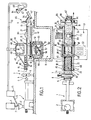
- an installation according to the invention comprises a extruder 1, the hopper 2 of which receives, by a distribution chute 3, granules placed in a distribution tank 4.
- the extruder 1 is of any known type and it is therefore not necessary to describe it in detail. It is associated with an extrusion head 5 whose orifice has the width and the height corresponding to the width and the thickness of the strip to be extruded 6.
- calender 7 also of any known type, intended to give the strip 6 a precise thickness and good mechanical strength.
- Three-cylinder calenders of known type are intended to create a strip in which plates are cut before storage and shipment so that downstream of the calender The extruded strip must be at a relatively low temperature. It will be explained later in detail why the process according to the invention provides for substantially different temperatures since it is not necessary to cool as much.
- the extruded strip must be at a temperature, at the outlet of the calender, clearly higher than that of known installations, which gives it the ability to be then reheated to the thermoforming temperature more easily, without losing its mechanical strength thanks to à The presence of a "cold" zone between the radiator outlet and the reheating station.
- the longitudinal members 10 and 11 In the vicinity of their opposite ends, the longitudinal members 10 and 11 have pinions 15, 16, 17, 18.
- the pinions 16 and 18 are coupled by an axle 19 and the pinion 16 is connected to a control motor 20.
- an all-or-nothing clutch can be provided between the pinion 24 and the pinion 18 so that the pinion 24 can be quickly uncoupled and immobilized although the pinion 18 continues to be driven by the axle 19 and the motor 20.
- a chain 25 which meshes with a pinion 26 by means of two return pinions 27 and 28, these last three pinions being mounted on a plate 29 secured to a crew mobile 30 which also carries a support 31 for a motor 32 driving in a control pinion 33 with which the pinion 26 is coupled by means of a chain or belt 34.
- the plate 29 being integral with the movable assembly 30, the latter is therefore driven in the same direction and at the same speed as the chains with pins 21 and 22.
- the crew 30 can be immobilized or driven in one direction or the other according to the speed of the engine. 32 and Chain 25.
- the speed of the motor 32 is established in such a way that it is greater than that of the chain 25 so that the plate assembly 29 - mobile assembly 30 - support 31 is moved in the opposite direction to that in which the strip 6 is driven by Chai - nes with barbs 21 and 22.
- the moving element 30 can be guided in its reciprocating horizontal movement either by roller assemblies 40 cooperating with horizontal guides 41, or by rollers 42 rolling on the side members 10 and 11 themselves.
- the moving element 30 comprises lateral uprights 45 and 46 which extend outside the side members 1C and 11 so that the extruded strip 6 can pass through the moving element 30.
- This latter comprises two assemblies situated respectively above and below the plane in which the band 6 extends.
- the upper part comprises flank clamps 47 of known type per se and mounted movable relative to the movable assembly 30 by means of jacks 48.
- the lower part of the mobile assembly 30 comprises a box 50 in which there is a lifting table 51 carrying a base 52 for a mold 53 of the desired shape for thermoforming the strip 6.
- the box 50 can be raised and lowered by means of jacks 55 and this independently of the lifting table 51, itself movable vertically by means of crosspieces 56 coupled to one or more jacks 57.
- the box 50 can be raised towards the horizontal plane in which the strip 6 extends according to the shapes of the mold which can be, as is known per se, in positive, in negative or mixed it is that is to say present convexities above the plane of the strip 6 only or concavities below this same plane or both convexities and concavities on either side of this plane.
- the strip 6 can move freely.
- a heating assembly which comprises a frame 60 held by tie rods 61 and serving as a support for the heating elements 62 detachably secured to the frame 60 in order to be able to adjust their position.
- the heating elements 62 interest an extent of the strip 6 located upstream of the thermoforming station and corresponding to what is necessary for thermoforming.
- the heating elements 62 can be arranged differently so that they more or less heat certain zones in order to facilitate the deformation of the strip 6 during the thermoforming.
- the heating elements 62 are individually adjustable so that they radiate more or less heat. It is thus possible, for example, to heat the strip 6 more intensely in its part close to the crew 30 than in its remote part, the latter being warmer than the first because it is closer to the grille 7 and therefore has had less time to cool down.
- a machine 65 intended to cut and split the strip 6 which remains after thermoforming and removal of the molded parts.
- the machine 65 can be of the shear or shredder type and creates relatively large fragments which are evacuated by an inclined plane 66 and fall on an elevator conveyor 67 terminating above a chute 68 of a crusher 69.
- the crusher 69 delivers into one or more tanks, which have not been shown here in order to simplify the description, and there has been shown exclusively a conduit 70 leading to a buffer tank 71 provided with a chute 72 opening above the loading hopper 2 of the extruder 1.
- the extruded band 6 is maintained at a higher temperature than what is currently practiced and which must be optimum between the mechanical strength requirements which impose a relatively low temperature and the concern to save the energy expenditure of the heating elements 62 necessary for the rise in temperature of the strip 6 at the time of its thermoforming.
- the mobile assembly 30 In the position of FIG. 1, the mobile assembly 30 is in the extreme upstream position, that is to say as close as possible to the calender 7 and the strip 6 which has been heated by the elements 62 is towed by the pins of the chains 21 and 22 so that its hottest part is located directly above the mold 53.
- the latter is in the low position, that is to say that the lifting table 51 is lowered as well as the box 50 .
- the side clamps 47 are in position high, the jacks 48 being in the retraction position.
- the motor 32 is blocked, so that the moving element 30 is driven at exactly the same speed as the strip 6 since the origin of the movement is the motor 20 which causes on the one hand the studded chains 21 and 22 and on the other hand the chain 25 of which the movable assembly 30 is made integral by the motor 32 as explained above.
- a control assembly of any known type causes the lowering of the side clamps 47 and the raising of the box 50 until the strip 6 is tightened and trapped all around of the thermoforming area, as shown in Figure 3.
- This pre-deformation of the strip 6 gives it good aptitude for more precise and more marked deformation and avoids the stresses due, in particular, to the more or less sharp edges which the mold 53 must have.
- the control unit then automatically causes the lifting table 51 to rise, and therefore the mold 53 to rise, as shown in FIG. 4.
- thermoforming operation proper is then carried out and a vacuum is applied according to arrow F2 so that the strip 6 applies faithfully against the shape of the mold 53.
- a vacuum is applied according to arrow F2 so that the strip 6 applies faithfully against the shape of the mold 53.
- thermoforming of the strip 6 was caused, the latter was cut around the part to be thermoformed so that a web remained in the strip 6 which remained in contact with the pins of the chains 21 and 22 and which therefore continues its movement from upstream to downstream, that is to say towards the cutting machine 65.
- FIGS. 1 and 2 this operation is shown diagrammatically by an arrow F3 indicating a transverse thrust to the movement of the strip 6 towards an evacuation conveyor 75.
- the sail continues its movement towards the machine 65 which cuts it transversely and longitudinally into roughly calibrated fragments 6c which fall on the conveyor 67, these fragments falling into the hopper 68 of the shredder 69 where they are reduced into granules of dimensions desired for their correct melting after transport via line 70 to tank 71.
- the heating elements 62 are allowed to raise the temperature of the strip 6 to around 150 -190 degrees Celsius for the relatively short time which corresponds to the outward cycle. of the moving element 30, that is to say during the thermoforming operation.
- the zone of the strip 6 between the calender and the reheating station is the least hot: approximately 100 ° Celsius and, thanks to this, the strip 6 has good mechanical strength, guaranteeing its tensile strength which the pins of the chains during the outward stroke, the heating elements 62 heat the part of the strip 6 which goes immediately after being thermoformed downstream.
- the box 50 advantageously opens on one of its sides so that one can have access to the interior and in particular to the mold support 52.
- the process according to the invention allows the thermoforming of parts immediately after the constitution of a strip from granules without any thermal shock, without manufacturing of intermediate products, without storage and without transport, which leads to a lowering of cost prices and an increase in quality.
- the invention applies particularly well to the thermoforming of parts in a thick strip: from several millimeters to more than one centimeter and wide: two meters and more. Control of the large mass of material represented by a strip having the above dimensions is obtained by implementing the invention, while the previously known means were only applicable to thin films for obtaining 'fine and small objects.
Landscapes
- Engineering & Computer Science (AREA)
- Mechanical Engineering (AREA)
- Manufacturing & Machinery (AREA)
- Blow-Moulding Or Thermoforming Of Plastics Or The Like (AREA)
- Casting Or Compression Moulding Of Plastics Or The Like (AREA)
- Moulds For Moulding Plastics Or The Like (AREA)
Priority Applications (1)
| Application Number | Priority Date | Filing Date | Title |
|---|---|---|---|
| AT86401947T ATE51359T1 (de) | 1985-09-11 | 1986-09-05 | Verfahren und vorrichtung zum thermoformen von kunststoffteilen. |
Applications Claiming Priority (2)
| Application Number | Priority Date | Filing Date | Title |
|---|---|---|---|
| FR8513483A FR2588501B1 (fr) | 1985-09-11 | 1985-09-11 | Procede et dispositif pour le thermoformage de pieces en matiere synthetique a partir de bandes extrudees |
| FR8513483 | 1985-09-11 |
Publications (2)
| Publication Number | Publication Date |
|---|---|
| EP0219379A1 true EP0219379A1 (de) | 1987-04-22 |
| EP0219379B1 EP0219379B1 (de) | 1990-03-28 |
Family
ID=9322812
Family Applications (1)
| Application Number | Title | Priority Date | Filing Date |
|---|---|---|---|
| EP86401947A Expired - Lifetime EP0219379B1 (de) | 1985-09-11 | 1986-09-05 | Verfahren und Vorrichtung zum Thermoformen von Kunststoffteilen |
Country Status (10)
| Country | Link |
|---|---|
| US (1) | US4883419A (de) |
| EP (1) | EP0219379B1 (de) |
| JP (1) | JPS6260628A (de) |
| KR (1) | KR870002935A (de) |
| AT (1) | ATE51359T1 (de) |
| CA (1) | CA1296851C (de) |
| DE (1) | DE3669841D1 (de) |
| ES (1) | ES2002336A6 (de) |
| FR (1) | FR2588501B1 (de) |
| RU (1) | RU1814616C (de) |
Cited By (3)
| Publication number | Priority date | Publication date | Assignee | Title |
|---|---|---|---|---|
| EP0687556A1 (de) * | 1994-06-17 | 1995-12-20 | Honda Giken Kogyo Kabushiki Kaisha | Verfahren zur Herstellung von Verbundfolie und Verbundfolie |
| EP2105279A1 (de) * | 2008-03-28 | 2009-09-30 | CP Packaging, Inc. | Hebemechanismus für Werkzeug, das auf eine Bahn in einer Verpackungsmaschine wirkt |
| US10961093B2 (en) | 2017-08-14 | 2021-03-30 | Cp Packaging, Inc. | Simplified lift mechanism for a packaging machine |
Families Citing this family (18)
| Publication number | Priority date | Publication date | Assignee | Title |
|---|---|---|---|---|
| DE4005972A1 (de) * | 1990-02-26 | 1991-08-29 | Tetra Pak Gmbh | Vorrichtung zum tiefziehen einer offenen schale |
| IT1257010B (it) * | 1992-02-03 | 1996-01-05 | Omv Spa | Procedimento ed apparecchiatura per la termoformatura e l'impilamento di oggetti cavi con fondello a partire da materiale termoplastico in nastro. |
| US5759591A (en) * | 1996-06-28 | 1998-06-02 | Maytag Corporation | Apparatus for thermoforming a plastic appliance door |
| US6497567B1 (en) | 1999-10-04 | 2002-12-24 | Serigraph Inc. | Multi-purpose processing apparatus |
| US20050258559A1 (en) * | 2000-09-01 | 2005-11-24 | Johansen Loren R | Thermoforming method and apparatus for use in an injection molding machine |
| DE10341287B4 (de) * | 2003-09-04 | 2005-12-01 | Uhlmann Pac-Systeme Gmbh & Co Kg | Verfahren und Vorrichtung zum Formen einer Formfolie |
| DE10345534A1 (de) * | 2003-09-30 | 2005-04-28 | Kiefel Ag | Thermoformanlage |
| DE102004049267B9 (de) | 2004-10-09 | 2007-05-16 | Uhlmann Pac Systeme Gmbh & Co | Verfahren zum Starten insbesondere einer kontinuierlich arbeitenden Thermoformmaschine mit einer Heizstation sowie Verfahren zum Stoppen einer kontinuierlich arbeitenden Thermoformmaschine |
| DE102006054400A1 (de) * | 2006-11-18 | 2008-05-21 | Uhlmann Pac-Systeme Gmbh & Co. Kg | Thermoformmaschine |
| DE102010009536A1 (de) * | 2010-02-26 | 2011-09-01 | Cfs Germany Gmbh | Verfahren zum Wechsel des Ober- und Unterwerkzeugs einer Verpackungsmaschine |
| RU2502599C1 (ru) * | 2012-11-14 | 2013-12-27 | Станислав Васильевич Володин | Способ изготовления пластмассовых изделий |
| US11738530B2 (en) * | 2018-03-22 | 2023-08-29 | General Electric Company | Methods for manufacturing wind turbine rotor blade components |
| WO2020012721A1 (ja) * | 2018-07-09 | 2020-01-16 | ユニプレス株式会社 | プレス成形物の連続成形方法及びプレス成形物の連続成形装置 |
| US11285657B2 (en) * | 2018-10-03 | 2022-03-29 | Nike, Inc. | Manufacturing system with thermoforming for a cushioning footwear |
| EP3906156A4 (de) * | 2018-12-31 | 2023-01-18 | Golconda Holdings LLC | Systeme und verfahren zur herstellung von haltbaren, formstabilen, extrudierten blattwaren mit einem gewünschten spezifischen gewicht |
| FR3094911B1 (fr) | 2019-04-10 | 2022-08-12 | Novetud | Dispositif pour réaliser des pièces par thermoformage |
| EP3875246B1 (de) * | 2020-03-06 | 2022-06-29 | Harro Höfliger Verpackungsmaschinen GmbH | Tiefziehvorrichtung, verpackungsmaschine mit einer tiefziehvorrichtung und verfahren zum betrieb der tiefziehvorrichtung |
| JP6861328B1 (ja) | 2021-01-06 | 2021-04-21 | 株式会社不動テトラ | 地盤改良装置及び地盤改良工法 |
Citations (6)
| Publication number | Priority date | Publication date | Assignee | Title |
|---|---|---|---|---|
| FR1436900A (fr) * | 1965-04-21 | 1966-04-29 | Calmec Mfg Ltd | Perfectionnements aux appareils pour le formage d'articles en matière plastique |
| FR1470587A (fr) * | 1965-03-05 | 1967-02-24 | Molins Machine Co Ltd | Perfectionnements aux dispositifs pour traiter des matériaux en feuilles à avance continue |
| FR1549532A (de) * | 1967-11-02 | 1968-12-13 | ||
| GB1194821A (en) * | 1966-04-22 | 1970-06-10 | Calmec Extruform Ltd | Improvements in or relating to the Moulding of Articles from Thermoplastics Material |
| US3562859A (en) * | 1968-03-12 | 1971-02-16 | Auto Vac Co Inc | Vacuum forming apparatus |
| US3733160A (en) * | 1971-03-18 | 1973-05-15 | Standard Oil Co | Material handling system for plastic film molding apparatus |
Family Cites Families (4)
| Publication number | Priority date | Publication date | Assignee | Title |
|---|---|---|---|---|
| IT1053243B (it) * | 1975-10-09 | 1981-08-31 | Omv Spa | Sistema di produzione di oggetti cavi finiti picavati da un nastro di materiale plastico per termo formatura |
| US4250129A (en) * | 1978-03-13 | 1981-02-10 | Maryland Cup Corporation | Method for the continuous formation of biaxially oriented thermoplastic materials and forming articles therefrom in a continuous process |
| DE2937542C2 (de) * | 1979-09-17 | 1983-11-24 | Adolf Illig Maschinenbau Gmbh & Co, 7100 Heilbronn | Thermoformmaschine mit einer nachgeschalteten Stanzeinrichtung |
| US4440702A (en) * | 1980-02-08 | 1984-04-03 | Rca Corporation | Method and apparatus for making thin-walled plastic articles |
-
1985
- 1985-09-11 FR FR8513483A patent/FR2588501B1/fr not_active Expired
-
1986
- 1986-09-03 KR KR1019860007378A patent/KR870002935A/ko not_active Withdrawn
- 1986-09-05 EP EP86401947A patent/EP0219379B1/de not_active Expired - Lifetime
- 1986-09-05 AT AT86401947T patent/ATE51359T1/de not_active IP Right Cessation
- 1986-09-05 DE DE8686401947T patent/DE3669841D1/de not_active Expired - Lifetime
- 1986-09-10 RU SU864028117A patent/RU1814616C/ru active
- 1986-09-10 CA CA000517922A patent/CA1296851C/fr not_active Expired - Lifetime
- 1986-09-11 JP JP61212834A patent/JPS6260628A/ja active Pending
- 1986-09-12 ES ES8601867A patent/ES2002336A6/es not_active Expired
-
1988
- 1988-10-27 US US07/263,984 patent/US4883419A/en not_active Expired - Fee Related
Patent Citations (6)
| Publication number | Priority date | Publication date | Assignee | Title |
|---|---|---|---|---|
| FR1470587A (fr) * | 1965-03-05 | 1967-02-24 | Molins Machine Co Ltd | Perfectionnements aux dispositifs pour traiter des matériaux en feuilles à avance continue |
| FR1436900A (fr) * | 1965-04-21 | 1966-04-29 | Calmec Mfg Ltd | Perfectionnements aux appareils pour le formage d'articles en matière plastique |
| GB1194821A (en) * | 1966-04-22 | 1970-06-10 | Calmec Extruform Ltd | Improvements in or relating to the Moulding of Articles from Thermoplastics Material |
| FR1549532A (de) * | 1967-11-02 | 1968-12-13 | ||
| US3562859A (en) * | 1968-03-12 | 1971-02-16 | Auto Vac Co Inc | Vacuum forming apparatus |
| US3733160A (en) * | 1971-03-18 | 1973-05-15 | Standard Oil Co | Material handling system for plastic film molding apparatus |
Cited By (5)
| Publication number | Priority date | Publication date | Assignee | Title |
|---|---|---|---|---|
| EP0687556A1 (de) * | 1994-06-17 | 1995-12-20 | Honda Giken Kogyo Kabushiki Kaisha | Verfahren zur Herstellung von Verbundfolie und Verbundfolie |
| US5658657A (en) * | 1994-06-17 | 1997-08-19 | Honda Giken Kogyo Kabushiki Kaisha | Reclaimed joint sheet |
| EP2105279A1 (de) * | 2008-03-28 | 2009-09-30 | CP Packaging, Inc. | Hebemechanismus für Werkzeug, das auf eine Bahn in einer Verpackungsmaschine wirkt |
| US7833002B2 (en) | 2008-03-28 | 2010-11-16 | Cp Packaging, Inc. | Lift mechanism for tooling that acts on a web in a packaging machine |
| US10961093B2 (en) | 2017-08-14 | 2021-03-30 | Cp Packaging, Inc. | Simplified lift mechanism for a packaging machine |
Also Published As
| Publication number | Publication date |
|---|---|
| KR870002935A (ko) | 1987-04-14 |
| DE3669841D1 (de) | 1990-05-03 |
| EP0219379B1 (de) | 1990-03-28 |
| CA1296851C (fr) | 1992-03-10 |
| FR2588501B1 (fr) | 1988-06-24 |
| RU1814616C (ru) | 1993-05-07 |
| JPS6260628A (ja) | 1987-03-17 |
| ES2002336A6 (es) | 1988-08-01 |
| ATE51359T1 (de) | 1990-04-15 |
| US4883419A (en) | 1989-11-28 |
| FR2588501A1 (fr) | 1987-04-17 |
Similar Documents
| Publication | Publication Date | Title |
|---|---|---|
| EP0219379B1 (de) | Verfahren und Vorrichtung zum Thermoformen von Kunststoffteilen | |
| CH448865A (fr) | Procédé d'emballage et machine pour sa mise en oeuvre | |
| EP0447479A1 (de) | Verfahren und einrichtung zur herstellung eines pressteils aus thermoplastischem verbundwerkstoff | |
| EP0351289B1 (de) | Maschine zum kontinuierlichen Verpacken von Produkten, insbesondere von Nahrungsmitteln oder pharmazeutischen Produkten, in Kunststoffbehältern | |
| US4428723A (en) | Apparatus for stretching a continuously advancing synthetic-resin web and feeding same stepwise to a thermoforming machine | |
| FR2494178A1 (fr) | Procede de fabrication d'objets en polystyrene cristal | |
| FR2640544A1 (fr) | Procede de production de panneaux en continu et machine pour sa mise en oeuvre | |
| EP0954475A1 (de) | Verfahren und vorrichtung zum konditionieren von komprimierbaren materialen | |
| CH430168A (fr) | Procédé de moulage par le vide et machine pour la mise en oeuvre de ce procédé | |
| EP1414638B1 (de) | Verfahren und anlage zur wärmeformung von behältern unter begrenzung von materialverlusten | |
| EP0298792B1 (de) | Vorrichtung zum Aufbringen einer Schutzfolie auf einer Alveolarplatte | |
| FR2965747A1 (fr) | Procede de fabrication d'un raidisseur en materiau composite | |
| FR2458498A1 (fr) | Procede et installation pour l'empilage de sacs notamment en matiere plastique | |
| BE498931A (de) | ||
| CN222960140U (zh) | 一种全自动灯具包装设备 | |
| EP0885805A1 (de) | Verfahren und Vorrichtung zum Thermoformen, Füllen und Verschliessen von Kunststoffbechern | |
| FR2751266A1 (fr) | Procede de thermo-formage en cycle chaud de matiere thermo-plastique utilisant une paraison libre | |
| WO2014096639A1 (fr) | Station et procede de production d'une piece en matiere thermoplastique | |
| BE610926A (de) | ||
| BE706536A (de) | ||
| CH318407A (fr) | Procédé de fabrication de capsules de fermeture de récipients et machine pour la mise en oeuvre du procédé | |
| FR2517628A1 (fr) | Procede et installation pour l'emballage d'objets groupes dans un film de matiere plastique thermoretractable | |
| BE709257A (de) | ||
| BE816141A (fr) | Appareil pour fabriquer des objets creux tels que bols | |
| BE711348A (de) |
Legal Events
| Date | Code | Title | Description |
|---|---|---|---|
| PUAI | Public reference made under article 153(3) epc to a published international application that has entered the european phase |
Free format text: ORIGINAL CODE: 0009012 |
|
| AK | Designated contracting states |
Kind code of ref document: A1 Designated state(s): AT BE CH DE GB IT LI LU NL SE |
|
| 17P | Request for examination filed |
Effective date: 19871020 |
|
| 17Q | First examination report despatched |
Effective date: 19880311 |
|
| GRAA | (expected) grant |
Free format text: ORIGINAL CODE: 0009210 |
|
| AK | Designated contracting states |
Kind code of ref document: B1 Designated state(s): AT BE CH DE GB IT LI LU NL SE |
|
| REF | Corresponds to: |
Ref document number: 51359 Country of ref document: AT Date of ref document: 19900415 Kind code of ref document: T |
|
| REF | Corresponds to: |
Ref document number: 3669841 Country of ref document: DE Date of ref document: 19900503 |
|
| ITF | It: translation for a ep patent filed | ||
| GBT | Gb: translation of ep patent filed (gb section 77(6)(a)/1977) | ||
| PLBE | No opposition filed within time limit |
Free format text: ORIGINAL CODE: 0009261 |
|
| STAA | Information on the status of an ep patent application or granted ep patent |
Free format text: STATUS: NO OPPOSITION FILED WITHIN TIME LIMIT |
|
| 26N | No opposition filed | ||
| ITTA | It: last paid annual fee | ||
| PGFP | Annual fee paid to national office [announced via postgrant information from national office to epo] |
Ref country code: CH Payment date: 19930831 Year of fee payment: 8 |
|
| PGFP | Annual fee paid to national office [announced via postgrant information from national office to epo] |
Ref country code: BE Payment date: 19930913 Year of fee payment: 8 |
|
| PGFP | Annual fee paid to national office [announced via postgrant information from national office to epo] |
Ref country code: LU Payment date: 19930916 Year of fee payment: 8 |
|
| EPTA | Lu: last paid annual fee | ||
| NLS | Nl: assignments of ep-patents |
Owner name: GRASHORN & CO. GMBH TE WILDESHAUSEN, BONDSREPUBLIE |
|
| PGFP | Annual fee paid to national office [announced via postgrant information from national office to epo] |
Ref country code: SE Payment date: 19940228 Year of fee payment: 8 |
|
| PGFP | Annual fee paid to national office [announced via postgrant information from national office to epo] |
Ref country code: GB Payment date: 19940902 Year of fee payment: 9 |
|
| PG25 | Lapsed in a contracting state [announced via postgrant information from national office to epo] |
Ref country code: LU Free format text: LAPSE BECAUSE OF NON-PAYMENT OF DUE FEES Effective date: 19940905 |
|
| PG25 | Lapsed in a contracting state [announced via postgrant information from national office to epo] |
Ref country code: SE Effective date: 19940906 |
|
| PG25 | Lapsed in a contracting state [announced via postgrant information from national office to epo] |
Ref country code: LI Effective date: 19940930 Ref country code: CH Effective date: 19940930 Ref country code: BE Effective date: 19940930 |
|
| EAL | Se: european patent in force in sweden |
Ref document number: 86401947.6 |
|
| BERE | Be: lapsed |
Owner name: QUEIREL JOEL Effective date: 19940930 |
|
| REG | Reference to a national code |
Ref country code: CH Ref legal event code: PL |
|
| EUG | Se: european patent has lapsed |
Ref document number: 86401947.6 |
|
| PG25 | Lapsed in a contracting state [announced via postgrant information from national office to epo] |
Ref country code: GB Effective date: 19950905 |
|
| GBPC | Gb: european patent ceased through non-payment of renewal fee |
Effective date: 19950905 |
|
| PGFP | Annual fee paid to national office [announced via postgrant information from national office to epo] |
Ref country code: DE Payment date: 19960923 Year of fee payment: 11 |
|
| PGFP | Annual fee paid to national office [announced via postgrant information from national office to epo] |
Ref country code: AT Payment date: 19960924 Year of fee payment: 11 |
|
| PGFP | Annual fee paid to national office [announced via postgrant information from national office to epo] |
Ref country code: NL Payment date: 19960930 Year of fee payment: 11 |
|
| PG25 | Lapsed in a contracting state [announced via postgrant information from national office to epo] |
Ref country code: AT Free format text: LAPSE BECAUSE OF NON-PAYMENT OF DUE FEES Effective date: 19970905 |
|
| PG25 | Lapsed in a contracting state [announced via postgrant information from national office to epo] |
Ref country code: NL Free format text: LAPSE BECAUSE OF NON-PAYMENT OF DUE FEES Effective date: 19980401 |
|
| NLV4 | Nl: lapsed or anulled due to non-payment of the annual fee |
Effective date: 19980401 |
|
| PG25 | Lapsed in a contracting state [announced via postgrant information from national office to epo] |
Ref country code: DE Free format text: LAPSE BECAUSE OF NON-PAYMENT OF DUE FEES Effective date: 19980603 |
|
| PG25 | Lapsed in a contracting state [announced via postgrant information from national office to epo] |
Ref country code: IT Free format text: LAPSE BECAUSE OF NON-PAYMENT OF DUE FEES;WARNING: LAPSES OF ITALIAN PATENTS WITH EFFECTIVE DATE BEFORE 2007 MAY HAVE OCCURRED AT ANY TIME BEFORE 2007. THE CORRECT EFFECTIVE DATE MAY BE DIFFERENT FROM THE ONE RECORDED. Effective date: 20050905 |