EP0219384A1 - Strebe mit selbsttätiger Nachstellung und thermische Verriegelung für Trommelbremse - Google Patents
Strebe mit selbsttätiger Nachstellung und thermische Verriegelung für Trommelbremse Download PDFInfo
- Publication number
- EP0219384A1 EP0219384A1 EP86401984A EP86401984A EP0219384A1 EP 0219384 A1 EP0219384 A1 EP 0219384A1 EP 86401984 A EP86401984 A EP 86401984A EP 86401984 A EP86401984 A EP 86401984A EP 0219384 A1 EP0219384 A1 EP 0219384A1
- Authority
- EP
- European Patent Office
- Prior art keywords
- spacer
- bimetallic strip
- lever
- pawl
- brake
- Prior art date
- Legal status (The legal status is an assumption and is not a legal conclusion. Google has not performed a legal analysis and makes no representation as to the accuracy of the status listed.)
- Granted
Links
Images
Classifications
-
- F—MECHANICAL ENGINEERING; LIGHTING; HEATING; WEAPONS; BLASTING
- F16—ENGINEERING ELEMENTS AND UNITS; GENERAL MEASURES FOR PRODUCING AND MAINTAINING EFFECTIVE FUNCTIONING OF MACHINES OR INSTALLATIONS; THERMAL INSULATION IN GENERAL
- F16D—COUPLINGS FOR TRANSMITTING ROTATION; CLUTCHES; BRAKES
- F16D65/00—Parts or details
- F16D65/38—Slack adjusters
- F16D65/40—Slack adjusters mechanical
- F16D65/62—Slack adjusters mechanical self-acting in both directions for adjusting excessive and insufficient play
- F16D65/66—Slack adjusters mechanical self-acting in both directions for adjusting excessive and insufficient play with screw-thread and nut
-
- F—MECHANICAL ENGINEERING; LIGHTING; HEATING; WEAPONS; BLASTING
- F16—ENGINEERING ELEMENTS AND UNITS; GENERAL MEASURES FOR PRODUCING AND MAINTAINING EFFECTIVE FUNCTIONING OF MACHINES OR INSTALLATIONS; THERMAL INSULATION IN GENERAL
- F16D—COUPLINGS FOR TRANSMITTING ROTATION; CLUTCHES; BRAKES
- F16D65/00—Parts or details
- F16D65/38—Slack adjusters
- F16D65/40—Slack adjusters mechanical
- F16D65/52—Slack adjusters mechanical self-acting in one direction for adjusting excessive play
- F16D65/56—Slack adjusters mechanical self-acting in one direction for adjusting excessive play with screw-thread and nut
- F16D65/561—Slack adjusters mechanical self-acting in one direction for adjusting excessive play with screw-thread and nut for mounting within the confines of a drum brake
- F16D65/566—Slack adjusters mechanical self-acting in one direction for adjusting excessive play with screw-thread and nut for mounting within the confines of a drum brake having a temperature-sensitive element preventing adjustment when brake is hot
-
- F—MECHANICAL ENGINEERING; LIGHTING; HEATING; WEAPONS; BLASTING
- F16—ENGINEERING ELEMENTS AND UNITS; GENERAL MEASURES FOR PRODUCING AND MAINTAINING EFFECTIVE FUNCTIONING OF MACHINES OR INSTALLATIONS; THERMAL INSULATION IN GENERAL
- F16D—COUPLINGS FOR TRANSMITTING ROTATION; CLUTCHES; BRAKES
- F16D65/00—Parts or details
- F16D65/38—Slack adjusters
- F16D65/40—Slack adjusters mechanical
- F16D65/52—Slack adjusters mechanical self-acting in one direction for adjusting excessive play
- F16D65/56—Slack adjusters mechanical self-acting in one direction for adjusting excessive play with screw-thread and nut
- F16D65/561—Slack adjusters mechanical self-acting in one direction for adjusting excessive play with screw-thread and nut for mounting within the confines of a drum brake
- F16D65/563—Slack adjusters mechanical self-acting in one direction for adjusting excessive play with screw-thread and nut for mounting within the confines of a drum brake arranged adjacent to service brake actuator, e.g. on parking brake lever, and not subjected to service brake force
Definitions
- the present invention relates to automatic adjustment devices intended to automatically compensate for the wear of the friction linings of the brake segments of a drum brake and, more particularly, an automatic adjustment spacer with thermal lock for a drum brake, intended for be mounted between two brake segments, the spacer comprising a spacer body and a screw and nut system the screw of which is received in a housing of the spacer body and the nut of which cooperates selectively with a pawl integral with an elastic blade mounted on the spacer body.
- the spacer object of the invention is automatically adjustable, thermally locked, for drum brake intended to be mounted in the vicinity of clamping means disposed between two first ends of two segments provided with friction elements, said spacer, in support by each of its ends on each of the two segments comprising an automatic extension device as a function of the wear of the friction elements formed by a screw-nut system controlled by a pawl requesting a toothing integral with one of the elements of the system screw-nut, said pawl being carried by an elastic blade integral with said spacer, said blade being elastically spaced from said spacer, the brake being at rest, by means of a tilting lever mounted on said spacer, said lever allowing the tilting approximation between said blade and said spacer when said segments are biased. It is characterized in that it includes means sensitive to temperature, acting on the lever to prevent it from tilting and consequently prohibiting adjustment when the brake overheats. According to another characteristic of the invention, these temperature-sensitive means consist of a bimetallic strip.
- This device has the drawback, on the one hand of comprising a large number of components of small dimension and, on the other hand, of comprising elements fixed to one of the segments and elements fixed to the spacer, the mounting of such a brake as well as any interventions during the lifetime of this brake are complicated and risk causing deterioration of the components which could affect the normal operation of this device.
- the use of the material constituting a bimetallic blade to produce the pawl is very questionable, given the erratic cooperation which results between the pawl and the ratchet wheel as a function of temperature variations.
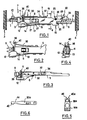
- an automatic adjustment spacer arranged in support by each of its ends between the cores 1 and 2 of two brake segments 3 and 4 of a motor vehicle drum brake, the automatic adjustment spacer being disposed in the vicinity of the clamping means (not shown) also disposed between the two segments 3 and 4 to apply the latter in spacing, in friction engagement against the brake drum (also not shown).
- the automatic adjustment spacer comprises a spacer body 5, intended to cooperate, at one of its ends, with the core 2 of the brake shoe 4 and with a hand brake lever 6 of the drum brake, and a screw and nut system 7 intended to cooperate, at one of its ends, with the core 1 of the other brake segment 3.
- the screw and nut system 7 comprises a screw 8 provided with a head 9 held in engagement , by a spring 10, with the core 1 of the brake segment 3, and a nut 11 engaged on the screw 8 and externally carrying a ratchet toothing intended to cooperate selectively with a pawl 12 secured to an elastic blade 13 mounted on the spacer body 5.
- the pawl 12 is normally kept apart from the teeth of the nut 11 by a rocker or adjustment square 14 freely engaged on the screw 8 and disposed between the nut 11 and the flat end face adjacent to the spacer body 5, as described in the document EP-A-0 077 726 mentioned above.
- the spacer body 5 is made in a single piece of casting, preferably in cast bronze.
- the spacer body 5 comprises an elongated main part in the form of a beam of substantially parallelepipedic section terminated, at one end, by an enlarged head 16 with a substantially square section, traversed longitudinally by a bore 17 extending, in the main part 15, beyond the end head 16, by a cylindrical part 17 of the same diameter, partially closed peripherally, that is to say having an open lateral portion 18 resulting from the difference in thickness between the main part 15 and the head d end 16.
- the elongated main part 15 ends, at its lower part (in the drawing), by a hook part 19 intended to receive the edge of the brake lever at hand 6 and defining, for the latter, a bottom forming a stop 20 and a lateral bearing face 21.
- the elongated main part 15 ends, at its upper part (in the drawing), by an extension wing 22 connects ordering with the face 21 of the hook part 19 by a shoulder 23 and forming a longitudinal contact face 24 for an adjacent face of the core 2 of the corresponding brake segment 4.
- extension wing 22 is connected at the upper part of the main elongated part 15 by a hook forming zone intended to receive a strand of a spring 26 hooked moreover to the core 2 of the brake segment 4 in order to urge the latter towards the shoulder 23.
- the underside 27 (in the drawing) of the elongated main part 15 of the spacer body 5 is substantially flat and has two lugs projecting outwards perpendicularly to this face 27 in the vicinity of the hook part 19 and intended to be received in corresponding holes in the elastic blade 13, the lugs having come directly from the foundry with the body spacer 5.
- the blade 13 is fixed to the spacer body 5 by crimping the ends of the pins.
- the bimetallic strip 30 consists of a bimetallic strip 30 fixed by one of its ends 32 to the spacer body 5 by crushing of protuberances forming lugs 34 coming from molding with the body.
- the bimetallic strip 30 has its face of greatest expansion adjacent to the upper part of the body 5 (if we consider the drawing). At ambient temperature, it extends parallel to the body 5 at a short distance from the latter.
- the free hook-shaped end 36 of the bimetallic strip 30 enters an opening 38 of an extension 40 of the plate of the adjustment bracket 14 as shown in FIG. 4.
- the extension 40 is slightly folded down relative to the plane of the brochure. This arrangement allows better hooking of the hook 36 on the upper edge of the opening 38 when the bimetallic strip is heated and takes the position in which it is shown in FIG. 2 with a view to locking the bracket forming the control lever.
- FIG. 5 shows a lever 14a and in FIG. 6 a bimetallic strip 30a according to a variant.
- the window 38a of the extension 40a comprises, at its upper part, a cutout 46 provided for receiving the lesser-width part 44 connecting the body of the bimetallic strip 30a to a head 42.
- the bimetallic strip according to this variant is more economical to manufacture than when it includes the hook 36.
- the spring (not shown) which urges the segments 3 and 4 towards each other, urges the spacer body 5 and the screw and nut system 7 towards each other, thereby pressing the plate of the adjustment bracket 14 resting, on the one hand against the flat end face of the head 16 of the spacer body 5 and against the adjacent nut 11.
- the arm of the bracket adjustment 14 releases the elastic blade 13 from the face 27 of the spacer body 5 and, consequently, the pawl 12 (integral with the blade 13 or articulated elastically on the latter) from the teeth of the nut 11.
- the segments 3 and 4 are biased away from one another, thus tending to separate the spacer body 5 from one another and the screw and nut system 7, which allows the plate of the adjustment bracket 14 to recover an inclined position relative to the screw 8 on which it is mounted and therefore the elastic blade 13 to resiliently approach the face 27 of the spacer body 5 by bringing the pawl 12 into engagement with the teeth of the nut 11, which tends to rotate the latter relative to the screw 8 until the blade 13 adopts its configuration of rest with respect to the spacer body 5.
- the two segments 3 and 4 move towards each other again, thereby tending to contract the spacer, which again causes the tilting of the plate of the adjustment bracket 14 to release the pawl 12 from the teeth of the nut 11.
Landscapes
- Engineering & Computer Science (AREA)
- General Engineering & Computer Science (AREA)
- Mechanical Engineering (AREA)
- Braking Arrangements (AREA)
- Fodder In General (AREA)
Applications Claiming Priority (2)
| Application Number | Priority Date | Filing Date | Title |
|---|---|---|---|
| FR8513906 | 1985-09-19 | ||
| FR8513906A FR2587428B1 (fr) | 1985-09-19 | 1985-09-19 | Entretoise a reglage automatique, a verrouillage thermique, pour frein a tambour |
Publications (2)
| Publication Number | Publication Date |
|---|---|
| EP0219384A1 true EP0219384A1 (de) | 1987-04-22 |
| EP0219384B1 EP0219384B1 (de) | 1990-02-07 |
Family
ID=9323061
Family Applications (1)
| Application Number | Title | Priority Date | Filing Date |
|---|---|---|---|
| EP86401984A Expired - Lifetime EP0219384B1 (de) | 1985-09-19 | 1986-09-10 | Strebe mit selbsttätiger Nachstellung und thermische Verriegelung für Trommelbremse |
Country Status (14)
| Country | Link |
|---|---|
| US (1) | US4729457A (de) |
| EP (1) | EP0219384B1 (de) |
| JP (1) | JPH076565B2 (de) |
| KR (1) | KR940007896B1 (de) |
| AU (1) | AU591927B2 (de) |
| BR (1) | BR8604593A (de) |
| DE (1) | DE3668962D1 (de) |
| ES (1) | ES2002178A6 (de) |
| FR (1) | FR2587428B1 (de) |
| HR (1) | HRP920586A2 (de) |
| IN (1) | IN167017B (de) |
| PT (1) | PT83380B (de) |
| TR (1) | TR23007A (de) |
| YU (1) | YU47042B (de) |
Cited By (1)
| Publication number | Priority date | Publication date | Assignee | Title |
|---|---|---|---|---|
| FR2713730A1 (fr) * | 1993-12-13 | 1995-06-16 | Alliedsignal Europ Services | Entretoise de réglage automatique pour frein à tambour. |
Families Citing this family (21)
| Publication number | Priority date | Publication date | Assignee | Title |
|---|---|---|---|---|
| FR2604230B1 (fr) * | 1986-09-24 | 1988-12-02 | Bendix France | Entretoise de reglage automatique pour frein a tambour et flan pour la realisation du corps d'une telle entretoise. |
| FR2610379B1 (fr) * | 1987-01-29 | 1989-04-21 | Bendix France | Frein a tambour a reglage automatique |
| FR2611011B1 (fr) * | 1987-02-12 | 1994-05-13 | Bendix France | Frein a tambour a reglage automatique verrouille a haute temperature |
| GB8905618D0 (en) * | 1989-03-11 | 1989-04-26 | Automotive Prod Plc | Automatic adjuster for drum brake |
| US5067596A (en) * | 1990-10-09 | 1991-11-26 | Allied Signal Inc. | Clip-on automatic adjuster strut lever for a drum brake |
| AU644492B2 (en) * | 1990-10-09 | 1993-12-09 | Allied-Signal Inc. | Clip-on automatic adjuster strut lever for a drum brake |
| US5484042A (en) * | 1991-04-04 | 1996-01-16 | Brake And Clutch Industries Australia Pty, Ltd. | Fluid pressure and mechanical drum brake actuator |
| GB9112350D0 (en) * | 1991-06-08 | 1991-07-31 | Gen Motors France | Drum brake and wear adjuster therefor |
| DE9208465U1 (de) * | 1992-06-25 | 1993-10-28 | Lucas Industries P.L.C., Solihull, West Midlands | Selbsttätige Nachstellvorrichtung für eine Bremse, insbesondere eine Trommelbremse |
| GB9224707D0 (en) * | 1992-11-25 | 1993-01-13 | Automotive Products Plc | Automatic adjuster for drum brake |
| JP3728574B2 (ja) * | 1997-06-11 | 2005-12-21 | 日清紡績株式会社 | ドラムブレーキのシュー間隙自動調整装置 |
| US6345702B1 (en) | 1998-02-19 | 2002-02-12 | Automotive Products (Italia) Spa | Brake adjusters |
| GB9803598D0 (en) * | 1998-02-21 | 1998-04-15 | Automotive Prod Italia | Brake adjusters |
| DE19858745A1 (de) * | 1998-12-18 | 2000-06-21 | Continental Teves Ag & Co Ohg | Trommelbremse mit thermischer Nachstellungsbegrenzung |
| IT1308764B1 (it) * | 1999-06-29 | 2002-01-10 | Maff S P A | Compensatore automatico del gioco per un freno a tamburo perautoveicoli |
| AUPQ558300A0 (en) * | 2000-02-11 | 2000-03-09 | Pbr Australia Pty Ltd | Adjuster strut |
| DE10121968A1 (de) * | 2001-01-17 | 2002-07-18 | Continental Teves Ag & Co Ohg | Nachstellvorrichtung einer Trommelbremse |
| GB0122436D0 (en) * | 2001-09-18 | 2001-11-07 | Automotive Products Uk Ltd | Brake adjusters |
| JP3953348B2 (ja) * | 2002-03-27 | 2007-08-08 | 日清紡績株式会社 | ドラムブレーキ |
| JP2003307241A (ja) * | 2002-04-16 | 2003-10-31 | Nisshinbo Ind Inc | シュー間隙自動調整装置 |
| ITTO20060478A1 (it) * | 2006-06-30 | 2008-01-01 | Raicam S P A | Ricuperatore automatico del gioco per un freno a tamburo per autoveicoli |
Citations (3)
| Publication number | Priority date | Publication date | Assignee | Title |
|---|---|---|---|---|
| US2570398A (en) * | 1948-03-15 | 1951-10-09 | Thermo Brakes Corp | Automatic adjusting mechanism for brakes |
| US4148380A (en) * | 1976-12-20 | 1979-04-10 | Tokico Ltd. | Automatic shoe clearance adjusting device in shoe drum brake |
| EP0077726A1 (de) * | 1981-10-19 | 1983-04-27 | Societe Anonyme D.B.A. | Trommelbremse und Strebenteil für eine derartige Bremse |
Family Cites Families (11)
| Publication number | Priority date | Publication date | Assignee | Title |
|---|---|---|---|---|
| GB471519A (en) * | 1936-02-06 | 1937-09-06 | Bendix Ltd | Improved automatic adjusting device for brakes |
| US2292017A (en) * | 1940-09-26 | 1942-08-04 | Thermo Brakes Corp | Brake adjuster |
| US3213970A (en) * | 1963-11-12 | 1965-10-26 | Bendix Corp | Automatic adjustor |
| GB1360974A (en) * | 1970-08-24 | 1974-07-24 | Girling Ltd | Internal shoe drum brakes |
| FR2285545A1 (fr) * | 1974-09-17 | 1976-04-16 | Dba | Dispositif de rattrapage d'usure sensible a la temperature pour frein a tambour |
| JPS5563024A (en) * | 1978-11-07 | 1980-05-12 | Tokico Ltd | Drum brake |
| US4385681A (en) * | 1979-05-21 | 1983-05-31 | Lucas Industries Limited | Drum brakes having automatic adjusters |
| GB2049077A (en) * | 1979-05-21 | 1980-12-17 | Lucas Industries Ltd | Automatic adjuster for drum brakes |
| US4243125A (en) * | 1979-09-21 | 1981-01-06 | Chrysler Corporation | Self-adjusting drum brake |
| US4503949A (en) * | 1982-11-01 | 1985-03-12 | Societe Anonyme D.B.A. | Drum brake and the spacer for such a brake |
| FR2570455B1 (fr) * | 1984-09-19 | 1986-12-05 | Bendix France | Entretoise de reglage automatique pour frein a tambour |
-
1985
- 1985-09-19 FR FR8513906A patent/FR2587428B1/fr not_active Expired
-
1986
- 1986-08-26 IN IN768/DEL/86A patent/IN167017B/en unknown
- 1986-09-03 US US06/903,168 patent/US4729457A/en not_active Expired - Lifetime
- 1986-09-10 EP EP86401984A patent/EP0219384B1/de not_active Expired - Lifetime
- 1986-09-10 DE DE8686401984T patent/DE3668962D1/de not_active Expired - Lifetime
- 1986-09-16 YU YU160786A patent/YU47042B/sh unknown
- 1986-09-16 PT PT83380A patent/PT83380B/pt not_active IP Right Cessation
- 1986-09-16 AU AU62753/86A patent/AU591927B2/en not_active Expired
- 1986-09-17 TR TR03/86A patent/TR23007A/xx unknown
- 1986-09-17 KR KR1019860007846A patent/KR940007896B1/ko not_active Expired - Lifetime
- 1986-09-17 JP JP61217371A patent/JPH076565B2/ja not_active Expired - Lifetime
- 1986-09-19 ES ES8602033A patent/ES2002178A6/es not_active Expired
- 1986-09-19 BR BR8604593A patent/BR8604593A/pt not_active IP Right Cessation
-
1992
- 1992-09-29 HR HRP920586AA patent/HRP920586A2/hr not_active Application Discontinuation
Patent Citations (3)
| Publication number | Priority date | Publication date | Assignee | Title |
|---|---|---|---|---|
| US2570398A (en) * | 1948-03-15 | 1951-10-09 | Thermo Brakes Corp | Automatic adjusting mechanism for brakes |
| US4148380A (en) * | 1976-12-20 | 1979-04-10 | Tokico Ltd. | Automatic shoe clearance adjusting device in shoe drum brake |
| EP0077726A1 (de) * | 1981-10-19 | 1983-04-27 | Societe Anonyme D.B.A. | Trommelbremse und Strebenteil für eine derartige Bremse |
Cited By (5)
| Publication number | Priority date | Publication date | Assignee | Title |
|---|---|---|---|---|
| FR2713730A1 (fr) * | 1993-12-13 | 1995-06-16 | Alliedsignal Europ Services | Entretoise de réglage automatique pour frein à tambour. |
| WO1995016864A1 (fr) * | 1993-12-13 | 1995-06-22 | Alliedsignal Europe Services Techniques | Entretoise de reglage automatique pour frein a tambour |
| TR28022A (tr) * | 1993-12-13 | 1996-01-02 | Alliedsignal Europ Services | Bir tamburlu fren icin otomatik ayarlanan germe cubugu . |
| AU677735B2 (en) * | 1993-12-13 | 1997-05-01 | Alliedsignal Europe Services Techniques | Automatic adjusting strut for drum brake |
| CN1046341C (zh) * | 1993-12-13 | 1999-11-10 | 联合信号欧洲技术服务公司 | 鼓式制动器的自动调整支杆 |
Also Published As
| Publication number | Publication date |
|---|---|
| TR23007A (tr) | 1989-01-10 |
| FR2587428A1 (fr) | 1987-03-20 |
| HRP920586A2 (hr) | 1994-04-30 |
| KR940007896B1 (ko) | 1994-08-27 |
| BR8604593A (pt) | 1987-05-26 |
| KR870003327A (ko) | 1987-04-16 |
| YU47042B (sh) | 1994-12-28 |
| AU6275386A (en) | 1987-03-26 |
| FR2587428B1 (fr) | 1987-11-27 |
| DE3668962D1 (de) | 1990-03-15 |
| YU160786A (en) | 1989-06-30 |
| EP0219384B1 (de) | 1990-02-07 |
| JPS6267336A (ja) | 1987-03-27 |
| ES2002178A6 (es) | 1988-07-16 |
| IN167017B (de) | 1990-08-18 |
| AU591927B2 (en) | 1989-12-21 |
| JPH076565B2 (ja) | 1995-01-30 |
| US4729457A (en) | 1988-03-08 |
| PT83380B (pt) | 1992-10-30 |
| PT83380A (fr) | 1986-10-01 |
Similar Documents
| Publication | Publication Date | Title |
|---|---|---|
| EP0219384A1 (de) | Strebe mit selbsttätiger Nachstellung und thermische Verriegelung für Trommelbremse | |
| FR2700742A1 (fr) | Moyen de blocage pour ajustement de tension de câble de frein de stationnement de véhicule. | |
| EP0276611A2 (de) | Selbsttätig nachstellende Trommelbremse | |
| FR2726615A1 (fr) | Dispositif d'actionnement mecanique pour frein a tambour | |
| EP0734496B1 (de) | Automatisch nachstellbare strebe für eine trommelbremse | |
| EP0186537B1 (de) | Scheibenbremse | |
| EP0278834B1 (de) | Trommelbremse mit selbsttätiger Nachstellung, verriegelt bei hohen Temperaturen | |
| EP0069657B1 (de) | Trommelbremse | |
| EP0178966B1 (de) | Strebe für automatische Nachstellvorrichtung für Trommelbremsen | |
| EP0531178B1 (de) | Selbsttätige Nachstellvorrichtung für einen Bremsmechanismus | |
| EP0061961B1 (de) | Trommelbremse mit selbsttätiger Nachstellung | |
| EP1115987B1 (de) | Automatische spielnachstellvorrichtung für trommelbremsen mit fallweiser verhinderung der nachstellung | |
| EP0262051A1 (de) | Schloss, insbesondere für Kraftfahrzeuge | |
| EP0003452B1 (de) | Trommelbremse | |
| EP0319358B1 (de) | Trommelbremse mit selbsttätiger Nachstellung | |
| EP0146444B1 (de) | Verankerung eines Verstrebungselementes, welches eine Einrichtung zur automatischen Regelung für ein Bremsbackensegment aufweist | |
| EP1072735A1 (de) | Verlegehilfevorrichtung zum Anbringen von Täfelung | |
| FR2786827A1 (fr) | Dispositif de rattrapage automatique de jeu, notamment sur cable de commande d'un frein de stationnement pour vehicule automobile | |
| FR2704661A1 (fr) | Dispositif de réglage de la position angulaire relative d'au moins deux pièces articulées entre elles selon un axe. | |
| EP0080951A1 (de) | Scheibenbremse | |
| EP1293371A1 (de) | Verbindungsanordnung und entsprechendes Kraftfahrzeug | |
| EP0288396A1 (de) | Dia-Wechselvorrichtung für Dia-Projektoren und Projektor mit einem solchen Mechanismus | |
| FR2541740A1 (fr) | Frein a tambour a reglage automatique | |
| FR2523043A1 (fr) | Dispositif de support de roulette notamment pour chariot de manutention | |
| EP0349368A1 (de) | Einstellbare Scheibenbremse |
Legal Events
| Date | Code | Title | Description |
|---|---|---|---|
| PUAI | Public reference made under article 153(3) epc to a published international application that has entered the european phase |
Free format text: ORIGINAL CODE: 0009012 |
|
| 17P | Request for examination filed |
Effective date: 19860919 |
|
| AK | Designated contracting states |
Kind code of ref document: A1 Designated state(s): DE GB IT SE |
|
| 17Q | First examination report despatched |
Effective date: 19880919 |
|
| GRAA | (expected) grant |
Free format text: ORIGINAL CODE: 0009210 |
|
| AK | Designated contracting states |
Kind code of ref document: B1 Designated state(s): DE GB IT SE |
|
| REF | Corresponds to: |
Ref document number: 3668962 Country of ref document: DE Date of ref document: 19900315 |
|
| GBT | Gb: translation of ep patent filed (gb section 77(6)(a)/1977) | ||
| ITF | It: translation for a ep patent filed | ||
| PLBE | No opposition filed within time limit |
Free format text: ORIGINAL CODE: 0009261 |
|
| STAA | Information on the status of an ep patent application or granted ep patent |
Free format text: STATUS: NO OPPOSITION FILED WITHIN TIME LIMIT |
|
| 26N | No opposition filed | ||
| ITTA | It: last paid annual fee | ||
| EAL | Se: european patent in force in sweden |
Ref document number: 86401984.9 |
|
| REG | Reference to a national code |
Ref country code: GB Ref legal event code: IF02 |
|
| PGFP | Annual fee paid to national office [announced via postgrant information from national office to epo] |
Ref country code: GB Payment date: 20050826 Year of fee payment: 20 |
|
| PG25 | Lapsed in a contracting state [announced via postgrant information from national office to epo] |
Ref country code: IT Free format text: LAPSE BECAUSE OF NON-PAYMENT OF DUE FEES;WARNING: LAPSES OF ITALIAN PATENTS WITH EFFECTIVE DATE BEFORE 2007 MAY HAVE OCCURRED AT ANY TIME BEFORE 2007. THE CORRECT EFFECTIVE DATE MAY BE DIFFERENT FROM THE ONE RECORDED. Effective date: 20050910 |
|
| PGFP | Annual fee paid to national office [announced via postgrant information from national office to epo] |
Ref country code: SE Payment date: 20050923 Year of fee payment: 20 |
|
| PGFP | Annual fee paid to national office [announced via postgrant information from national office to epo] |
Ref country code: DE Payment date: 20051118 Year of fee payment: 20 |
|
| PG25 | Lapsed in a contracting state [announced via postgrant information from national office to epo] |
Ref country code: GB Free format text: LAPSE BECAUSE OF EXPIRATION OF PROTECTION Effective date: 20060909 |
|
| REG | Reference to a national code |
Ref country code: GB Ref legal event code: PE20 |
|
| EUG | Se: european patent has lapsed | ||
| PGRI | Patent reinstated in contracting state [announced from national office to epo] |
Ref country code: IT Effective date: 20090401 |
|
| PGFP | Annual fee paid to national office [announced via postgrant information from national office to epo] |
Ref country code: IT Payment date: 20050923 Year of fee payment: 20 |