EP0219445B1 - Statoranordnung für einen Kompressor mit einem Innenring aus Verbundwerkstoff - Google Patents
Statoranordnung für einen Kompressor mit einem Innenring aus Verbundwerkstoff Download PDFInfo
- Publication number
- EP0219445B1 EP0219445B1 EP86630148A EP86630148A EP0219445B1 EP 0219445 B1 EP0219445 B1 EP 0219445B1 EP 86630148 A EP86630148 A EP 86630148A EP 86630148 A EP86630148 A EP 86630148A EP 0219445 B1 EP0219445 B1 EP 0219445B1
- Authority
- EP
- European Patent Office
- Prior art keywords
- vane
- stator assembly
- shroud
- cavity
- assembly according
- Prior art date
- Legal status (The legal status is an assumption and is not a legal conclusion. Google has not performed a legal analysis and makes no representation as to the accuracy of the status listed.)
- Expired
Links
- 239000002131 composite material Substances 0.000 title claims description 10
- 230000007423 decrease Effects 0.000 claims description 5
- 238000013016 damping Methods 0.000 claims description 3
- 239000007789 gas Substances 0.000 description 17
- 230000000712 assembly Effects 0.000 description 8
- 238000000429 assembly Methods 0.000 description 8
- 238000013461 design Methods 0.000 description 8
- 239000000463 material Substances 0.000 description 7
- 229920002379 silicone rubber Polymers 0.000 description 6
- 239000004945 silicone rubber Substances 0.000 description 6
- 238000010276 construction Methods 0.000 description 4
- 239000002184 metal Substances 0.000 description 4
- 238000001746 injection moulding Methods 0.000 description 3
- 239000004593 Epoxy Substances 0.000 description 2
- 239000004744 fabric Substances 0.000 description 2
- 239000000835 fiber Substances 0.000 description 2
- 238000000034 method Methods 0.000 description 2
- 229920005989 resin Polymers 0.000 description 2
- 239000011347 resin Substances 0.000 description 2
- KUBDPQJOLOUJRM-UHFFFAOYSA-N 2-(chloromethyl)oxirane;4-[2-(4-hydroxyphenyl)propan-2-yl]phenol Chemical compound ClCC1CO1.C=1C=C(O)C=CC=1C(C)(C)C1=CC=C(O)C=C1 KUBDPQJOLOUJRM-UHFFFAOYSA-N 0.000 description 1
- OKTJSMMVPCPJKN-UHFFFAOYSA-N Carbon Chemical compound [C] OKTJSMMVPCPJKN-UHFFFAOYSA-N 0.000 description 1
- XZMCDFZZKTWFGF-UHFFFAOYSA-N Cyanamide Chemical compound NC#N XZMCDFZZKTWFGF-UHFFFAOYSA-N 0.000 description 1
- 229920000271 Kevlar® Polymers 0.000 description 1
- 239000004677 Nylon Substances 0.000 description 1
- 239000004952 Polyamide Substances 0.000 description 1
- 239000004642 Polyimide Substances 0.000 description 1
- 239000004957 Zytel Substances 0.000 description 1
- 229920006102 Zytel® Polymers 0.000 description 1
- 239000000853 adhesive Substances 0.000 description 1
- 230000001070 adhesive effect Effects 0.000 description 1
- 238000002485 combustion reaction Methods 0.000 description 1
- 238000011161 development Methods 0.000 description 1
- 229920001971 elastomer Polymers 0.000 description 1
- 238000005516 engineering process Methods 0.000 description 1
- 239000003822 epoxy resin Substances 0.000 description 1
- 239000011152 fibreglass Substances 0.000 description 1
- 239000011521 glass Substances 0.000 description 1
- 229910002804 graphite Inorganic materials 0.000 description 1
- 239000010439 graphite Substances 0.000 description 1
- 238000003780 insertion Methods 0.000 description 1
- 230000037431 insertion Effects 0.000 description 1
- 238000004519 manufacturing process Methods 0.000 description 1
- 239000011159 matrix material Substances 0.000 description 1
- 239000007769 metal material Substances 0.000 description 1
- 238000005065 mining Methods 0.000 description 1
- 238000000465 moulding Methods 0.000 description 1
- 229920001778 nylon Polymers 0.000 description 1
- 239000004033 plastic Substances 0.000 description 1
- 229920002647 polyamide Polymers 0.000 description 1
- 229920000647 polyepoxide Polymers 0.000 description 1
- 229920000728 polyester Polymers 0.000 description 1
- 229920001721 polyimide Polymers 0.000 description 1
- 229920001296 polysiloxane Polymers 0.000 description 1
- 230000002028 premature Effects 0.000 description 1
- 229920000260 silastic Polymers 0.000 description 1
- 229920001187 thermosetting polymer Polymers 0.000 description 1
- 238000012546 transfer Methods 0.000 description 1
Images


Classifications
-
- F—MECHANICAL ENGINEERING; LIGHTING; HEATING; WEAPONS; BLASTING
- F01—MACHINES OR ENGINES IN GENERAL; ENGINE PLANTS IN GENERAL; STEAM ENGINES
- F01D—NON-POSITIVE DISPLACEMENT MACHINES OR ENGINES, e.g. STEAM TURBINES
- F01D9/00—Stators
- F01D9/02—Nozzles; Nozzle boxes; Stator blades; Guide conduits, e.g. individual nozzles
- F01D9/04—Nozzles; Nozzle boxes; Stator blades; Guide conduits, e.g. individual nozzles forming ring or sector
- F01D9/042—Nozzles; Nozzle boxes; Stator blades; Guide conduits, e.g. individual nozzles forming ring or sector fixing blades to stators
-
- Y—GENERAL TAGGING OF NEW TECHNOLOGICAL DEVELOPMENTS; GENERAL TAGGING OF CROSS-SECTIONAL TECHNOLOGIES SPANNING OVER SEVERAL SECTIONS OF THE IPC; TECHNICAL SUBJECTS COVERED BY FORMER USPC CROSS-REFERENCE ART COLLECTIONS [XRACs] AND DIGESTS
- Y02—TECHNOLOGIES OR APPLICATIONS FOR MITIGATION OR ADAPTATION AGAINST CLIMATE CHANGE
- Y02T—CLIMATE CHANGE MITIGATION TECHNOLOGIES RELATED TO TRANSPORTATION
- Y02T50/00—Aeronautics or air transport
- Y02T50/60—Efficient propulsion technologies, e.g. for aircraft
Definitions
- the present invention relates to gas turbine engines, and in particular, to compressor stator assemblies for gas turbine engines.
- a gas turbine engine includes a compressor section, a combustion section, and a turbine section, all circumscribed by an annular engine case.
- working medium gases move axially along annular gas flow path, through a series of rotor assemblies and stator assemblies.
- Each stator assembly includes a plurality of vanes which extend radially across the flow path.
- the outer ends of the vanes are attached either directly to the engine case, or to an outer stator shroud which is supported from the engine case.
- the case or outer stator shroud defines the outer boundary of the flow path.
- the inner ends of the vanes support an inner stator shroud or wall which defines the inner boundary of the flow path.
- Stator assembly components are typically metal structures; and in the forward section of the compressor, are subjected to relatively low operating temperatures.
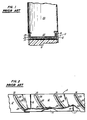
- circumferentially segmented, arcuate inner stator shroud sections are fabricated from a light weight plastic rather than metal, and are bolted together to from an annular inner stator shroud.
- the radially inner and outer ends of the stator vanes are specially shaped, and engage dove-tail type slots in the inner shroud sections and engine case, respectively.
- a radially inner stator shroud assembly 10 comprises a plurality of arcuate stator segments 12 fabricated from a composite material, which are adhesively bonded to arcuate, circumferentially segmented bands 14. Each band 14 overlies the interface 16 between adjacent, circumferentially disposed segments 12.
- the inner shroud assembly 10 also includes a labyrinth rub strip 18 attached to the radially inwardly facing side of each band 14. The rub strip 18 overlies the interface 19 between adjacent bands 14.
- Each stator segment 12 includes a plurality of arcuate, circumferentially spaced apart cavities 20 for receiving the inner end 22 of each stator vane 24.
- the inner end 22 of each stator vane 24 is surrounded by a silicone rubber vibration damping material 26 which is bonded to the walls of the cavity; the silicone rubber 26 secures each vane end 22 within its cavity 20.
- the outer end of each vane 24 is rigidly attached to the stator outer shroud (not shown).
- the circumferential width of each cavity 20 is constant, from the cavity forward end 28 to the cavity rearward end 30, and the depth of each cavity 20 increases from its forward end 28 to its rearward end 30.
- composite is intended to mean a material characterized by a distribution of fibers such as glass, graphite, or silicone carbide, within a matrix of cured epoxy or any of the known polyesters or polyimides.
- GB-A 2 110 768 Another prior art fixing for compressor stator vanes is disclosed in GB-A 2 110 768.
- the inner ends of the stator vanes have one or more flanges projecting from the vanes into elastomer-lined channels in the shroud rings.
- the object of the invention is to provide a light weight and easy to assemble compressor stator structure.
- stator assembly according to the present invention is that assembly of the stator structure is easier than assembly of stator structures of the prior art.
- the inner support structure has markedly improved hoop strength as compared to stator assemblies of the prior art, in which the inner shroud is circumferentially segmented.
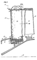
- the compressor section 40 includes a stator assembly 42 and an axially adjacent rotor assembly 44.
- the rotor assembly 44 includes a disk 46 which rotates about the engine axis 48, and a circumferential row of blades 50 attached to the disk 46 in any conventional manner.
- the blades 50 extend radially outwardly from the disk 46, and across a flow path 52 of working medium gases.
- the stator assembly 42 includes an outer vane support structure 54 and a circumferential row of vanes 56 which are attached to the structure 54 and which extend radially inwardly therefrom.
- the radially inwardly facing surface 58 of the outer structure 54 defines the outer boundary of the flow path 52.
- the stator assembly 42 also includes an inner vane support structure 60. As the gases move through the stator assembly 42, the radially outwardly facing surface of the inner structure 60 defines the inner boundary of the flow path 52.
- the inner structure 60 includes a labyrinth type seal 62 which is engageable by knife edges 64 integral with the disk 46.
- Each stator vane 56 has radially opposed outer and inner ends, 66, 68, respectively.
- the outer end 66 of each vane 56 extends through a slot (not shown, in the outer structure 54. Adjacent to each slot are a pair of closely spaced brackets 70 which are attached to the structure outer surface 72 by rivets 74.
- the outer end 66 of one vane 56 is disposed between each pair of brackets 70, and is attached to the brackets 70 by rivets 76. In this manner, the outer end 66 of each vane 56 is rigidly attached to the outer structure 54.
- the vanes 56 extends radially across the gas flow path 52, and as described hereinbelow, the vane inner ends 68 support the inner vane support structure 60.
- the components of the inner vane support structure 60 are fabricated from composite materials having a high strength-to-weight ratio, which results in significant weight savings as compared to stator assemblies which utilize metallic materials.
- the inner support structure 60 comprises a one piece inner ring 78, and a plurality of arcuate, circumferentially segmented shroud sections 80 which surround and are attached to the inner ring 78.
- Each shroud section 80 has a plurality of circumferentially spaced apart cavities 82, and each cavity 82 receives and retains therein one vane inner end 68. As will be described hereinbelow, there are slight geometric differences between the cavities 82 in each shroud section 80.
- the inner ring 78 has an axially extending forward land and rearward land 84, 86, respectively.
- the forward land 84 is inclined relative to the engine axis of rotation 48, while the rearward land 54 is substantially cylindrical.
- the forward land 84 has a radially outwardly facing surface 88, and the rearward land 86 has a radially outwardly facing surface 90.
- the ring 78 has a radially inwardly extending, annular V-shaped channel 92.
- the channel 92 has a forward leg 94 and a rearward leg 96, both legs 94, 96 extending radially inwardly in opposite axial directions towards a channel vertex 98.
- the inner vane support structure 60 has markedly improved hoop strength as compared to the segmented shroud assemblies of the prior art. Also, the cross sectional shape of the gas path inner boundary is precisely circular, which is aerodynamically efficient.
- the inner ring 78 is a laminated structure, comprising a plurality of polyamide fabric plies impregnated with the thermosetting epoxy resin.
- the specific materials which may be used to fabricate the inner ring 78 are AMS 3902 style 285 Kevlar@ fabric, available from Burlington Glass Fabrics, Altavista, VA, and Epon 826 resin, available from Shell Development Corp., Houston, TX.
- the inner ring 78 is fabricated by the dry lay- up/resin transfer process, common in the art.
- each shroud section 80 has a corrugated structure, i.e., an alternating series of ridges 100 and cavities 82. Because of the corrugated structure, the radially outwardly facing surface 102 of each ridge 100 defines the gas path surface of each shroud section 80.
- wall sections 104 define the base 106 of each cavity 82.
- the radially inwardly facing surface 108 of each wall section 104 includes a radially inwardly and circumferentially extending tang 110.
- the cavity depth (measured from the gas path surface 102 to the base 106) increases in the rearward axial direction.
- Arcuate, axially extending sidewalls 112 define the circumferential boundaries of the cavities 82, and forward and rearward endwalls 114, 116, respectively, define the axial boundaries of the cavities 82.
- the radial height of the sidewalls 112 is greater than the height of the rearward endwall 116 where the walls 112, 116 meet.
- the degree of curvature of the cavity sidewalls 112 is similar to the degree of curvature of the airfoil shaped vane inner ends 68, although the axial width of each cavity 82 is greater than the thickness of each vane end 68, and the cavity width decreases in the rearward axial direction.
- the cavities 82 are specially shaped so as to easily receive and retain therein each vane inner end 68, and to simplify the fabrication of the shroud sections 80.
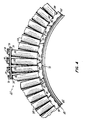
- Each shroud section 80 is fabricated from a chopped fiberglass reinforced nylon composite, preferably 33% fibers by weight, using injection molding techniques. Such material is available as RF-1006 (LNP Corp., Malvern, PA) or Zytel 70G33BK (E.I. Dupont Co., Inc., Wilmington, DE). To facilitate removal of each shroud section 80 from the injection molding apparatus after the shroud section 80 has been fabricated, the design of the cavities 82 is as described hereinbelow. Each shroud section 80 has a centerline 122 (Fig. 7) passing through the central cavity 82 of the shroud section 80, which preferably has an odd number of cavities 82. The centerline 122 also passes through the center of curvature 124 of the shroud section 80.
- Each cavity 82 preferably has its sidewall 112 nearest the centerline 122 parallel to the centerline 122.
- the other sidewall 112 of each cavity 82 diverges radially outwardly away from its opposing cavity sidewall 112, and preferably is parallel to a radial line passing through the shroud section center of curvature 124. Because of the construction of each shroud section 80, and in particular the shape of the cavities 82, at the completion of the injection molding process the molding dies can be moved apart along a line parallel to the section centerline 122 in order to remove the shroud section 80 molded therebetween.
- Each shroud section 80 is bonded to the inner ring 78 using an epoxy film adhesive such as FM 250K (American Cyanamid Corp., Havre de Grace, MD) or AF 3109-2K (Minnesota Mining and Manufacturing Co., St. Paul, MN).
- FM 250K American Cyanamid Corp., Havre de Grace, MD
- AF 3109-2K Minnesota Mining and Manufacturing Co., St. Paul, MN.
- the axially facing forward endwall 114 of the shroud section 80 is bonded to the ring forward leg 94; the axially rearward facing portion of the tang 110 is bonded to the rearward leg 96; and the portion of the shroud section to the rear of the tang 110 is bonded to the ring rearward land 86.
- each shroud section 80 is bonded to the inner ring 78 on three distinct planes, which maintains the shroud section 80 in a fixed position more securely than constructions of the prior art.
- the circumferential ends 118, 120 of each shroud section 80 define portions of cavity 82 which mate with corresponding portions of adjacent shroud sections 80 to form complete cavities 82 upon assembly, Fig. 4.
- each stator vane 56 extends radially inwardly from the outer support structure 54.
- the length of each vane 56 is chosen so that in the assembled stator structure 40, the vane inner end 68 is slightly spaced from the base 106 of its respective cavity 82, Figs. 3 and 7. Also, since the cavities 82 are longer and wider than the vane inner ends 68, each vane end 68 is slightly spaced from its respective axially facing cavity endwalls 114, 116 and circumferentially facing cavity sidewalls 112.
- each vane 56 is inserted radially inwardly through a slot (not shown) in the outer vane support structure 54, and positioned within its respective shroud section cavity 82. Fixturing devices are utilized to locate and hold each vane 56 at its correct position, and each vane outer end 66 is riveted to the outer structure 54 as described above.
- the datum line 126 of each stator vane 56 lies on a radial line which passes through the shroud section center of curvature 124.
- a vibration damping silicone rubber material 128 is added to each cavity 82 to retain each vane inner end 68 therein.
- the silicone rubber 128 bonds to the cavity walls, and completely fills each cavity 82, surrounding and bonding to each vane end 68.
- the rubber 128 is substantially flush with the shroud outer, gas path surface 102, and with the shroud rear endwall 116.
- Representative of silicone rubber materials which may be used are Silastic J (Dow Corning Corp., Elizabethtown, KY); Dapocast 37 (D Aircraft Products, Anaheim, CA); and Eccosil 1478-2 (Emerson & Cummings, Inc., Canton, MA).
- the shape of the cavities may be altered to meet the specific requirements of the stator assembly 42.
- the cavities 130 extend from one axial end of the shroud section 132 to the other end of the shroud section 132, and have no axially facing boundaries.
- the cavities 130 are defined only by circumferentially facing sidewalls 134 and the radially facing wall 136.
- the shroud sections 132 are considerably less rigid, and can be more easily bent in a radial direction than the sections 48 shown in Figs. 5-6. Such a design could be used if flexibility were required to aid in assembly of the stator structure.
- the cavities 130 need not be arcuate; they may also be straight, as shown in Fig.
- the cavities are tapered, i.e., the cavity width decreases in the rearward axial direction. It is believed that this feature would limit the movement of the inner support structure in the forward axial direction during an aerodynamic pressure disturbance, or surge. Since the vanes are rigidly attached to the outer support structure, axial movement of the vanes will be limited during a pressure disturbance. Also, since the cavities are tapered, movement of the shroud sections 132, and the ring they are bonded to, will be limited. This is because the narrow, rearward portion of each cavity 130 cannot move axially forward, past the wider mass of silicone rubber which is believed will remain stationary, bonded to the vane inner end.
Landscapes
- Engineering & Computer Science (AREA)
- Mechanical Engineering (AREA)
- General Engineering & Computer Science (AREA)
- Structures Of Non-Positive Displacement Pumps (AREA)
- Turbine Rotor Nozzle Sealing (AREA)
Claims (12)
Applications Claiming Priority (2)
| Application Number | Priority Date | Filing Date | Title |
|---|---|---|---|
| US06/781,606 US4655682A (en) | 1985-09-30 | 1985-09-30 | Compressor stator assembly having a composite inner diameter shroud |
| US781606 | 1985-09-30 |
Publications (2)
| Publication Number | Publication Date |
|---|---|
| EP0219445A1 EP0219445A1 (de) | 1987-04-22 |
| EP0219445B1 true EP0219445B1 (de) | 1989-06-07 |
Family
ID=25123312
Family Applications (1)
| Application Number | Title | Priority Date | Filing Date |
|---|---|---|---|
| EP86630148A Expired EP0219445B1 (de) | 1985-09-30 | 1986-09-29 | Statoranordnung für einen Kompressor mit einem Innenring aus Verbundwerkstoff |
Country Status (4)
| Country | Link |
|---|---|
| US (1) | US4655682A (de) |
| EP (1) | EP0219445B1 (de) |
| JP (1) | JPH0713444B2 (de) |
| DE (1) | DE3663838D1 (de) |
Cited By (2)
| Publication number | Priority date | Publication date | Assignee | Title |
|---|---|---|---|---|
| WO2012125084A1 (en) * | 2011-03-14 | 2012-09-20 | Volvo Aero Corporation | Gas turbine structure |
| BE1030361B1 (fr) * | 2022-03-17 | 2023-10-16 | Safran Aero Boosters | Coque d'amortissement pour turbomachine, assemblage comprenant la coque et une aube, ensemble rotatif, compresseur et procede de fabrication associe |
Families Citing this family (66)
| Publication number | Priority date | Publication date | Assignee | Title |
|---|---|---|---|---|
| US4907946A (en) * | 1988-08-10 | 1990-03-13 | General Electric Company | Resiliently mounted outlet guide vane |
| US4986737A (en) * | 1988-12-29 | 1991-01-22 | General Electric Company | Damped gas turbine engine airfoil row |
| US5074752A (en) * | 1990-08-06 | 1991-12-24 | General Electric Company | Gas turbine outlet guide vane mounting assembly |
| US5226789A (en) * | 1991-05-13 | 1993-07-13 | General Electric Company | Composite fan stator assembly |
| FR2680384B1 (fr) * | 1991-08-13 | 1995-03-10 | Plastiremo | Couronne d'aubage a montage simplifie et aube pour sa realisation. |
| US5180282A (en) * | 1991-09-27 | 1993-01-19 | General Electric Company | Gas turbine engine structural frame with multi-yoke attachment of struts to outer casing |
| FR2685383B1 (fr) * | 1991-12-18 | 1994-02-11 | Snecma | Bras structural du carter d'une turbomachine. |
| FR2697285B1 (fr) * | 1992-10-28 | 1994-11-25 | Snecma | Système de verrouillage d'extrémités d'aubes. |
| JP3631271B2 (ja) * | 1993-11-19 | 2005-03-23 | ユナイテッド テクノロジーズ コーポレイション | インナーシュラウド一体型ステータベーン構造 |
| US5380155A (en) * | 1994-03-01 | 1995-01-10 | United Technologies Corporation | Compressor stator assembly |
| US5586864A (en) * | 1994-07-27 | 1996-12-24 | General Electric Company | Turbine nozzle diaphragm and method of assembly |
| US5411370A (en) * | 1994-08-01 | 1995-05-02 | United Technologies Corporation | Vibration damping shroud for a turbomachine vane |
| US5690469A (en) * | 1996-06-06 | 1997-11-25 | United Technologies Corporation | Method and apparatus for replacing a vane assembly in a turbine engine |
| US6409472B1 (en) * | 1999-08-09 | 2002-06-25 | United Technologies Corporation | Stator assembly for a rotary machine and clip member for a stator assembly |
| US6343912B1 (en) * | 1999-12-07 | 2002-02-05 | General Electric Company | Gas turbine or jet engine stator vane frame |
| DE60026687T2 (de) * | 2000-12-06 | 2006-11-09 | Techspace Aero S.A. | Statorstufe eines Verdichters |
| US6619917B2 (en) * | 2000-12-19 | 2003-09-16 | United Technologies Corporation | Machined fan exit guide vane attachment pockets for use in a gas turbine |
| US20030127924A1 (en) * | 2002-01-08 | 2003-07-10 | Pieter Van Dine | Composite canning arrangement for motors |
| GB2388161A (en) * | 2002-05-02 | 2003-11-05 | Rolls Royce Plc | Gas turbine engine compressor casing |
| DE10353810A1 (de) * | 2003-11-17 | 2005-06-23 | Rolls-Royce Deutschland Ltd & Co Kg | Innendeckband für die Statorschaufeln des Verdichters einer Gasturbine |
| DE102004001393A1 (de) * | 2004-01-09 | 2005-08-04 | Mtu Aero Engines Gmbh | Vorrichtung zur Aufhängung von Gaskanalelementen |
| US7950899B2 (en) * | 2005-05-31 | 2011-05-31 | United Technologies Corporation | Modular fan inlet case |
| USRE43928E1 (en) | 2005-06-28 | 2013-01-15 | United Technologies Corporation | Borescope inspection port device for gas turbine engine and gas turbine engine using same |
| US7458768B2 (en) * | 2005-06-28 | 2008-12-02 | United Technologies Corporation | Borescope inspection port device for gas turbine engine and gas turbine engine using same |
| US7413400B2 (en) * | 2005-09-12 | 2008-08-19 | Pratt & Whitney Canada Corp. | Vane assembly with grommet |
| US7530782B2 (en) * | 2005-09-12 | 2009-05-12 | Pratt & Whitney Canada Corp. | Foreign object damage resistant vane assembly |
| GB2434182A (en) * | 2006-01-11 | 2007-07-18 | Rolls Royce Plc | Guide vane arrangement for a gas turbine engine |
| USRE48123E1 (en) * | 2006-08-09 | 2020-07-28 | Asset Integrity Management Solutions, L.L.C. | Twin fin fairing |
| US7337742B1 (en) * | 2006-08-09 | 2008-03-04 | Viv Suppression, Inc. | Twin fin fairing |
| US20090022579A1 (en) * | 2007-07-17 | 2009-01-22 | Schlichting Kevin W | Burn resistant organic matrix composite material |
| US7980813B2 (en) * | 2007-08-13 | 2011-07-19 | United Technologies Corporation | Fan outlet guide vane shroud insert repair |
| FR2922950B1 (fr) * | 2007-10-31 | 2014-05-09 | Snecma | Cartouche de materiau abradable |
| GB2455785B (en) * | 2007-12-21 | 2009-11-11 | Rolls Royce Plc | Annular component |
| EP2075415B1 (de) * | 2007-12-27 | 2016-10-19 | Techspace Aero | Ringstruktur des Stators in leichterer Ausführung für das Triebwerk eines Luftfahrzeugs |
| US8500394B2 (en) | 2008-02-20 | 2013-08-06 | United Technologies Corporation | Single channel inner diameter shroud with lightweight inner core |
| FR2928963B1 (fr) * | 2008-03-19 | 2017-12-08 | Snecma | Distributeur de turbine pour une turbomachine. |
| EP2202264B1 (de) | 2008-12-24 | 2018-04-18 | Safran Aero Boosters SA | Herstellungsverfahren durch Formung eines Strukturelements einer Maschine mit Abrieboberfläche |
| EP2339120B1 (de) * | 2009-12-22 | 2015-07-08 | Techspace Aero S.A. | Leitschaufelstufe einer Strömungsmaschine und zugehöriger Verdichter |
| US8734089B2 (en) | 2009-12-29 | 2014-05-27 | Rolls-Royce Corporation | Damper seal and vane assembly for a gas turbine engine |
| EP2402615B1 (de) | 2010-06-29 | 2015-08-12 | Techspace Aero S.A. | Leitschaufelbaugruppe |
| US20120082556A1 (en) * | 2010-09-30 | 2012-04-05 | Enzo Macchia | Nanocrystalline metal coated composite airfoil |
| US20120082553A1 (en) * | 2010-09-30 | 2012-04-05 | Andreas Eleftheriou | Metal encapsulated stator vane |
| US9587645B2 (en) | 2010-09-30 | 2017-03-07 | Pratt & Whitney Canada Corp. | Airfoil blade |
| US9429029B2 (en) | 2010-09-30 | 2016-08-30 | Pratt & Whitney Canada Corp. | Gas turbine blade and method of protecting same |
| US8696311B2 (en) | 2011-03-29 | 2014-04-15 | Pratt & Whitney Canada Corp. | Apparatus and method for gas turbine engine vane retention |
| EP2586989B1 (de) | 2011-10-27 | 2015-04-29 | Techspace Aero S.A. | Koinjizierter Verbundring eines Kompressors eines axialen Turbotriebwerks |
| US9427835B2 (en) | 2012-02-29 | 2016-08-30 | Pratt & Whitney Canada Corp. | Nano-metal coated vane component for gas turbine engines and method of manufacturing same |
| US11035238B2 (en) | 2012-06-19 | 2021-06-15 | Raytheon Technologies Corporation | Airfoil including adhesively bonded shroud |
| EP2735706B8 (de) * | 2012-11-21 | 2016-12-07 | Safran Aero Booster S.A. | Gleichrichter mit Laufradschaufeln eines Kompressors eines axialen Turbotriebwerks, und Herstellungsverfahren |
| EP2735707B1 (de) * | 2012-11-27 | 2017-04-05 | Safran Aero Boosters SA | Leitrad einer axialen Turbomaschine mit segmentiertem Innendeckband und zugehöriger Verdichter |
| US9840929B2 (en) * | 2013-05-28 | 2017-12-12 | Pratt & Whitney Canada Corp. | Gas turbine engine vane assembly and method of mounting same |
| EP3004560B1 (de) | 2013-06-04 | 2018-11-07 | United Technologies Corporation | Schaufelanordnung mit zwei- und dreidimensionalen anordnungen endloser fasern |
| US9206700B2 (en) * | 2013-10-25 | 2015-12-08 | Siemens Aktiengesellschaft | Outer vane support ring including a strong back plate in a compressor section of a gas turbine engine |
| WO2015077011A1 (en) | 2013-11-19 | 2015-05-28 | United Technologies Corporation | Multi-element inner shroud extension for a turbo-machine |
| GB201412960D0 (en) * | 2014-07-22 | 2014-09-03 | Rolls Royce Plc | Vane assembly |
| BE1023367B1 (fr) * | 2015-08-19 | 2017-02-20 | Safran Aero Boosters S.A. | Fixation de virole interne de compresseur de turbomachine axiale |
| CN108472888B (zh) * | 2015-10-30 | 2021-04-06 | 米其林集团总公司 | 用于非充气式车轮的辐条制造 |
| USD802423S1 (en) | 2016-01-15 | 2017-11-14 | Owens-Brockway Glass Container Inc. | Container |
| US10472979B2 (en) * | 2016-08-18 | 2019-11-12 | United Technologies Corporation | Stator shroud with mechanical retention |
| US10415592B2 (en) * | 2016-10-21 | 2019-09-17 | United Technologies Corporation | Shroud for gas turbine engine |
| US10378383B2 (en) * | 2017-01-26 | 2019-08-13 | General Electric Company | Alignment apparatus for coupling diaphragms of turbines |
| US10900364B2 (en) * | 2017-07-12 | 2021-01-26 | Raytheon Technologies Corporation | Gas turbine engine stator vane support |
| US11898450B2 (en) | 2021-05-18 | 2024-02-13 | Rtx Corporation | Flowpath assembly for gas turbine engine |
| US11781432B2 (en) | 2021-07-26 | 2023-10-10 | Rtx Corporation | Nested vane arrangement for gas turbine engine |
| CN116677464A (zh) * | 2023-06-27 | 2023-09-01 | 南京航空航天大学 | 适用于小涵道比发动机的复材静子叶片扇形组件结构 |
| CN121654488A (zh) * | 2026-02-05 | 2026-03-13 | 中国航发湖南动力机械研究所 | 一种带包容机匣的复合材料静子叶片环 |
Family Cites Families (16)
| Publication number | Priority date | Publication date | Assignee | Title |
|---|---|---|---|---|
| DE967089C (de) * | 1940-12-21 | 1957-10-03 | Kuehnle Kopp Kausch Ag | Auswechselbare Axialleitapparat-Beschaufelung von Geblaesen, Pumpen u. dgl. |
| GB789733A (en) * | 1954-03-22 | 1958-01-29 | Rolls Royce | Improvements in or relating to structural elements for axial-flow compressors or turbines or the like machines |
| DE1213423B (de) * | 1960-06-04 | 1966-03-31 | Maschf Augsburg Nuernberg Ag | Befestigung der Schaufeln eines Leitschaufel-kranzes einer Stroemungsmaschine am Leitschaufeltraeger mittels gummielastischer Elemente |
| US3442442A (en) * | 1966-12-02 | 1969-05-06 | Gen Electric | Mounting of blades in an axial flow compressor |
| US3849023A (en) * | 1973-06-28 | 1974-11-19 | Gen Electric | Stator assembly |
| CS174516B1 (de) * | 1974-09-26 | 1977-04-29 | ||
| US3957391A (en) * | 1975-03-25 | 1976-05-18 | United Technologies Corporation | Turbine cooling |
| FR2321616A1 (fr) * | 1975-08-21 | 1977-03-18 | Snecma | Perfectionnements a la fixation des aubes statoriques d'une soufflante ou d'un compresseur a flux axial |
| FR2404102A1 (fr) * | 1977-09-27 | 1979-04-20 | Snecma | Couronne d'aubage fixe pour turbomachine axiale et son procede de realisation |
| JPS55161029U (de) * | 1979-05-08 | 1980-11-19 | ||
| FR2474395A1 (fr) * | 1980-01-28 | 1981-07-31 | Aerospatiale | Procede de fabrication d'un element flexible et torsible et elements obtenus selon ce procede |
| US4417854A (en) * | 1980-03-21 | 1983-11-29 | Rockwell International Corporation | Compliant interface for ceramic turbine blades |
| GB2084261A (en) * | 1980-09-30 | 1982-04-07 | Rolls Royce | Mounting compressor stator blades |
| GB2110768A (en) * | 1981-12-01 | 1983-06-22 | Rolls Royce | Fixings for stator vanes |
| US4422827A (en) * | 1982-02-18 | 1983-12-27 | United Technologies Corporation | Blade root seal |
| GB2115883B (en) * | 1982-02-26 | 1986-04-30 | Gen Electric | Turbomachine airfoil mounting assembly |
-
1985
- 1985-09-30 US US06/781,606 patent/US4655682A/en not_active Expired - Lifetime
-
1986
- 1986-09-29 DE DE8686630148T patent/DE3663838D1/de not_active Expired
- 1986-09-29 EP EP86630148A patent/EP0219445B1/de not_active Expired
- 1986-09-30 JP JP61233130A patent/JPH0713444B2/ja not_active Expired - Lifetime
Cited By (3)
| Publication number | Priority date | Publication date | Assignee | Title |
|---|---|---|---|---|
| WO2012125084A1 (en) * | 2011-03-14 | 2012-09-20 | Volvo Aero Corporation | Gas turbine structure |
| US9435215B2 (en) | 2011-03-14 | 2016-09-06 | Gkn Aerospace Sweden Ab | Gas turbine structure |
| BE1030361B1 (fr) * | 2022-03-17 | 2023-10-16 | Safran Aero Boosters | Coque d'amortissement pour turbomachine, assemblage comprenant la coque et une aube, ensemble rotatif, compresseur et procede de fabrication associe |
Also Published As
| Publication number | Publication date |
|---|---|
| JPS6285103A (ja) | 1987-04-18 |
| US4655682A (en) | 1987-04-07 |
| EP0219445A1 (de) | 1987-04-22 |
| DE3663838D1 (en) | 1989-07-13 |
| JPH0713444B2 (ja) | 1995-02-15 |
Similar Documents
| Publication | Publication Date | Title |
|---|---|---|
| US4655682A (en) | Compressor stator assembly having a composite inner diameter shroud | |
| US3037742A (en) | Compressor turbine | |
| EP0654586B1 (de) | Leitschaufelsegment | |
| US3836282A (en) | Stator vane support and construction thereof | |
| US3326523A (en) | Stator vane assembly having composite sectors | |
| JP5528721B2 (ja) | ケーシングとロータとの接触時の不安定性を防止するための装置を含むターボ機械のケーシング | |
| US4659285A (en) | Turbine cover-seal assembly | |
| US8511980B2 (en) | Segmented ceramic matrix composite turbine airfoil component | |
| US4832568A (en) | Turbomachine airfoil mounting assembly | |
| US3708242A (en) | Supporting structure for the blades of turbomachines | |
| US4264271A (en) | Impeller shroud of a centrifugal compressor | |
| US8636466B2 (en) | Segmented composite inner ferrule and segment of diffuser of axial compressor | |
| US4531362A (en) | Aerodynamic damping of vibrations in rotor blades | |
| US5263823A (en) | Gas turbine engine impeller having an annular collar platform | |
| US3694104A (en) | Turbomachinery blade | |
| US7186079B2 (en) | Turbine engine disk spacers | |
| US2999668A (en) | Self-balanced rotor blade | |
| JP3628328B2 (ja) | 圧縮機のステータアッセンブリ | |
| CA1324765C (en) | Turbine blade with integral shroud and method of assembling the blades in a circular array | |
| GB1385968A (en) | Support structures for turbo-machine blades | |
| GB2245032A (en) | Turbine blade inner end attachment structure | |
| JPH0425408B2 (de) | ||
| CA2876147A1 (en) | Aerofoil array for a gas turbine with anti fluttering means | |
| JP2807884B2 (ja) | 回転子組立体 | |
| US9739163B2 (en) | Strip for abradable in a compressor turbine |
Legal Events
| Date | Code | Title | Description |
|---|---|---|---|
| PUAI | Public reference made under article 153(3) epc to a published international application that has entered the european phase |
Free format text: ORIGINAL CODE: 0009012 |
|
| AK | Designated contracting states |
Kind code of ref document: A1 Designated state(s): DE FR GB |
|
| 17P | Request for examination filed |
Effective date: 19870922 |
|
| 17Q | First examination report despatched |
Effective date: 19880321 |
|
| GRAA | (expected) grant |
Free format text: ORIGINAL CODE: 0009210 |
|
| AK | Designated contracting states |
Kind code of ref document: B1 Designated state(s): DE FR GB |
|
| ET | Fr: translation filed | ||
| REF | Corresponds to: |
Ref document number: 3663838 Country of ref document: DE Date of ref document: 19890713 |
|
| PLBE | No opposition filed within time limit |
Free format text: ORIGINAL CODE: 0009261 |
|
| STAA | Information on the status of an ep patent application or granted ep patent |
Free format text: STATUS: NO OPPOSITION FILED WITHIN TIME LIMIT |
|
| 26N | No opposition filed | ||
| REG | Reference to a national code |
Ref country code: GB Ref legal event code: IF02 |
|
| PGFP | Annual fee paid to national office [announced via postgrant information from national office to epo] |
Ref country code: GB Payment date: 20050809 Year of fee payment: 20 |
|
| PGFP | Annual fee paid to national office [announced via postgrant information from national office to epo] |
Ref country code: FR Payment date: 20050902 Year of fee payment: 20 |
|
| PGFP | Annual fee paid to national office [announced via postgrant information from national office to epo] |
Ref country code: DE Payment date: 20050930 Year of fee payment: 20 |
|
| REG | Reference to a national code |
Ref country code: GB Ref legal event code: PE20 |
|
| PG25 | Lapsed in a contracting state [announced via postgrant information from national office to epo] |
Ref country code: GB Free format text: LAPSE BECAUSE OF EXPIRATION OF PROTECTION Effective date: 20060928 |