EP0219471A2 - Anordnung in einer Mischmaschine - Google Patents
Anordnung in einer Mischmaschine Download PDFInfo
- Publication number
- EP0219471A2 EP0219471A2 EP86850238A EP86850238A EP0219471A2 EP 0219471 A2 EP0219471 A2 EP 0219471A2 EP 86850238 A EP86850238 A EP 86850238A EP 86850238 A EP86850238 A EP 86850238A EP 0219471 A2 EP0219471 A2 EP 0219471A2
- Authority
- EP
- European Patent Office
- Prior art keywords
- mixing
- particles
- arrangement
- mixing machine
- fog
- Prior art date
- Legal status (The legal status is an assumption and is not a legal conclusion. Google has not performed a legal analysis and makes no representation as to the accuracy of the status listed.)
- Granted
Links
Images

Classifications
-
- B—PERFORMING OPERATIONS; TRANSPORTING
- B29—WORKING OF PLASTICS; WORKING OF SUBSTANCES IN A PLASTIC STATE IN GENERAL
- B29B—PREPARATION OR PRETREATMENT OF THE MATERIAL TO BE SHAPED; MAKING GRANULES OR PREFORMS; RECOVERY OF PLASTICS OR OTHER CONSTITUENTS OF WASTE MATERIAL CONTAINING PLASTICS
- B29B7/00—Mixing; Kneading
- B29B7/02—Mixing; Kneading non-continuous, with mechanical mixing or kneading devices, i.e. batch type
- B29B7/06—Mixing; Kneading non-continuous, with mechanical mixing or kneading devices, i.e. batch type with movable mixing or kneading devices
- B29B7/10—Mixing; Kneading non-continuous, with mechanical mixing or kneading devices, i.e. batch type with movable mixing or kneading devices rotary
- B29B7/18—Mixing; Kneading non-continuous, with mechanical mixing or kneading devices, i.e. batch type with movable mixing or kneading devices rotary with more than one shaft
- B29B7/183—Mixing; Kneading non-continuous, with mechanical mixing or kneading devices, i.e. batch type with movable mixing or kneading devices rotary with more than one shaft having a casing closely surrounding the rotors, e.g. of Banbury type
- B29B7/186—Rotors therefor
-
- B—PERFORMING OPERATIONS; TRANSPORTING
- B01—PHYSICAL OR CHEMICAL PROCESSES OR APPARATUS IN GENERAL
- B01F—MIXING, e.g. DISSOLVING, EMULSIFYING OR DISPERSING
- B01F23/00—Mixing according to the phases to be mixed, e.g. dispersing or emulsifying
- B01F23/50—Mixing liquids with solids
- B01F23/57—Mixing high-viscosity liquids with solids
-
- B—PERFORMING OPERATIONS; TRANSPORTING
- B01—PHYSICAL OR CHEMICAL PROCESSES OR APPARATUS IN GENERAL
- B01F—MIXING, e.g. DISSOLVING, EMULSIFYING OR DISPERSING
- B01F27/00—Mixers with rotary stirring devices in fixed receptacles; Kneaders
- B01F27/60—Mixers with rotary stirring devices in fixed receptacles; Kneaders with stirrers rotating about a horizontal or inclined axis
- B01F27/70—Mixers with rotary stirring devices in fixed receptacles; Kneaders with stirrers rotating about a horizontal or inclined axis with paddles, blades or arms
- B01F27/701—Mixers with rotary stirring devices in fixed receptacles; Kneaders with stirrers rotating about a horizontal or inclined axis with paddles, blades or arms comprising two or more shafts, e.g. in consecutive mixing chambers
- B01F27/702—Mixers with rotary stirring devices in fixed receptacles; Kneaders with stirrers rotating about a horizontal or inclined axis with paddles, blades or arms comprising two or more shafts, e.g. in consecutive mixing chambers with intermeshing paddles
-
- B—PERFORMING OPERATIONS; TRANSPORTING
- B29—WORKING OF PLASTICS; WORKING OF SUBSTANCES IN A PLASTIC STATE IN GENERAL
- B29B—PREPARATION OR PRETREATMENT OF THE MATERIAL TO BE SHAPED; MAKING GRANULES OR PREFORMS; RECOVERY OF PLASTICS OR OTHER CONSTITUENTS OF WASTE MATERIAL CONTAINING PLASTICS
- B29B7/00—Mixing; Kneading
- B29B7/02—Mixing; Kneading non-continuous, with mechanical mixing or kneading devices, i.e. batch type
- B29B7/22—Component parts, details or accessories; Auxiliary operations
- B29B7/26—Component parts, details or accessories; Auxiliary operations for discharging, e.g. doors
-
- B—PERFORMING OPERATIONS; TRANSPORTING
- B29—WORKING OF PLASTICS; WORKING OF SUBSTANCES IN A PLASTIC STATE IN GENERAL
- B29B—PREPARATION OR PRETREATMENT OF THE MATERIAL TO BE SHAPED; MAKING GRANULES OR PREFORMS; RECOVERY OF PLASTICS OR OTHER CONSTITUENTS OF WASTE MATERIAL CONTAINING PLASTICS
- B29B7/00—Mixing; Kneading
- B29B7/80—Component parts, details or accessories; Auxiliary operations
- B29B7/88—Adding charges, i.e. additives
- B29B7/94—Liquid charges
Definitions
- the present invention relates to an arrangement in a mixing machine for mixing particulate materials in order to add liquid, especially adhesive, substances to the material that is mixed.
- the peripheral velocity of the vanes be in a range causing a floating mixing zone above and between the vane aggregates rotating in opposite directions, i.e. an approximately weightless zone where the particles may move freely in relation to each other during the mixing operation.
- the peripheral velocity necessary to achieve said suitable mixing effect is necessarily lower than the peripheral velocity required to achieve free throwing of particles to form a floating fog or curtain into which the addition agent can be injected.
- an arrangement is, thus, proposed in a mixing machine for mixing particulate materials in order to add liquid, especially adhesive substances, to said particles during the mixing operation, said arrangement being characterized by a rotatable throwing roller that may be provided in contact with the particles in such a manner during the mixing operation that it throws a particle fog upwards.
- the invention is especially suited for a mixing machine comprising two horizontal vane aggregates rotating in opposite directions, and in such a mixing machine it is advantageous according to the present invention to arrange said rotatable throwing roller above said vane aggregates and between their axes of rotation.
- the advantage is achieved that the mixing machine can operate under conditions resulting in the intended intimate mixture at the same time as the desired particle fog is achieved into which the addition agent may be injected.
- Examples of mixing machines where the vanes rotate so rapidly that a floating fog of particles is thrown upwards are known from the German Auslegeschriften Nos. 10 97 411, 11 12 968, and 11 16 196.
- An example of a mixing machine by the aid of which a desired very intimate mixture is achieved by providing a floating mixing zone is known from NO-PS No. 149 684.
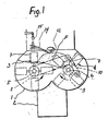
- the mixing machine diagrammatically shown in the figures comprises a mixing chamber 1, that is mounted on a basis 2.
- mixing chamber 1 two parallel vane aggregates 3, 4 are provided.
- Each vane aggregate in a known manner comprises a horizontal shaft 5 and 6, respectively, that is rotatably mounted on bearings (not shown) in the end walls of said mixing chamber.
- Each shaft 5, 6 carried a number of vanes 7.
- both shafts 5,6 project on one end of the mixing chamber 1 and are at that end connected to driving wheels 8, 9, respectively.
- Said drive wheels are driven by a chain 10 which is, in turn, driven by a motor 11.
- the vane aggregates 3 and 4 can, thus, by the aid of motor 11 be driven in opposite directions, as indicated by the arrows in Figure 1.
- Said vane aggregates rotate with a velocity resulting in a floating mixing zone F in the area above and between the rotating shafts 5, 6, as shown in Figure 1.
- a throwing roller 12 is rotatably mounted in both end walls of said mixing chamber. It is rotatably mounted in said end walls in a manner not shown and is connected with a suitable drive motor 13.
- Said throwing roller 12 can be shaped in many different ways, but the roller diagrammatically shown is shaped like a shaft having four radially projecting impellers extending along the entire length of said shaft inside said mixing chamber 1. By the aid of motor 13 said throwing roller 12 can rotate as indicated by the arrow.
- Said throwing roller 12 is provided so as to achieve contact with the particles during mixing operations in zone F. Due to the rotation of throwing roller it will throw a particle fog 14 upwards. Into said particle fog the desired addition agent is injected through the indicated nozzles 15.
- Said throwing roller 12 can in a manner not shown be mounted in the end walls of the mixing chamber so as to be adjustable upwards and down as desired. This is not shown, since this is a structural detail easily accomplished by those skilled in the art.
- the suitable peripheral velocity of vanes 7 in a typical mixing machine of the shown kind will be in the range of 1,2-1,7 m/sec., whereas said throwing roller rotates with a rpm of approximately 1500 rpm/min., dependent on the roller diameter.
- the particle fog formed will be a fog or a curtain where the injected liquid particles will penetrate and be covered, so that adhesion on machine members is avoided.
Landscapes
- Chemical & Material Sciences (AREA)
- Chemical Kinetics & Catalysis (AREA)
- Engineering & Computer Science (AREA)
- Mechanical Engineering (AREA)
- Dispersion Chemistry (AREA)
- Mixers Of The Rotary Stirring Type (AREA)
- Adhesives Or Adhesive Processes (AREA)
- Preparation Of Clay, And Manufacture Of Mixtures Containing Clay Or Cement (AREA)
- Nozzles (AREA)
- Electrical Discharge Machining, Electrochemical Machining, And Combined Machining (AREA)
- Confectionery (AREA)
- Mixers With Rotating Receptacles And Mixers With Vibration Mechanisms (AREA)
- Road Paving Machines (AREA)
- Processing And Handling Of Plastics And Other Materials For Molding In General (AREA)
- Accessories For Mixers (AREA)
Priority Applications (1)
| Application Number | Priority Date | Filing Date | Title |
|---|---|---|---|
| AT86850238T ATE48545T1 (de) | 1985-07-03 | 1986-06-30 | Anordnung in einer mischmaschine. |
Applications Claiming Priority (2)
| Application Number | Priority Date | Filing Date | Title |
|---|---|---|---|
| NO852667 | 1985-07-03 | ||
| NO852667A NO156479C (no) | 1985-07-03 | 1985-07-03 | Anordning ved blandemaskin. |
Publications (3)
| Publication Number | Publication Date |
|---|---|
| EP0219471A2 true EP0219471A2 (de) | 1987-04-22 |
| EP0219471A3 EP0219471A3 (en) | 1987-07-29 |
| EP0219471B1 EP0219471B1 (de) | 1989-12-13 |
Family
ID=19888370
Family Applications (1)
| Application Number | Title | Priority Date | Filing Date |
|---|---|---|---|
| EP86850238A Expired EP0219471B1 (de) | 1985-07-03 | 1986-06-30 | Anordnung in einer Mischmaschine |
Country Status (13)
| Country | Link |
|---|---|
| EP (1) | EP0219471B1 (de) |
| JP (1) | JPS6265726A (de) |
| KR (1) | KR900005497B1 (de) |
| AR (1) | AR240771A1 (de) |
| AT (1) | ATE48545T1 (de) |
| AU (1) | AU582863B2 (de) |
| CA (1) | CA1284635C (de) |
| DE (1) | DE3667409D1 (de) |
| DK (1) | DK167740B1 (de) |
| ES (1) | ES2000449A6 (de) |
| FI (1) | FI85657C (de) |
| IN (1) | IN165459B (de) |
| NO (1) | NO156479C (de) |
Cited By (8)
| Publication number | Priority date | Publication date | Assignee | Title |
|---|---|---|---|---|
| US4911558A (en) * | 1987-06-30 | 1990-03-27 | Lothar Teske | Screw conveyor |
| US6228172B1 (en) * | 1998-10-29 | 2001-05-08 | The Boc Group Plc | Tumble coating |
| WO2001085322A1 (de) * | 2000-05-05 | 2001-11-15 | Ammann Aufbereitung Ag | Zweiwellen-zwangsmischer, verwendung des zweiwellen-zwangsmischers und verfahren zum betrieb eines zweiwellen-zwangsmischers |
| EP1623754A1 (de) * | 2004-08-06 | 2006-02-08 | LOGIC-Logistic Consult Ingenieurgesellschaft mbH | Verfahren und Vorrichtung zur Aufbereitung von Erdstoffen |
| US7147363B1 (en) | 1999-04-08 | 2006-12-12 | Buhler Ag | Device for thermal treatment of flour for hygenic purposes |
| KR100684633B1 (ko) * | 2001-05-04 | 2007-02-20 | 패럴코오포레이션 | 내부 배치 믹서에 개선된 분산성 믹싱 및 분배성 믹싱을제공하기 위한 동기 구동용 4 날개 비-맞물림 로터 |
| KR100694751B1 (ko) * | 2002-11-04 | 2007-03-14 | 암만 아우프베라이퉁 아게 | 양축 강제 혼합기, 양축 강제 혼합기의 사용, 및 양축강제 혼합기의 작동 방법 |
| WO2013140120A1 (en) * | 2012-03-22 | 2013-09-26 | Cipla Limited | Glycerol solvate forms of (r) - 2 - [ [ [3 -methyl -4 (2,2, 2 - trifluoroethoxy) pyridin- 2 - yl] methyl] sulphinyl] - 1h - ben zimidazole |
Families Citing this family (3)
| Publication number | Priority date | Publication date | Assignee | Title |
|---|---|---|---|---|
| ES2151406B1 (es) * | 1998-08-26 | 2001-07-01 | Sotkkum Petrus J M Van | Sistema protector para agujas hipodermicas. |
| KR101582076B1 (ko) | 2015-09-23 | 2016-01-11 | 서동석 | 투-웨이 고속분배 라인을 갖는 유제품용 배합장치 |
| NO343007B1 (en) | 2017-01-27 | 2018-09-24 | Norges Miljoe Og Biovitenskapelige Univ Nmbu | Mixer/Vacuum Coater |
Family Cites Families (6)
| Publication number | Priority date | Publication date | Assignee | Title |
|---|---|---|---|---|
| US2861786A (en) * | 1952-11-28 | 1958-11-25 | Baldwin Lima Hamilton Corp | Pug mill mixer having improved aggregate circulating means |
| DE1097411B (de) * | 1959-12-09 | 1961-01-19 | Wibau Gmbh | Verfahren und Vorrichtung zur Herstellung von Mischungen aus koernigen und/oder feinen Festteilchen mit thermoplastischen Bindemitteln |
| US3800474A (en) * | 1972-06-26 | 1974-04-02 | B Fuerst | Liner plate junction seal |
| US4193700A (en) * | 1979-01-02 | 1980-03-18 | Peter Fahrni | Continuous-flow mixer for the gluing of loose chips of wood, fibers, or other particles |
| JPS55142534A (en) * | 1979-04-24 | 1980-11-07 | Kitagawa Tekkosho:Kk | Horizontal multishaft type mixer |
| US4430003A (en) * | 1980-11-18 | 1984-02-07 | Hawker Siddeley Canada, Inc. | Apparatus for spraying liquids such as resins and waxes on surfaces of particles |
-
1985
- 1985-07-03 NO NO852667A patent/NO156479C/no unknown
-
1986
- 1986-06-19 AU AU58998/86A patent/AU582863B2/en not_active Ceased
- 1986-06-25 IN IN483/CAL/86A patent/IN165459B/en unknown
- 1986-06-30 EP EP86850238A patent/EP0219471B1/de not_active Expired
- 1986-06-30 AT AT86850238T patent/ATE48545T1/de not_active IP Right Cessation
- 1986-06-30 DE DE8686850238T patent/DE3667409D1/de not_active Expired - Lifetime
- 1986-07-02 CA CA000512932A patent/CA1284635C/en not_active Expired - Lifetime
- 1986-07-02 FI FI862823A patent/FI85657C/fi not_active IP Right Cessation
- 1986-07-02 DK DK315086A patent/DK167740B1/da not_active IP Right Cessation
- 1986-07-02 JP JP61155911A patent/JPS6265726A/ja active Pending
- 1986-07-03 KR KR1019860005392A patent/KR900005497B1/ko not_active Expired
- 1986-07-03 AR AR304427A patent/AR240771A1/es active
- 1986-07-03 ES ES868600097A patent/ES2000449A6/es not_active Expired
Cited By (9)
| Publication number | Priority date | Publication date | Assignee | Title |
|---|---|---|---|---|
| US4911558A (en) * | 1987-06-30 | 1990-03-27 | Lothar Teske | Screw conveyor |
| US6228172B1 (en) * | 1998-10-29 | 2001-05-08 | The Boc Group Plc | Tumble coating |
| US7147363B1 (en) | 1999-04-08 | 2006-12-12 | Buhler Ag | Device for thermal treatment of flour for hygenic purposes |
| US7150892B2 (en) | 1999-04-08 | 2006-12-19 | Buhler Ag | Method of thermally treating flour for hygienic purposes |
| WO2001085322A1 (de) * | 2000-05-05 | 2001-11-15 | Ammann Aufbereitung Ag | Zweiwellen-zwangsmischer, verwendung des zweiwellen-zwangsmischers und verfahren zum betrieb eines zweiwellen-zwangsmischers |
| KR100684633B1 (ko) * | 2001-05-04 | 2007-02-20 | 패럴코오포레이션 | 내부 배치 믹서에 개선된 분산성 믹싱 및 분배성 믹싱을제공하기 위한 동기 구동용 4 날개 비-맞물림 로터 |
| KR100694751B1 (ko) * | 2002-11-04 | 2007-03-14 | 암만 아우프베라이퉁 아게 | 양축 강제 혼합기, 양축 강제 혼합기의 사용, 및 양축강제 혼합기의 작동 방법 |
| EP1623754A1 (de) * | 2004-08-06 | 2006-02-08 | LOGIC-Logistic Consult Ingenieurgesellschaft mbH | Verfahren und Vorrichtung zur Aufbereitung von Erdstoffen |
| WO2013140120A1 (en) * | 2012-03-22 | 2013-09-26 | Cipla Limited | Glycerol solvate forms of (r) - 2 - [ [ [3 -methyl -4 (2,2, 2 - trifluoroethoxy) pyridin- 2 - yl] methyl] sulphinyl] - 1h - ben zimidazole |
Also Published As
| Publication number | Publication date |
|---|---|
| FI862823L (fi) | 1987-01-04 |
| AU5899886A (en) | 1987-01-08 |
| JPS6265726A (ja) | 1987-03-25 |
| EP0219471A3 (en) | 1987-07-29 |
| DK315086A (da) | 1987-01-04 |
| NO156479B (no) | 1987-06-22 |
| ES2000449A6 (es) | 1988-03-01 |
| DK167740B1 (da) | 1993-12-13 |
| NO156479C (no) | 1987-09-30 |
| AU582863B2 (en) | 1989-04-13 |
| AR240771A1 (es) | 1991-02-28 |
| KR870000955A (ko) | 1987-03-10 |
| DE3667409D1 (de) | 1990-01-18 |
| FI85657C (fi) | 1992-05-25 |
| AR240771A2 (es) | 1991-02-28 |
| CA1284635C (en) | 1991-06-04 |
| ATE48545T1 (de) | 1989-12-15 |
| EP0219471B1 (de) | 1989-12-13 |
| FI85657B (fi) | 1992-02-14 |
| IN165459B (de) | 1989-10-21 |
| NO852667L (no) | 1987-01-05 |
| DK315086D0 (da) | 1986-07-02 |
| FI862823A0 (fi) | 1986-07-02 |
| KR900005497B1 (ko) | 1990-07-30 |
Similar Documents
| Publication | Publication Date | Title |
|---|---|---|
| US4380398A (en) | Dispersion mixer | |
| EP0219471A2 (de) | Anordnung in einer Mischmaschine | |
| US4188130A (en) | Device for continuously mixing wood chips with binder | |
| US3674241A (en) | Mixing machine | |
| US4848919A (en) | Pinned mill for mixers | |
| JPH0710337B2 (ja) | 撹拌装置 | |
| CN1097649A (zh) | 处理固、液和/或气态物质的装置和使物质活化的方法 | |
| US3414239A (en) | Auxiliary mixing tool for mixing device having a main mixing tool | |
| US4199108A (en) | Apparatus for building up and repairing a refractory lining | |
| SU1664384A1 (ru) | Смеситель | |
| US3266781A (en) | Mixing machine | |
| US3937446A (en) | Apparatus for mixing of building materials | |
| US2326823A (en) | Pipe lining apparatus | |
| US864386A (en) | Machine for mixing materials for concrete. | |
| SU1099990A1 (ru) | Кавитационный реактор дл обработки потока материалов | |
| CN113547634A (zh) | 一种工程物料低尘混拌装置 | |
| JP2004249197A (ja) | 回転投射式の吹付け工法 | |
| SU1646600A1 (ru) | Устройство дл измельчени материалов | |
| RU2005540C1 (ru) | Центробежная дробилка | |
| SU1075013A2 (ru) | Дробильно-сортировочна установка | |
| SU1011246A1 (ru) | Центробежна мельница | |
| SU1694210A1 (ru) | Центробежно-ударна дробилка | |
| JP2775569B2 (ja) | 分散装置 | |
| SU1172732A1 (ru) | Активатор | |
| CA2231693A1 (en) | Double rotating mixing system |
Legal Events
| Date | Code | Title | Description |
|---|---|---|---|
| PUAI | Public reference made under article 153(3) epc to a published international application that has entered the european phase |
Free format text: ORIGINAL CODE: 0009012 |
|
| AK | Designated contracting states |
Kind code of ref document: A2 Designated state(s): AT BE CH DE FR GB IT LI LU NL SE |
|
| PUAL | Search report despatched |
Free format text: ORIGINAL CODE: 0009013 |
|
| AK | Designated contracting states |
Kind code of ref document: A3 Designated state(s): AT BE CH DE FR GB IT LI LU NL SE |
|
| 17P | Request for examination filed |
Effective date: 19870905 |
|
| 17Q | First examination report despatched |
Effective date: 19880829 |
|
| GRAA | (expected) grant |
Free format text: ORIGINAL CODE: 0009210 |
|
| AK | Designated contracting states |
Kind code of ref document: B1 Designated state(s): AT BE CH DE FR GB IT LI LU NL SE |
|
| REF | Corresponds to: |
Ref document number: 48545 Country of ref document: AT Date of ref document: 19891215 Kind code of ref document: T |
|
| REF | Corresponds to: |
Ref document number: 3667409 Country of ref document: DE Date of ref document: 19900118 |
|
| ITF | It: translation for a ep patent filed | ||
| ET | Fr: translation filed | ||
| PGFP | Annual fee paid to national office [announced via postgrant information from national office to epo] |
Ref country code: LU Payment date: 19900606 Year of fee payment: 5 |
|
| PG25 | Lapsed in a contracting state [announced via postgrant information from national office to epo] |
Ref country code: LU Free format text: LAPSE BECAUSE OF NON-PAYMENT OF DUE FEES Effective date: 19900630 |
|
| PLBE | No opposition filed within time limit |
Free format text: ORIGINAL CODE: 0009261 |
|
| STAA | Information on the status of an ep patent application or granted ep patent |
Free format text: STATUS: NO OPPOSITION FILED WITHIN TIME LIMIT |
|
| 26N | No opposition filed | ||
| ITTA | It: last paid annual fee | ||
| EAL | Se: european patent in force in sweden |
Ref document number: 86850238.6 |
|
| PGFP | Annual fee paid to national office [announced via postgrant information from national office to epo] |
Ref country code: GB Payment date: 19980605 Year of fee payment: 13 Ref country code: AT Payment date: 19980605 Year of fee payment: 13 |
|
| PGFP | Annual fee paid to national office [announced via postgrant information from national office to epo] |
Ref country code: SE Payment date: 19980611 Year of fee payment: 13 |
|
| PGFP | Annual fee paid to national office [announced via postgrant information from national office to epo] |
Ref country code: FR Payment date: 19980617 Year of fee payment: 13 |
|
| PGFP | Annual fee paid to national office [announced via postgrant information from national office to epo] |
Ref country code: CH Payment date: 19980618 Year of fee payment: 13 |
|
| PGFP | Annual fee paid to national office [announced via postgrant information from national office to epo] |
Ref country code: DE Payment date: 19980622 Year of fee payment: 13 |
|
| PGFP | Annual fee paid to national office [announced via postgrant information from national office to epo] |
Ref country code: BE Payment date: 19980625 Year of fee payment: 13 |
|
| PGFP | Annual fee paid to national office [announced via postgrant information from national office to epo] |
Ref country code: NL Payment date: 19980630 Year of fee payment: 13 |
|
| PG25 | Lapsed in a contracting state [announced via postgrant information from national office to epo] |
Ref country code: DE Free format text: LAPSE BECAUSE OF THE APPLICANT RENOUNCES Effective date: 19981118 |
|
| PG25 | Lapsed in a contracting state [announced via postgrant information from national office to epo] |
Ref country code: SE Free format text: THE PATENT HAS BEEN ANNULLED BY A DECISION OF A NATIONAL AUTHORITY Effective date: 19990629 |
|
| PG25 | Lapsed in a contracting state [announced via postgrant information from national office to epo] |
Ref country code: LI Free format text: LAPSE BECAUSE OF NON-PAYMENT OF DUE FEES Effective date: 19990630 Ref country code: GB Free format text: LAPSE BECAUSE OF NON-PAYMENT OF DUE FEES Effective date: 19990630 Ref country code: FR Free format text: THE PATENT HAS BEEN ANNULLED BY A DECISION OF A NATIONAL AUTHORITY Effective date: 19990630 Ref country code: CH Free format text: LAPSE BECAUSE OF NON-PAYMENT OF DUE FEES Effective date: 19990630 Ref country code: BE Free format text: LAPSE BECAUSE OF NON-PAYMENT OF DUE FEES Effective date: 19990630 Ref country code: AT Free format text: LAPSE BECAUSE OF NON-PAYMENT OF DUE FEES Effective date: 19990630 |
|
| BERE | Be: lapsed |
Owner name: FORBERG HALVOR Effective date: 19990630 |
|
| PG25 | Lapsed in a contracting state [announced via postgrant information from national office to epo] |
Ref country code: NL Free format text: LAPSE BECAUSE OF NON-PAYMENT OF DUE FEES Effective date: 20000101 |
|
| REG | Reference to a national code |
Ref country code: CH Ref legal event code: PL |
|
| GBPC | Gb: european patent ceased through non-payment of renewal fee |
Effective date: 19990630 |
|
| NLV4 | Nl: lapsed or anulled due to non-payment of the annual fee |
Effective date: 20000101 |
|
| EUG | Se: european patent has lapsed |
Ref document number: 86850238.6 |
|
| REG | Reference to a national code |
Ref country code: FR Ref legal event code: ST |
|
| PG25 | Lapsed in a contracting state [announced via postgrant information from national office to epo] |
Ref country code: IT Free format text: LAPSE BECAUSE OF NON-PAYMENT OF DUE FEES;WARNING: LAPSES OF ITALIAN PATENTS WITH EFFECTIVE DATE BEFORE 2007 MAY HAVE OCCURRED AT ANY TIME BEFORE 2007. THE CORRECT EFFECTIVE DATE MAY BE DIFFERENT FROM THE ONE RECORDED. Effective date: 20050630 |