EP0219621A2 - Erdungsverbindung - Google Patents
Erdungsverbindung Download PDFInfo
- Publication number
- EP0219621A2 EP0219621A2 EP86110289A EP86110289A EP0219621A2 EP 0219621 A2 EP0219621 A2 EP 0219621A2 EP 86110289 A EP86110289 A EP 86110289A EP 86110289 A EP86110289 A EP 86110289A EP 0219621 A2 EP0219621 A2 EP 0219621A2
- Authority
- EP
- European Patent Office
- Prior art keywords
- fitment
- pipe
- inlet
- supply pipe
- water supply
- Prior art date
- Legal status (The legal status is an assumption and is not a legal conclusion. Google has not performed a legal analysis and makes no representation as to the accuracy of the status listed.)
- Ceased
Links
Images

Classifications
-
- F—MECHANICAL ENGINEERING; LIGHTING; HEATING; WEAPONS; BLASTING
- F24—HEATING; RANGES; VENTILATING
- F24H—FLUID HEATERS, e.g. WATER OR AIR HEATERS, HAVING HEAT-GENERATING MEANS, e.g. HEAT PUMPS, IN GENERAL
- F24H9/00—Details
- F24H9/20—Arrangement or mounting of control or safety devices
- F24H9/2007—Arrangement or mounting of control or safety devices for water heaters
- F24H9/2014—Arrangement or mounting of control or safety devices for water heaters using electrical energy supply
- F24H9/2028—Continuous-flow heaters
Definitions
- the present invention relates to a method of earth bonding an electrical fitment to which a water supply is connected.
- Our method requires that a conductive device, which is connected to a metal part of the fitment, be located at the water inlet fitment such that it makes electrical contact with an electrically conductive water supply pipe to provide the required earth continuity.
- the advantage of our method is that it ensures earth continuity is provided since the earth bond is made on connection of the water supply to the fitment and therefore cannot be forgotten, furthermore the wiring is enclosed within the fitment and hidden from sight.
- the present invention provides a method of providing an electric fitment with an earth bond, said fitment having a non-condue- tive body portion containing metallic elements associated with electrically operative parts of the fitment and provided with a water supply thereto comprises providing a conductive device positioned at the fitment water supply inlet to provide an electrical connection to an electrically conductive supply pipe and having a portion connected to a said metallic element within the fitment.
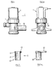
- a solenoid valve generally indicated at 1 comprises a body 2 having a water inlet 3 and a water outlet 4.
- Water inlet 3 is tubular and is formed with a screwthread 6 around its outer periphery to receive a corresponding threaded nut of a cold water supply pipe fitment.
- a section 5 projects forwardly of inlet 3 and has a diameter smaller than the diameter of the remainder of the inlet measnred from the bottom of the screw thread.
- a flat recess 7 is formed in the outer surface of the inlet and has its axis parallel to the axis of the inlet, the base of the recess is at the same level as the outer diameter of the projecting portion 5.
- An earthing ring illustrated in Figs. 2 and 2a comprises a split ring generally indicated at 20 having a gap 21 between the two ends thereof.
- a “tag” 22 extends outwardly of the "inner” edge 24 of the ring to which is soldered an electrical lead 23, the opposite and of which (not shown) conveniently includes means For attachment to the metal parts of the fitment.
- the inside diameter of edge 24 of ring 20 is smaller than the outside diameter of projecting portion 5 of valve inlet 3, the"outer"face portion 25 of the ring 20 having a bevelled edge 26.
- a copper water supply pipe 10 is a sliding fit in water inlet 3 and is retained in position by screw threaded nut 8 and copper olive 9.
- ring 20 is clipped in position on portion 5 at the end of inlet 3 of solenoid valve 1 with edge 24 abutting the shoulder of projecting portion 5 of inlet 3, the tag 22 lying in the recess 7.
- the water supply pipe 10, nut 8 and olive 9 are then presented to the water inlet 3.
- the nut 8 is then tightened onto screw-threaded portion 6, compressing the olive 9 onto pipe 10 to provide a water tight seal, and also forcing the ring 20 into permanent contact with both nut 8 and olive 9. Because the other end of the cable 23 is already attached to a metal part of the heater during manufacture, a satisfactory earth bond is obtained during installation of the heater.
- Figs. 3 and 4 illustrate an alternative form of earth bonding where the solenoid has a tubular inlet portion 30 onto which the water supply pipe is clamped. using a standard compression joint.
- the bonding is achieved by use of a copper sleeve generally indicated at 40 in Fig. 4 which has a body portion 41 and an end portion 42 of slightly wider diameter, an electrical cable 43 is soldered onto portion 42 and conveniently also includes a tag (not shown) for connection to a metal portion of the fitment.
- the diameter of portion 41 is such that sleeve 40 is a force fit over the inlet 30 of solenoid 1, portion 42 providing a convenient lead-in.
- the instantaneous water heater will normally be provided with solenoid 1 already fitted with sleeve 40 and the connection between the sleeve and metal part of the heater fitment made during manufacture. On installation of the heater clamping of the mains water supply pipe, again using a compression joint, to the water inlet provides the required bonding.
Landscapes
- Engineering & Computer Science (AREA)
- Physics & Mathematics (AREA)
- Thermal Sciences (AREA)
- Chemical & Material Sciences (AREA)
- Combustion & Propulsion (AREA)
- Mechanical Engineering (AREA)
- General Engineering & Computer Science (AREA)
- Resistance Heating (AREA)
- Magnetically Actuated Valves (AREA)
Applications Claiming Priority (2)
| Application Number | Priority Date | Filing Date | Title |
|---|---|---|---|
| GB8519396 | 1985-08-01 | ||
| GB858519396A GB8519396D0 (en) | 1985-08-01 | 1985-08-01 | Earth bonding |
Publications (2)
| Publication Number | Publication Date |
|---|---|
| EP0219621A2 true EP0219621A2 (de) | 1987-04-29 |
| EP0219621A3 EP0219621A3 (de) | 1988-09-21 |
Family
ID=10583184
Family Applications (1)
| Application Number | Title | Priority Date | Filing Date |
|---|---|---|---|
| EP86110289A Ceased EP0219621A3 (de) | 1985-08-01 | 1986-07-25 | Erdungsverbindung |
Country Status (2)
| Country | Link |
|---|---|
| EP (1) | EP0219621A3 (de) |
| GB (1) | GB8519396D0 (de) |
Cited By (2)
| Publication number | Priority date | Publication date | Assignee | Title |
|---|---|---|---|---|
| JP2018003256A (ja) * | 2016-06-27 | 2018-01-11 | アイシン精機株式会社 | 局部洗浄装置 |
| WO2021014373A1 (fr) * | 2019-07-23 | 2021-01-28 | Suez Groupe | Ensemble de comptage d'un fluide |
Family Cites Families (3)
| Publication number | Priority date | Publication date | Assignee | Title |
|---|---|---|---|---|
| GB496155A (en) * | 1937-09-07 | 1938-11-25 | Reuben Dight | Instantaneous electric water heating apparatus |
| US3260790A (en) * | 1964-02-17 | 1966-07-12 | Alsup W Homer | Deformable non-metallic conduit coupling with grounding connections |
| US3537065A (en) * | 1967-01-12 | 1970-10-27 | Jerrold Electronics Corp | Multiferrule cable connector |
-
1985
- 1985-08-01 GB GB858519396A patent/GB8519396D0/en active Pending
-
1986
- 1986-07-25 EP EP86110289A patent/EP0219621A3/de not_active Ceased
Cited By (2)
| Publication number | Priority date | Publication date | Assignee | Title |
|---|---|---|---|---|
| JP2018003256A (ja) * | 2016-06-27 | 2018-01-11 | アイシン精機株式会社 | 局部洗浄装置 |
| WO2021014373A1 (fr) * | 2019-07-23 | 2021-01-28 | Suez Groupe | Ensemble de comptage d'un fluide |
Also Published As
| Publication number | Publication date |
|---|---|
| GB8519396D0 (en) | 1985-09-04 |
| EP0219621A3 (de) | 1988-09-21 |
Similar Documents
| Publication | Publication Date | Title |
|---|---|---|
| US3040284A (en) | Termination fitting for mineral-insulated metal-sheath cable | |
| CA1170735A (en) | Electrical connector | |
| JPH077837A (ja) | ケーブルグランド | |
| US20050218733A1 (en) | Method and means of sealing an electrical conductor through the housing of a fluid filled motor | |
| US6835088B2 (en) | EMT rain-tight compression fittings | |
| CA2290483A1 (en) | Fuseholder and connector | |
| CA2068692A1 (en) | Electrical wire connector | |
| CA1208327A (en) | Sealed cable connector | |
| CA2417954A1 (en) | Device for connecting components made of fusible plastic | |
| MXPA02002727A (es) | Dispositivo de retencion axial de un elemento cilindrico y mas particularmente un cable. | |
| US20220077628A1 (en) | Plug screw connection system | |
| US3663919A (en) | Grounding spring for electrical fixtures | |
| US3346274A (en) | Insulated union coupling | |
| EP0219621A2 (de) | Erdungsverbindung | |
| US6165004A (en) | Power line connector/tap splice apparatus | |
| EP0094122B1 (de) | Klemme | |
| US5912434A (en) | Kenny Clamp | |
| US6857902B2 (en) | Proximity switch and a cable terminal part unit and a process for its manufacture | |
| SE507195C2 (sv) | Skarvhylsa försedd med momentskruvar | |
| US7008244B2 (en) | Earthing pipes | |
| FR2637420A3 (fr) | Partie de connecteur electrique, et connecteur le comportant | |
| GB2278171A (en) | Supply cable connector | |
| GB2179528A (en) | Earth bonding | |
| EP0114455A1 (de) | Leitungskupplung | |
| US3963915A (en) | Watertight light assembly |
Legal Events
| Date | Code | Title | Description |
|---|---|---|---|
| PUAI | Public reference made under article 153(3) epc to a published international application that has entered the european phase |
Free format text: ORIGINAL CODE: 0009012 |
|
| AK | Designated contracting states |
Kind code of ref document: A2 Designated state(s): BE DE FR IT NL SE |
|
| RAP1 | Party data changed (applicant data changed or rights of an application transferred) |
Owner name: TRITON PLC |
|
| PUAL | Search report despatched |
Free format text: ORIGINAL CODE: 0009013 |
|
| AK | Designated contracting states |
Kind code of ref document: A3 Designated state(s): BE DE FR IT NL SE |
|
| 17P | Request for examination filed |
Effective date: 19881206 |
|
| 17Q | First examination report despatched |
Effective date: 19901108 |
|
| STAA | Information on the status of an ep patent application or granted ep patent |
Free format text: STATUS: THE APPLICATION HAS BEEN REFUSED |
|
| 18R | Application refused |
Effective date: 19920329 |
|
| RIN1 | Information on inventor provided before grant (corrected) |
Inventor name: DALTON, MARTIN WALTER |