EP0219632B1 - Boîte avec surface pour déposer et espace de rangement - Google Patents
Boîte avec surface pour déposer et espace de rangement Download PDFInfo
- Publication number
- EP0219632B1 EP0219632B1 EP86111008A EP86111008A EP0219632B1 EP 0219632 B1 EP0219632 B1 EP 0219632B1 EP 86111008 A EP86111008 A EP 86111008A EP 86111008 A EP86111008 A EP 86111008A EP 0219632 B1 EP0219632 B1 EP 0219632B1
- Authority
- EP
- European Patent Office
- Prior art keywords
- lid
- box according
- deposit box
- box
- deposit
- Prior art date
- Legal status (The legal status is an assumption and is not a legal conclusion. Google has not performed a legal analysis and makes no representation as to the accuracy of the status listed.)
- Expired - Lifetime
Links
Images


Classifications
-
- B—PERFORMING OPERATIONS; TRANSPORTING
- B60—VEHICLES IN GENERAL
- B60R—VEHICLES, VEHICLE FITTINGS, OR VEHICLE PARTS, NOT OTHERWISE PROVIDED FOR
- B60R7/00—Stowing or holding appliances inside vehicle primarily intended for personal property smaller than suit-cases, e.g. travelling articles, or maps
- B60R7/04—Stowing or holding appliances inside vehicle primarily intended for personal property smaller than suit-cases, e.g. travelling articles, or maps in driver or passenger space, e.g. using racks
Definitions
- the invention relates to a storage box with storage space, in particular for trucks, which can be attached to the tunnel between the driver and front passenger seats.
- the invention has for its object to provide a storage box that allows greater possibilities for storing objects, including those of larger dimensions, and a variety of uses for one or more lid parts with ergonomically favorable adjustment devices.
- the storage box has at least two storage spaces which can optionally be closed by a lid.
- the arrangement of two storage spaces has the advantage that you can accommodate larger quantities, on the other hand, you can conveniently separate different categories of items, such. B. in a storage space desk pads of any kind, in the other drinks or food.
- the storage box is designed in two parts and consists of a basic box and a preferably higher side box, and each box is assigned a storage space, with the basic box being attachable on its own and, if necessary, expandable with the side box.
- This arrangement results in the advantage that the device according to the invention can be varied and also expanded afterwards.
- the basic box for storing smaller consumer goods such. B.
- the side box can be used for storing larger objects such as bottles and the like. So the side box could also be designed as a cool box in one embodiment. According to another training, the storage box can also be designed in one piece. This is a particularly inexpensive version.
- the different versions of the lids shown below can be brought into different positions of use via the different storage spaces of the two boxes.
- the storage spaces can be optionally locked and the lids serve different purposes depending on their respective use, e.g., as can be removed in detail, as a table with border or as a desk.
- some embodiments of the lid have a further storage space. It is emphasized here that there are three embodiments of the lid in a real storage space integrated into the same, which does not lose its sense in the wrong direction by tilting or rotating, as is the case with the known storage. Rather, as a practical addition to the table function of the lid, small items such as. B. cups or cutlery can be accommodated, which are therefore in direct access.
- a particularly advantageous embodiment characterizing the invention can be seen in the fact that the cover can be moved from its first position of use above the storage space of the basic box into a second position of use above the storage space of the side box by means of a combined, translatory-rotary movement.
- the cover with unchanged position of the cover storage space can be brought from the position of use above the storage space of the basic box into the position of use above the storage space of the side box by a slightly pushing hand movement.
- the driver or the front passenger can carry out this change of position with little movement effort, without his attention being distracted from the traffic, as is undoubtedly the case with a lid turning movement with a relatively large swivel radius.
- the contact surfaces on the boxes are designed as inclined surfaces, and the undersides of the cover have corresponding inclines. This enables an elegant transfer of the cover from one position to the other.
- guide strips are provided above the lateral edges of the boxes for secure guidance of the cover. These strips absorb lateral forces, thus preventing unnecessary stress on the handlebars and increasing the lifespan of the storage box.
- the guide rails correspond to the path of the moving lid arched towards the center. In this way, the side forces are absorbed during the entire risk of movement of the lid.
- the cover drive is designed as a parallelogram link mechanism.
- This embodiment is the simplest implementation of a combined rotary-translational movement as a practical device and is achieved with simple, inexpensive means.
- the cover can be moved from a lower position into a longitudinally offset, upper position by means of the parallelogram link mechanism, the upper end position of the link being beyond the vertical.
- the cover in addition to the lower, gravity-related position of use of the cover, an equally safe upper position of use is achieved due to the kinematic use of the over-vertical position of the handlebars.
- the lower articulation points of the handlebars are located on the side box and the upper articulation points on the cover or the lower articulation points on the basic box and the upper articulations in turn on the cover.
- the advantageous arrangement allows the individual or combined set-up of basic and side boxes, as well as retrofitting.
- the storage space of the lid can be closed by means of a loose closure plate lying in it and the plate can be moved vertically into two different positions of use.
- the closure plate fulfills two functions, firstly it closes the lid storage space, which thus represents a real, closed container, and secondly it serves as a support for everyday items.
- the fact that the closure plate is loosely arranged means that the lid storage space is easily accessible at all times, and that it can take up two different positions of use, being movable in height, it can be used for different purposes.
- a lower use position of the closure plate with an edge boundary through the upper part of the walls of the lid storage space and with the upper use position of the cover, which extends over the side box, an upper position Use position of the plate now lying flush with the edges of the cover walls.
- the arrangement means that the lower position of use of the lid offers a table with an edge, which it z. B. allowed to put a cup without it could tip over the edge of the table due to vehicle movements, on the other hand, the lid shows the closure plate in its upper position of use with its edges lying flush, so that here a desk arrangement is given.
- the closure plate has a lever which extends through a recess in the front edge of the cover for lifting the closure plate.
- the locking plate can be brought automatically from the lower into the upper position of use by means of eccentric levers which are firmly connected to the upper hinge pins of the handlebars and which are arranged on the inside of the cover.
- the storage box has only a single pair of levers, one pivot point of rotation being arranged on one of the two boxes and the other on the lid, preferably in the center of gravity of the same, and the lid being defined from one defined position of use to another over an unstable movement phase Use position can be brought.
- This cover drive is cheaper with only one pair of levers and also achieves two defined positions of use, although in the movement phase the cover must be guided by hand in order to avoid a rocking movement.
- the cover can be moved by means of a sliding movement from a first position of use above the storage space of the basic box to a second position of use above the storage space of the side box.
- the cover can be brought to different (heights) by means of light hand pressure over a clear guideway, preferably over an inclined plane.
- sliding surfaces are provided on the underside of the lid and on the side edges of the boxes for the sliding movement, and the lid assumes its end positions (positions of use) on the slopes. This enables the cover to be easily longitudinally displaceable at defined end positions, as detailed below.
- the cover is guided by means of strips, preferably integrally connected to it, in grooves of guide strips, the grooves at the lower end of the guide strips being closed and the strips at the upper end having resilient elements which lie in grooves in the strips and which Reach behind the back wall of the side box.
- a clear lateral guidance is effected, as is also preventing the lid from being raised.
- it is prescribed to achieve the upper position fixing of the cover with the aid of a simple spring element.
- the cover can be moved by means of a rotary movement from a lower position of use extending over the storage space of the basic box into an upper position of use extending over the storage space of the side box.
- the rotary movement being carried out via a on the cover and on the front ren edge part of the side box attached hinge takes place.
- the cover is bowl-shaped and closes the base box convexly in the first position of use and concave the side box in its second position of use pivoted by 180 ° .
- the edge parts of the basic box of the same height are lower by the height of the lid than the front edge part of the side box and this in turn are lower by the clear lid depth than the rear edge part and the lateral edge parts of the lid grip over themselves from the level of the higher one rear side edge parts of the side box tapering to the level of the lower front edge part.
- This arrangement and design of basic box, side box and lid allows the lid to complete different levels in its positions of use and its top surface in the lower position of use is a bowl and in the upper position of use is a table top.
- a snap lock is arranged between the cover and the side box on the one hand and between the cover and the base box on the other. This prevents the cover from making unwanted movements due to vehicle vibrations and shocks.
- the basic box and the side box can be locked together in their two-part design. This feature applies to all types of design and is intended to connect the basic and side boxes uniformly so that they cannot move against each other while driving.
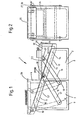
- Fig. 1 and Fig. 2 show a storage box 1, which consists essentially of a basic box 8 with a storage space 2, a side box 9 with a storage space 3 and a lid 4 with a storage space 10.
- the boxes 8, 9 have on their upper lateral edges 13, 13 'of the order compartments 11, on which the undersides 12 of the cover 4, which are formed in the same slant, come to rest. 14 and 14 'are guide strips above the lateral edges 13, 13' of the boxes 8, 9, in which the cover 4 is guided against lateral deflection.
- the cover 4 can be moved by means of a parallelogram link mechanism 15 from a lower to an upper position of use, in the upper position of use the links 16 and 17 have a position which extends beyond the vertical, thereby achieving a defined end position for the cover.
- the handlebars 16, 17 have their lower articulation points 18, 19 at the base of the side box 9 and their upper articulation points 20, 21 on the lid 4.
- the storage space 10 of the lid 4 is closed with a closure plate 22, which in the lower position of use of the lid the storage space is inserted and bordered by the edge boundary 23 of the walls 24, while in the upper position of use it is flush with the edge boundary.
- the front of the boundary 23 has a recess 25 which is penetrated by a lever 26 which is integrally connected to the closure plate 22.
- the hinge pins 27, 28 are arranged in the upper hinge points 20, 21. These protrude into the storage space 10 of the lid 4 and are firmly connected to eccentric levers 29, 30, as are also firmly connected to the links 16, 17 and are rotatably mounted in the lid walls 24.
- Fig. 3 shows a second embodiment of the invention.
- only one pair of levers 31 with the pivot points 32 and 32 ' is arranged between the side box 9 and the cover 4'.
- This version also has two defined end positions, but has an unstable movement phase.
- FIGS 4 and 5 show a third embodiment of the invention.
- the cover 4 "has inclined sliding surfaces 33, by means of which the cover on the likewise inclined sliding surfaces 34 of the boxes 8 and 9 can be pushed from a lower position of use above the basic box to an upper position of use above the side box.
- the cover 4" is by means of strips 35 guided in grooves 36 of the guide strips 37, which are preferably integrally connected to the boxes 8, 9.
- the strips 35 have at their upper ends small grooves 39, in which springs 38 lie, which engage behind the rear wall 40 of the side box 9 in a locking manner.
- the groove 36 located in the guide strip is open at the top for pushing in the cover 4 "and closed at the front at the bottom for fixing the cover in its lower position of use, the strip 35 of the cover 4" coming into contact with the end wall.
- a handle opening 42 In the front wall 41 of the cover there is a handle opening 42 for pushing and pulling the same.
- the edges 43 are flush with the closure plate 22.
- FIG. 6 shows a last exemplary embodiment of the invention with a lid 4 "'which is rotatably mounted by means of a hinge 53 which is fastened on one end to the inner edge part 45 of the lid and at the other end on the front edge part 44 of the side case 9.
- the lid 4 "'ver closes the basic box 8 in a first position of use and the side box 9 in a second position of use, the bottom of the bowl-shaped cover resting on the higher, rear edge part 46, the side edge parts 48 of the cover 4 ′′ overlap the side edge parts 49 of the side box 9.
- the cover protrudes with a projection 50 beyond the rear rear wall 48 of the side box 9.
- the edge part 51 of the cover has a handle opening 52. Snap closures 54 and 55 fix the cover 4 ′′ in its end positions.
Landscapes
- Engineering & Computer Science (AREA)
- Mechanical Engineering (AREA)
- Closures For Containers (AREA)
- Combinations Of Kitchen Furniture (AREA)
- Vehicle Step Arrangements And Article Storage (AREA)
Claims (33)
Applications Claiming Priority (2)
| Application Number | Priority Date | Filing Date | Title |
|---|---|---|---|
| DE19853534098 DE3534098A1 (de) | 1985-09-25 | 1985-09-25 | Ablagekasten mit stauraum |
| DE3534098 | 1985-09-25 |
Publications (2)
| Publication Number | Publication Date |
|---|---|
| EP0219632A1 EP0219632A1 (fr) | 1987-04-29 |
| EP0219632B1 true EP0219632B1 (fr) | 1990-03-14 |
Family
ID=6281846
Family Applications (1)
| Application Number | Title | Priority Date | Filing Date |
|---|---|---|---|
| EP86111008A Expired - Lifetime EP0219632B1 (fr) | 1985-09-25 | 1986-08-09 | Boîte avec surface pour déposer et espace de rangement |
Country Status (2)
| Country | Link |
|---|---|
| EP (1) | EP0219632B1 (fr) |
| DE (2) | DE3534098A1 (fr) |
Cited By (1)
| Publication number | Priority date | Publication date | Assignee | Title |
|---|---|---|---|---|
| US6874667B2 (en) | 1999-11-30 | 2005-04-05 | Johnson Controls Technology Company | Vehicle cargo management system |
Families Citing this family (11)
| Publication number | Priority date | Publication date | Assignee | Title |
|---|---|---|---|---|
| DE3711001A1 (de) * | 1987-04-01 | 1988-10-20 | Iveco Magirus | Ablage fuer kraftfahrzeuge, insbesondere im tunnelbereich eines lastkraftwagens zwischen fahrer- und beifahrersitz |
| IT214349Z2 (it) * | 1988-02-12 | 1990-05-03 | Groppo Domenico | Accessorio per autoveicolo composto da un portablocco per appunti e da un portamonete |
| GB2223466A (en) * | 1988-08-23 | 1990-04-11 | Autofax International Limited | Accessory for use in a vehicle |
| GB9108626D0 (en) * | 1991-04-23 | 1991-06-12 | Rover Group | A motor vehicle interior fitting |
| DE4401558A1 (de) * | 1994-01-20 | 1995-07-27 | Bayerische Motoren Werke Ag | Transportbehälter, insbesondere für einen Gepäckraum eines Kraftfahrzeugs |
| US5562331A (en) * | 1994-12-09 | 1996-10-08 | Prince Corporation | Storage compartment with cover |
| DE19542198C2 (de) * | 1995-11-13 | 2000-10-12 | Daimler Chrysler Ag | Armauflage für eine Mittelkonsole eines Kraftfahrzeugs |
| DE102006023038B4 (de) * | 2006-05-17 | 2008-04-17 | Faurecia Autositze Gmbh | Rückenlehne eines Kraftfahrzeug-Fondsitzes |
| ATE471842T1 (de) | 2007-10-31 | 2010-07-15 | Fiat Ricerche | Tunnelkonsole für den passagierraum eines fahrzeugs |
| US8919847B2 (en) | 2012-10-02 | 2014-12-30 | Chrysler Group Llc | Deployable center console |
| DE202016103399U1 (de) | 2016-06-28 | 2016-07-11 | Dr. Schneider Kunststoffwerke Gmbh | Aufbewahrungsbehälter für ein Kraftfahrzeug |
Family Cites Families (10)
| Publication number | Priority date | Publication date | Assignee | Title |
|---|---|---|---|---|
| GB177919A (en) * | 1921-01-28 | 1922-04-13 | Henry James Durrant | Improvements in or relating to boxes composed of cardboard, paper, and the like |
| DE733405C (de) * | 1940-09-17 | 1943-03-26 | Theodor Schneider | Naehkasten |
| FR880384A (fr) * | 1940-12-09 | 1943-03-24 | Système de fermeture semi-automatique pour boites comprenant plusieurs compartiments | |
| DE1977799U (de) * | 1966-08-06 | 1968-01-25 | Sattler Atlan Werk Kg L | Werkzeugkoffer. |
| US3870210A (en) * | 1973-10-05 | 1975-03-11 | Jr Earl M Trammell | Container unit for an automobile |
| US4195734A (en) * | 1978-11-06 | 1980-04-01 | Boner John O | Apparatus for transporting medications or the like |
| DE2924979C2 (de) * | 1979-06-21 | 1982-05-13 | Daimler-Benz Ag, 7000 Stuttgart | Ablage für Kraftfahrzeuge |
| DE2935966A1 (de) * | 1979-09-06 | 1981-04-02 | VEB (B) Zieh-, Preß - und Stanzwerk Zwintschöna, DDR 4101 Zwintschöna | Werkzeugkasten mit seitlich ausklappbaren oberteilen |
| DE3245394C2 (de) * | 1982-12-08 | 1984-09-27 | Daimler-Benz Ag, 7000 Stuttgart | Ablage für Kraftfahrzeuge, insbesondere im Tunnelbereich von Lastkraftwagen zwischen Fahrer- und Beifahrersitz befestigbare Ablage |
| DE3501714A1 (de) * | 1985-01-19 | 1986-07-24 | Iveco Magirus AG, 7900 Ulm | Ablageanordnung fuer kraftfahrzeuge, insbesondere im tunnelbereich von lastkraftwagen |
-
1985
- 1985-09-25 DE DE19853534098 patent/DE3534098A1/de active Granted
-
1986
- 1986-08-09 DE DE8686111008T patent/DE3669465D1/de not_active Expired - Lifetime
- 1986-08-09 EP EP86111008A patent/EP0219632B1/fr not_active Expired - Lifetime
Cited By (1)
| Publication number | Priority date | Publication date | Assignee | Title |
|---|---|---|---|---|
| US6874667B2 (en) | 1999-11-30 | 2005-04-05 | Johnson Controls Technology Company | Vehicle cargo management system |
Also Published As
| Publication number | Publication date |
|---|---|
| EP0219632A1 (fr) | 1987-04-29 |
| DE3534098A1 (de) | 1987-04-02 |
| DE3534098C2 (fr) | 1992-08-27 |
| DE3669465D1 (de) | 1990-04-19 |
Similar Documents
| Publication | Publication Date | Title |
|---|---|---|
| DE69305891T2 (de) | Werkzeugkasten mit Werkzeugpalette | |
| EP0219632B1 (fr) | Boîte avec surface pour déposer et espace de rangement | |
| EP0667258B1 (fr) | Dispositif pour tenir des récipients de boissons | |
| DE19908909C2 (de) | Mittelkonsole zwischen Sitzen eines Kraftfahrzeuges mit einem verschließbaren Ablageraum | |
| DE4327869C1 (de) | Ablagefach mit Schließklappe und an dieser angeordnetem Klapptisch | |
| DE102009030577A1 (de) | Konsole eines Kraftfahrzeugs mit einem Behältnis zur Aufnahme eines Gegenstandes | |
| DE3247796A1 (de) | Aufbewahrungsvorrichtung fuer scheibenfoermige aufzeichnungstraeger | |
| DE10361689B4 (de) | Becherhalter für ein Fahrzeug | |
| DE4415732C2 (de) | Armlehne zwischen zwei nebeneinander angeordneten Sitzen eines Kraftfahrzeugs | |
| DE102015102896A1 (de) | Aufbewahrungsanordnung für ein Kraftfahrzeug | |
| EP0624490B1 (fr) | Cendrier pour véhicules | |
| DE102021134568A1 (de) | Becherhaltervorrichtung vom verdeckten typ, fahrzeugarmstütze, die die haltervorrichtung aufweist, und transportmittel, welches diese aufweist | |
| DE19813290A1 (de) | Abdeckung für Verdeckkästen von Cabriofahrzeugen | |
| DE19624888A1 (de) | Besteckkorb für eine Geschirrspülmaschine | |
| DE2935817A1 (de) | Verkaufsautomat | |
| DE202005003650U1 (de) | Halter für Gebrauchsgegenstände | |
| DE19519507C2 (de) | Transportvorrichtung, wie z. B. für Personen- oder Kombinationskraftwagen, mit einem Behälter für langgestrecktes Ladegut, wie z. B. für Skier | |
| DE202018103641U1 (de) | Handschuhfach mit einer Aufnahme | |
| DE9212168U1 (de) | Ablage- und Haltevorrichtung zur Verwendung in einem Kraftfahrzeug | |
| DE202012008816U1 (de) | Behälter, insbesondere zur Aufnahme von Erste-Hilfe-Materialien | |
| EP1258392B1 (fr) | Porte récipient, en particulier pour l'aménagement intérieur de véhicule | |
| DE20308296U1 (de) | Ablagefach | |
| DE102022213335A1 (de) | Behälterhalter für den Innenraum eines Kraftfahrzeugs | |
| DE1191740B (de) | Deckelverschluss fuer Muellgefaesse, die durch eine Einschuettvorrichtung am Muellwagen staubfrei entleert werden koennen | |
| DE3027024A1 (de) | Behaelter zur aufbewahrung einer kassette mit bandfoermigem aufzeichnungstraeger, insbesondere video-kassette |
Legal Events
| Date | Code | Title | Description |
|---|---|---|---|
| PUAI | Public reference made under article 153(3) epc to a published international application that has entered the european phase |
Free format text: ORIGINAL CODE: 0009012 |
|
| AK | Designated contracting states |
Kind code of ref document: A1 Designated state(s): DE FR GB IT NL SE |
|
| 17P | Request for examination filed |
Effective date: 19870602 |
|
| 17Q | First examination report despatched |
Effective date: 19890717 |
|
| RAP1 | Party data changed (applicant data changed or rights of an application transferred) |
Owner name: MAN NUTZFAHRZEUGE AKTIENGESELLSCHAFT |
|
| ITF | It: translation for a ep patent filed | ||
| GRAA | (expected) grant |
Free format text: ORIGINAL CODE: 0009210 |
|
| AK | Designated contracting states |
Kind code of ref document: B1 Designated state(s): DE FR GB IT NL SE |
|
| REF | Corresponds to: |
Ref document number: 3669465 Country of ref document: DE Date of ref document: 19900419 |
|
| ET | Fr: translation filed | ||
| GBT | Gb: translation of ep patent filed (gb section 77(6)(a)/1977) | ||
| PLBE | No opposition filed within time limit |
Free format text: ORIGINAL CODE: 0009261 |
|
| STAA | Information on the status of an ep patent application or granted ep patent |
Free format text: STATUS: NO OPPOSITION FILED WITHIN TIME LIMIT |
|
| 26N | No opposition filed | ||
| ITTA | It: last paid annual fee | ||
| PGFP | Annual fee paid to national office [announced via postgrant information from national office to epo] |
Ref country code: DE Payment date: 19920818 Year of fee payment: 7 |
|
| PGFP | Annual fee paid to national office [announced via postgrant information from national office to epo] |
Ref country code: NL Payment date: 19930831 Year of fee payment: 8 |
|
| PG25 | Lapsed in a contracting state [announced via postgrant information from national office to epo] |
Ref country code: DE Effective date: 19940503 |
|
| PGFP | Annual fee paid to national office [announced via postgrant information from national office to epo] |
Ref country code: GB Payment date: 19940801 Year of fee payment: 9 |
|
| PGFP | Annual fee paid to national office [announced via postgrant information from national office to epo] |
Ref country code: SE Payment date: 19940831 Year of fee payment: 9 Ref country code: FR Payment date: 19940831 Year of fee payment: 9 |
|
| EAL | Se: european patent in force in sweden |
Ref document number: 86111008.8 |
|
| PG25 | Lapsed in a contracting state [announced via postgrant information from national office to epo] |
Ref country code: NL Effective date: 19950301 |
|
| NLV4 | Nl: lapsed or anulled due to non-payment of the annual fee | ||
| PG25 | Lapsed in a contracting state [announced via postgrant information from national office to epo] |
Ref country code: GB Effective date: 19950809 |
|
| PG25 | Lapsed in a contracting state [announced via postgrant information from national office to epo] |
Ref country code: SE Effective date: 19950810 |
|
| GBPC | Gb: european patent ceased through non-payment of renewal fee |
Effective date: 19950809 |
|
| PG25 | Lapsed in a contracting state [announced via postgrant information from national office to epo] |
Ref country code: FR Effective date: 19960430 |
|
| EUG | Se: european patent has lapsed |
Ref document number: 86111008.8 |
|
| REG | Reference to a national code |
Ref country code: FR Ref legal event code: ST |
|
| PG25 | Lapsed in a contracting state [announced via postgrant information from national office to epo] |
Ref country code: IT Free format text: LAPSE BECAUSE OF NON-PAYMENT OF DUE FEES;WARNING: LAPSES OF ITALIAN PATENTS WITH EFFECTIVE DATE BEFORE 2007 MAY HAVE OCCURRED AT ANY TIME BEFORE 2007. THE CORRECT EFFECTIVE DATE MAY BE DIFFERENT FROM THE ONE RECORDED. Effective date: 20050809 |