EP0219734A2 - Verstaubarer grossflächiger Solargeneratormodul - Google Patents
Verstaubarer grossflächiger Solargeneratormodul Download PDFInfo
- Publication number
- EP0219734A2 EP0219734A2 EP86113550A EP86113550A EP0219734A2 EP 0219734 A2 EP0219734 A2 EP 0219734A2 EP 86113550 A EP86113550 A EP 86113550A EP 86113550 A EP86113550 A EP 86113550A EP 0219734 A2 EP0219734 A2 EP 0219734A2
- Authority
- EP
- European Patent Office
- Prior art keywords
- module
- panels
- large area
- flexible
- knuckles
- Prior art date
- Legal status (The legal status is an assumption and is not a legal conclusion. Google has not performed a legal analysis and makes no representation as to the accuracy of the status listed.)
- Granted
Links
Images


Classifications
-
- H—ELECTRICITY
- H02—GENERATION; CONVERSION OR DISTRIBUTION OF ELECTRIC POWER
- H02S—GENERATION OF ELECTRIC POWER BY CONVERSION OF INFRARED RADIATION, VISIBLE LIGHT OR ULTRAVIOLET LIGHT, e.g. USING PHOTOVOLTAIC [PV] MODULES
- H02S30/00—Structural details of PV modules other than those related to light conversion
- H02S30/20—Collapsible or foldable PV modules
-
- Y—GENERAL TAGGING OF NEW TECHNOLOGICAL DEVELOPMENTS; GENERAL TAGGING OF CROSS-SECTIONAL TECHNOLOGIES SPANNING OVER SEVERAL SECTIONS OF THE IPC; TECHNICAL SUBJECTS COVERED BY FORMER USPC CROSS-REFERENCE ART COLLECTIONS [XRACs] AND DIGESTS
- Y02—TECHNOLOGIES OR APPLICATIONS FOR MITIGATION OR ADAPTATION AGAINST CLIMATE CHANGE
- Y02E—REDUCTION OF GREENHOUSE GAS [GHG] EMISSIONS, RELATED TO ENERGY GENERATION, TRANSMISSION OR DISTRIBUTION
- Y02E10/00—Energy generation through renewable energy sources
- Y02E10/50—Photovoltaic [PV] energy
Definitions
- This invention relates generally to photovoltaic devices and more particularly to relatively large area power generating modules. Most particularly, the invention relates to a large area electrical power generating photovoltaic module formed of a flexible, light-weight material, which module may be readily compacted for storage and deployed for use.
- Photovoltaic devices are attractive sources of power insofar as they are relatively compact, silent, nonpolluting and consume no expendable natural resources in their operation.
- Solar photovoltaic energy sources are particularly attractive in those areas or under those conditions where power-grid supplied electricity is unavailable.
- Solar photovoltaic power is used in military and aerospace applications, in agricultural applications, in developing nations and by persons engaged in recreational pursuits such as camping, boating, mountain climbing and the like.
- Single crystal photovoltaic devices especially silicon photovoltaic devices have been utilized for some time as sources of electrical power.
- the utility of such devices is limited by problems associated with their manufacture. More particularly, single crystal materials (1) are difficult to produce in sizes substantially larger than several inches in diameter, (2) are relatively thick and heavy; and (3) are expensive and time consuming to fabricate. Consequently, single crystal photovoltaic power modules are limited in use by cost, bulk and fragility; accordingly, there is a need for a source of solar photovoltaic power which is rugged, reliable, readily transportable and low in cost.
- amorphous semiconductor films each of which can encompass relatively large areas, and which can be doped to form p-type and n-type materials for the production of p-i-n type devices substantially equivalent to those produced by their crystalline counterparts.
- amorphous includes all materials or alloys which have long range disorder, although they may have short or intermediate range order or even contain, at times, crystalline inclusions.
- the large area semiconductor material thus produced may be used as a single large area photovoltaic cell or may be configured into a variety of smaller area photovoltaic cells as well as modules comprised of arrays of interconnected smaller area devices.
- a large area photovoltaic cell tolerant of defects in or damage to smaller area portions thereof may be produced by interconnecting a plurality of smaller area cells in a mixed series-parallel relationship.
- the assignee of the instant invention has also developed techniques for sequentially depositing layers of semiconductor material upon a very thin, flexible substrate material so as to allow for the manufacture of "ultralight” photovoltaic cells and modules manifesting extemely high power to weight ratios.
- Such techniques are disclosed in U.S. patent application serial No. 696,390 filed January 30, 1985 and entitled “Extremely Lightweight, Flexible Semiconductor Device Arrays and Method of Making Same," the disclosure of which is incorporated herein by reference. Since it is now possible to manufacture lightweight and ultralightweight flexible solar cell power sources, it would be highly advantageous to incorporate such solar cell power sources into modules, which modules have been specifically adapted for ease of portability and rapid deployment.
- modules configured according to the aforedescribed prior art may be rolled into a cylindrical configuration
- the ultimate size of these stowed modules is still limited by the fact that compact folding of the photovoltaic material frequently presents problems.
- folding is not possible because the substrate itself would become kinked or creased and would ultimately crack.
- Photovoltaic devices deposited upon ultrathin substrates do allow for some very limited degree of folding. However, if the device is folded around too sharp a radius or if the folded module is rolled too tightly, the substrate will take a permanent crease or the photovoltaic layers may be cracked.
- the length of the rolled up module will not present problems, such as for example when a relatively large amount of space is available for its storage or in those instances where a relatively narrow module is being stored.
- problems such as for example when a relatively large amount of space is available for its storage or in those instances where a relatively narrow module is being stored.
- the instant invention provides for a large area solar power module which may be readily folded and rolled without causing any damage thereto so as to allow for the very compact storage thereof.
- the module of the instant invention may include a lightweight support member such as a flexible framework for supporting the module and orienting it so as to receive solar radiation.
- the module may also include a storage container for protecting the power generating module and the support framework when not in use.
- a large area module is formed of a plurality of solar power panels hingedly interconnected so as to allow for the ready folding thereof. While hinges have been known and used in one form or another since time immemorial, most hinges are not flexible enough to allow for rolling of folded material. While relatively flexible hinges formed of polymeric materials such as polypropylene are presently available, such hinges are not suitable for the manufacture of hinged, portable solar power modules since they retain the hinged members in relatively rigid alignment.
- the instant invention overcomes these problems by providing a large area photovoltaic module comprised of a plurality of large area solar panels interconnected by a hinge which allows for folding of the panels atop one another and also allows for relative planar displacement of adjoining panels so that slippage may be provided for when the module is rolled.
- the large area module of the instant invention may be readily rolled to a fairly small radius for storage and may be rapidly unrolled and unfolded for deployment.
- a stowable, deployable large area solar module comprised of a plurality of hingedly interconnected large area solar photovoltaic panels.
- the hinge means interconnecting the panels is adapted to provide for the panels to be folded in overlying sandwiched relationship while also providing for the sandwiched panels to be helically wound into a stowable, cylindrical configuration.
- the hinge means comprises a plurality of hinge knuckles associated with at least one edge of each large area panel. Each of the knuckles includes a passage therethrough adapted to receive a pintle.
- the hinge knuckles of adjacent panels are disposed in a spaced apart, generlly coplanar, interdigitating relationship.
- the flexible pintle is disposed so as to sequentially pass through the interdigitating knuckles of the adjacent panels.
- the spaced apart knuckles allow for a degree of planar displacement of the adjoining large area panels relative to one another as well as allowing for the panels to be folded in a sandwiched relationship.
- the flexible pintle allows for the folded panels to be helically wound.
- the hinge knuckles are tapered with the widest portion thereof being adjacent the edge of the large area panel with which they are associated.
- the flexible pintle may be a generally elongated member formed from a material chosen from the group consisting essentially of cloth, twine, synthetic polymers, rubber, metal and combinations thereof.
- the large area module includes means for withdrawing electrical power therefrom, and may further include means for electrically interconnecting individual ones of the large area panels.
- the interconnecting means may include a pair of terminals associated with each of the panels and adapted for interconnection so as to effect a series, parallel or mixed series-parallel configuration.
- Each of the large area panels may further include a plurality of electrically interconnected small area photovoltaic cells.
- the large area panels are comprised of a plurality of thin, flexible semiconductor layers disposed upon a flexible electrically conductive substrate.
- the semiconductor layers may be chosen from a group consisting essentially of silicon alloy materials, germanium alloy materials, silicon-germanium alloy materials, cadmium telluride, cadmium selenide, gallium arsenide, copper indium diselenide and combinations thereof.
- the substrate may be a thin, metallic member of a flexible, polymeric member having an electrically conductive coating upon at least a portion thereof.
- the module may further include a lightweight support member adapted to retain the module in an orientation and configuration for efficient solar illumination thereof.
- the support member may, in some instances, comprise two flexible rod-like members each of a length greater than the longest dimension of the interconnected panels.
- the module of the instant invention may also include a storage cannister adapted to stow the helically wound, large area panels.
- the lightweight support member may be disassemblable into a plurality of small segments adapted for stowage in the cannister.
- the instant invention also includes a method of storing a large area solar photovoltaic module, which method includes the steps of folding the module so as to reduce the magnitude of at least one of the linear dimensions thereof and rolling the folded module into a stowable, cylindrical configuration.
- the method may further include the step of providing hinge means associated with the module and adapted to allow for the folded portions of the module to slidably move relative to one another when the module is rolled.
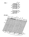
- a stacked, tandem, or cascade-type, photovoltaic device formed of successive n-i-p layers each including an amorphous semiconductor alloy, is shown generally by the reference numeral 10.
- the large area photovoltaic power module of the present invention may include photovoltaic cells having a similar configuration; however, it is to be understood that the instant invention is not limited to the use of any particular composition or configuration of cell or layers.
- any other type of thin film solar cells such as p-i-n devices, p-n devices, Schottky barrier devices or MIS (metal-insulator-semiconductor) type cells formed of silicon alloys, germanium alloys, silicon-germanium alloys, cadmium telluride, cadmium sulfide, cadmium selenide, gallium arsenide copper indium diselenide and the like may also be employed in the fabrication of modules in accord with the principles of the instant invention.
- MIS metal-insulator-semiconductor
- Figure 1 shows a tandem photovoltaic device 10, which includes a photovoltaic semiconductor body 12 adapted to generate a flow of electrical current in response to the absorption of photons incident thereupon, and consisting of a plurality of n-i-p photovoltaic cells 12 a , 12 b , and 12 c .
- a flexible substrate 11 which may be a metallic member such as an electrically conductive stainless steel sheet, or a thin metallic foil, or which may be formed from an electrically insulating material such as glass, synthetic polymeric resins and the like, and provided with an electrically conductive coating upon at least a portion thereof.
- substrate shall also include any elements added thereto by preliminary processing.
- each of cells 12 a , 12 b and 12 c includes a semiconductor body containing at least a silicon alloy.
- Each of the alloy bodies includes an n-type region or layer (16 a , 16 b and 16 c ); an intrinsic region or layer (18 a , 18 b and 18 c ); and a p-type region or layer (20 a , 20 b and 20 c ).
- cell 12 b is an intermediate cell and, as indicated in Figure 1, additional intermediate cells may be stacked atop the illustrated cells without departing from the spirit or scope of the present invention.
- n-i-p type cell as used herein is meant to include any triad of n, i and p semiconductor layers operatively disposed to provide a photoactive region for generating charge carriers in response to the absorption of photon energy.
- the p-type layers are characterized by low light absorption, high conductivity, layers of preferably microcrystalline, semiconductor alloy material.
- the intrinsic alloy layers are characterized by an adjusted wavelength threshold for a solar photoresponse, high light absorption, low dark conductivity and high photoconductivity and may include sufficient amounts of a band gap adjusting element or elements to optimize the band gap for the particular cell application.
- the intrinsic layers are band gap adjusted to provide cell 12 a with a lowest band gap, cell 12 c with the highest band gap, and cell 12 b with a band gap between the other two.
- the n-type layers are characterized by low light absorption, high conductivity, preferably microcrystalline, alloy layers.
- the thickness of the n-type layers is preferably in the range of about 25 to 500 angstroms.
- the thickness of the band gap adjusted, amorphous intrinsic alloy layers is preferably between about 2,000 angstroms to 30,000 angstroms.
- the thickness of the p-type layers is preferably between 25 to 500 angstroms.
- the photovoltaic device 10 further includes a layer of transparent electrically conductive material 22, which serves as the top electrode of the photovoltaic device.
- This layer 22 may be deposited over the semiconductor body 12 in a continuous process, or in a separate environment.
- the transparent conductive layer 22 is formed of indium tin oxide although other transparent conductive materials such as zinc oxide, cadmium stannate, tin oxide and indium oxide are known to skilled practitioners and may also be suitably employed to form the layer.
- the photovoltaic device 10, may also include a bus-grid pattern 24 formed of a highly conductive material to assist in the collection of photogenerated current.
- the bus-grid pattern is typically formed of a metal such as copper on silver.
- FIG. 2A there is shown a plan view of a stowable, deployable large area solar module 30 structured in accord with the principles of the instant invention.
- the module 30 of Figure 2A includes four mechanically and electrically interconnected large area photovoltaic panels 32, 34, 36 and 38.
- each of the panels 32 - 38 are formed of thin film photovoltaic material generally similar to that illustrated with reference to Figure 1.
- Each of the large area panels 32 - 38 is a lightweight, flexible, photovoltaic panel comprised of thin film alloy materials, and each of the large area panels 32 - 38 includes thereon a bus-grid pattern 40 to aid in the collection of photogenerated current.
- the photovoltaic material of the large area panels it is preferable to subdivide the photovoltaic material of the large area panels into a plurality of smaller area, electrically interconnected segments so as to provide the panel with a degree of defect and damage tolerance and to optimize the voltage and current output thereof.
- the module of the instant invention may be fabricated with any combination of differently or similarly configured, interconnected panels, the only requirement being that the electrical outputs of the panels be electrically compatible.
- Each of the large area panels 32 - 38 will also preferably be encapsulated in a protective coating so as to prevent damage to the thin semiconductor layers. It is preferred that at least the light incident surface of the large area panels 32 - 38 be protected with a light flexible transparent coating or protective member such as polyesters, fluoropolymers, polyimides and other synthetic organic polymers.
- the protective member may preferably be a transparent inorganic material such as silicon dioxide, silicon nitride or silicon oxynitride.
- a flexible hinge 42 mechanically interconnecting adjacent large area panels 32 - 38.
- the hinge 42 allows for the panels 32 - 38 to be folded in overlying sandwiched relationship with one another, additionally since the hinge 42 is flexible it allows for the sandwiched panels to be helically wound into a cylindrical configuration which may be readily stowed.
- the hinge 42 is formed at least partially of a flexible material.
- the hinge 42 may in some instances be formed of a synthetic polymeric material such as polypropelene, polyacetate and the like. In other instances, the hinge may be formed of thin metal, various woven fabrics, cardboard, fiberboard and so forth.
- the large area module 30 may also preferably include a reinforcing binding member or tape 44 disposed about the periphery thereof for providing additional strength and rigidity to the module.
- This binding member 44 may be a fabric or plastic tape or a relatively thin flexible plastic or metallic molding extending about the periphery of the module 30.
- the reinforcing member 44 may include one or more grommets 46 therein to be utilized for purposes of deploying the module 30 for operation.
- the grommets 46 will preferably be located at least in the corners of the module 30, although they may in some instances be elsewhere disposed.
- the module may also include one or more reinforcing or stiffening members 45 disposed upon the periphery of the module 30 and bridging the hinged portion of adjacent panels.
- the stiffening member 45 has been found advantageous in maintaining integrity of the deployed module 30.
- the stiffening member 45 may be a rigid or semirigid metallic or polymeric member affixed to the module, by snaps, hooks, loops or by a Velcro backing. In some instances, the Velcro material itself confers sufficient rigidity to the module.
- each of the large area panels 32 - 38 has associated therewith an electrical terminal 48 electrically communicating with the photovoltaic material of the panel for withdrawing electrical power therefrom.
- the terminal 48 may comprise a simple pair of wires or may include any one of the many electrical couplers or plugs well known and available to those skilled in the arts.
- the electrical power produced by each of the large area panels 32 - 38 may be separately utilized by different appliances or for different purposes; or, as depicted in the Figure, the terminals 48 of the various panels 32 - 38 may be electrically interconnected to provide a unitary electrical outlet to a single module terminal 50 adapted for interconnection with a power needy appliance or other such load.
- the large area panels 32 - 38 are electrically interconnected in a series relationship. However, it should be immediately apparent that parallel and mixed series - parallel arrangements of panel interconnections may also be established.
- FIG. 2B there is illustrated the manner in which the module 30 of Figure 2A may be compacted for storage.
- the module 30 is first folded in half so that panels 36 and 38 overlie panels 32 and 34.
- the module 30 is again folded in the manner of a road map so that the panels 32 - 38 are in stacked superposed relationship.
- the module terminal 50 is placed atop the topmost panel 34, and the module is now ready to be rolled up.
- FIG. 2D there is shown the rolling of the folded module 30. Beginning at one of the narrow ends, the folded module is helically wound into a compact form for storage. It should be noted at this point that the terms "rolling” or “helically winding” as used herein shall refer to any process whereby the folded module is compacted so that the stacked panels assume a generally helical form. Rolling shall include both spirally winding the module into a cylindrical configuration as well as folding the stacked panels loosely. As depicted in Figure 2D, in phantom outline, a lightweight form 47 made of polymeric foam, wood or other such material may be used to enable the module to be rolled into a compact shape having a generally rectangular cross section.
- a lightweight form 47 made of polymeric foam, wood or other such material may be used to enable the module to be rolled into a compact shape having a generally rectangular cross section.
- Such a rectangularly folded or rolled module is readily adapted for storage in the top or side of a vehicle or in the pocket of a back pack or an article of apparel. While in some instances the module may be simply rolled without encountering any difficulty, in other instances the thickness of the panels and/or the lack of mobility of the hinges 42 in the plane of the panels will cause problems during the rolling.
- this buckling may sometimes be tolerated or accomodated for by loosely rolling the module; however, in those instances where it is desirable to roll the module as compactly as possible for stowage, such buckling would be unacceptable insofar as it would wrinkle or otherwise deform the panel and thereby damage the photovoltaic material.
- a hinge for interconnecting the panels of the module, which hinge allows for (1) the folding of the panels into a sandwich relationship and (2) a degree of planar displacement of the stacked panels relative to one another.
- planar displacement is meant to define relative lateral or longitudinal motion of the panels relative to one another in a plane corresponding to the planar surface of the panels.
- FIG. 3 there is shown an enlarged, detailed depiction of a portion of a flexible hinge structured in accord with the principles of the instant invention as adapted to interconnect two adjacent large area solar panels in a manner which allows for a degree of planar displacement of said panels.
- a flexible hinge 52 As illustrated in the Figure, there are two portions of adjacent large area panels 32', 34' generally similar to those depicted with reference to Figure 2, jointed by a flexible hinge 52.
- the hinge 52 includes two groups of hinge knuckles 54, and 56.
- the first group of hinge knuckles 54 are associated with the first photovoltaic panel 32' and the second group of hinge knuckles 56 are associated with the second panel 34'.
- Each of the hinge knuckles is formed of a relatively flexible material such as cloth, thin metal, synthetic polymeric material, rubber and the like and includes a passage therethrough adapted to receive and retain a pintle or hinge pin. It will be noted from the figure that the hinge knuckles are disposed in a spaced apart, generally coplanar interdigitating relationship.
- the hinge knuckles associated with each of the two panels 32' and 34' alternate with one another and each of the hinge knuckles 54, 56 are somewhat smaller than the space formed by the two hinge knuckles on the adjoining panel.
- the hinge knuckles 56 a , 56 b of the second panel 34' are spaced far enough apart so that the hinge knuckle 54 b of the first panel 32' can fit therebetween without occupying the entirety of that space; this feature is essential for allowing for the relative planar displacement of the two panels 32', 34' when they are rolled.
- a flexible pintle 58 is disposed so as to sequentially pass through alternating ones of the hinge knuckles so as to "lace" together the two panels 32', 34'.
- the pintle 58 first passes through hinge knuckle 54 a then through hinge knuckle 56 a then back through hinge knuckle 54 b and on through hinge knuckle 56 b and so forth in sequence.
- the pintle 58 is an elongated member having a cross sectional dimension substantially smaller than its linear dimension. It may be configured to have a circular, oval, square or flat cross section and is desirably fabricated from a somewhat rigid but flexible material.
- polypropylene fiber of approximately two millimeters diameter; other materials which may be used with equal advantage include by way of illustration: thin flexible metals, helically wound, elongated springs, cloth, leather, rubber, or synthetic polymeric materials.
- the hinge knuckles 54, 56 may be formed of a flexible material adhesively or mechanically affixed to the large area panels 32', 34'.
- the hinge knuckles 54, 56 may be formed from a portion of the encapsulating material used to protect the panels 32', 34' by extending that encapsulant material beyond the edge of the panel, folding it over to the opposite base of the panel so as to define a passageway proximate the fold and cutting the folded over portion so at to define the hinge knuckles.
- the hinge knuckles may comprise circular or cylindrical members formed of metal or other rigid material spacedly mounted on the periphery of the panels. Many other such variations should be readily apparent to one skilled in the art.
- hinge 52 of Figure 3 was depicted as having hinge knuckles disposed in spaced apart relationship, other designs could similary be employed to allow for planar displacement of the panels.
- the hinge knuckles may be of a tapering shape, all such variations being within the scope of the instant invention.
- FIG. 4 there is shown a lightweight support member 60 which may be adapted to deploy a solar power module, such as that illustrated with reference to Figure 2A, in an orientation and configuration for illumination thereof.
- the support member 60 of Figure 4 includes two flexible, rod-like members 62, 64 joined at their centers by a fixture 66.
- the two rods 62,64 are flexible and preferably formed of: a fiberglass composite, thin metal tubing or limber pieces of wood and are adapted to engage the four corners of a large area solar module (30, indicated here in phantom outline) and maintain that module under a degree of tautness.
- the module 30 may be readily oriented for maximum insolation by disposing the framework 60 on a surface such as the earth and tilting it toward the sun. When the proper orientation is obtained, the framework 60 and module 30 may be immobilized by placing weights upon the rods 62, 64 where they contact the earth or by using light lines and stakes to immobilize the framework 60. It will be noted that the rods 62, 64 and the joint 66 generally resemble the framework of currently employed tents.
- the rods 62, 64 may be disassemblable in the manner of employed tent frames and may be advantageously manufactured from lightweight metal, polymeric or composite materials presently utilized.
- the module 30 may be mounted on the outside of, or from one or more walls of at tent or similar structure.
- the framework 60 may be dispensed with and the module 30 hung on a structure or staked to the ground.
- FIG. 5 there is shown a storage cannister 70 having retained therein the helically rolled large area photovoltaic power module 30 of the instant invention, illustrating one mode of stowage which the module of the instant invention may be adapted for.
- the cannister 70 of Figure 5 is preferably formed of lightweight, durable materials such as metal, plastics, canvas and the like, which are resistant to environmental degradation.
- the cannister 70 further includes a cap 72 for enclosing the module.
- the cannister 70 may be further adapted to stow additional components such as the framework 60 of Figure 4.
- the framework 60 may be disassembled into a plurality of small portions which may be inserted into the center of the helically wound module 30.
- the cannister 70 may be provided with an additional storage compartment adapted to retain such ancillary equipment.
- a storage container appropriately configured will be employed.
Landscapes
- Photovoltaic Devices (AREA)
Priority Applications (1)
| Application Number | Priority Date | Filing Date | Title |
|---|---|---|---|
| AT86113550T ATE75347T1 (de) | 1985-10-21 | 1986-10-02 | Verstaubarer grossflaechiger solargeneratormodul. |
Applications Claiming Priority (2)
| Application Number | Priority Date | Filing Date | Title |
|---|---|---|---|
| US06/789,906 US4713492A (en) | 1985-10-21 | 1985-10-21 | Stowable large area solar power module |
| US789906 | 1985-10-21 |
Publications (3)
| Publication Number | Publication Date |
|---|---|
| EP0219734A2 true EP0219734A2 (de) | 1987-04-29 |
| EP0219734A3 EP0219734A3 (en) | 1989-05-24 |
| EP0219734B1 EP0219734B1 (de) | 1992-04-22 |
Family
ID=25149062
Family Applications (1)
| Application Number | Title | Priority Date | Filing Date |
|---|---|---|---|
| EP86113550A Expired - Lifetime EP0219734B1 (de) | 1985-10-21 | 1986-10-02 | Verstaubarer grossflächiger Solargeneratormodul |
Country Status (6)
| Country | Link |
|---|---|
| US (1) | US4713492A (de) |
| EP (1) | EP0219734B1 (de) |
| JP (1) | JPH0746733B2 (de) |
| AT (1) | ATE75347T1 (de) |
| CA (1) | CA1274307A (de) |
| DE (1) | DE3684984D1 (de) |
Cited By (6)
| Publication number | Priority date | Publication date | Assignee | Title |
|---|---|---|---|---|
| DE4433769A1 (de) * | 1994-09-22 | 1996-03-28 | Blue Planet Ag | Verfahren zum Befestigen von Solarplatten |
| DE19944414A1 (de) * | 1999-09-16 | 2001-04-05 | Daimler Chrysler Ag | Verschaltung von leitfähigen Rückseiten eines flexiblen Solargenerators |
| DE102008045997A1 (de) | 2007-10-23 | 2009-04-30 | Bluenergy Ag | Verkapselte Solarzelle |
| GB2478907A (en) * | 2010-03-22 | 2011-09-28 | Avencroft Ltd | Modular construction panel formed from recycled rubber particles |
| EP3457562A4 (de) * | 2016-05-11 | 2019-05-01 | Mitsubishi Electric Corporation | Fotovoltaische erzeugungsvorrichtung, solarbatteriepaddel und raumstruktur |
| US20190267932A1 (en) * | 2017-09-21 | 2019-08-29 | Tesla, Inc. | Hinged building integrated photovoltaic roof tile modules |
Families Citing this family (78)
| Publication number | Priority date | Publication date | Assignee | Title |
|---|---|---|---|---|
| US5212916A (en) * | 1984-07-26 | 1993-05-25 | Peter Raupach | Device for shading spaces |
| DE3427574A1 (de) * | 1984-07-26 | 1986-02-06 | Stromeyer Ingenieurbau GmbH, 7750 Konstanz | Vorrichtung zur beschattung von flaechen |
| USD303244S (en) | 1987-12-04 | 1989-09-05 | Energy Conversion Devices, Inc. | Combined flexible solar cell panel and deployment/storage mast |
| JPH0744028Y2 (ja) * | 1989-11-13 | 1995-10-09 | 大阪チタニウム製造株式会社 | 太陽電池ユニット |
| JP2557809B2 (ja) * | 1989-12-04 | 1996-11-27 | 株式会社フジタ | 太陽電池を具備したエアドーム |
| DE4142566C2 (de) * | 1990-12-28 | 1998-09-10 | Webasto Systemkomponenten Gmbh | Solaranlage mit auf einem räumlich gekrümmten Tragwerk angeordneten Solarmodulen |
| US5246506A (en) * | 1991-07-16 | 1993-09-21 | Solarex Corporation | Multijunction photovoltaic device and fabrication method |
| US5244508A (en) * | 1992-04-02 | 1993-09-14 | The United States Of America As Represented By The Administrator Of The National Aeronautics And Space Administration | Self-deploying photovoltaic power system |
| DE4436246A1 (de) * | 1994-10-11 | 1996-04-18 | Putzmeister Maschf | Oberbekleidungsstück |
| TW280962B (en) * | 1995-02-24 | 1996-07-11 | Sanyo Electric Co | Battery charger and a solar battery used for charging a battery |
| US5543730A (en) * | 1995-05-17 | 1996-08-06 | Altera Corporation | Techniques for programming programmable logic array devices |
| US5605769A (en) * | 1995-07-03 | 1997-02-25 | Toms; Dennis J. | Method and apparatus for supplying electrical energy to battery powered equipment |
| DE29824045U1 (de) | 1998-06-26 | 2000-03-30 | alwitra GmbH & Co Klaus Göbel, 54296 Trier | Dachbahn für Dachabdichtungen zum Schutz eines Bauwerks |
| US6147294A (en) * | 1999-04-06 | 2000-11-14 | Trw Inc. | D-wing deployable solar array |
| US6295818B1 (en) * | 1999-06-29 | 2001-10-02 | Powerlight Corporation | PV-thermal solar power assembly |
| US20050126628A1 (en) * | 2002-09-05 | 2005-06-16 | Nanosys, Inc. | Nanostructure and nanocomposite based compositions and photovoltaic devices |
| US7806370B2 (en) * | 2006-03-31 | 2010-10-05 | Composite Technology Development, Inc. | Large-scale deployable solar array |
| US8376282B2 (en) | 2006-03-31 | 2013-02-19 | Composite Technology Development, Inc. | Collapsible structures |
| US8109472B1 (en) | 2006-03-31 | 2012-02-07 | Composite Technology Development, Inc. | Collapsible structures with adjustable forms |
| US8387921B2 (en) * | 2006-03-31 | 2013-03-05 | Composite Technology Development, Inc. | Self deploying solar array |
| US20080202498A1 (en) * | 2007-02-28 | 2008-08-28 | Victor Manuel Ramos | Self-sufficient portable heating system using renewable energy |
| US20080266758A1 (en) * | 2007-04-25 | 2008-10-30 | Hurt Steven B | Mobile utilities station |
| US20090178701A1 (en) * | 2007-09-21 | 2009-07-16 | Solyndra, Inc. | Apparatus and methods for sealing an electrical connection to at least one elongated photovoltaic module |
| US20090320898A1 (en) * | 2008-01-10 | 2009-12-31 | Gumm Michael L | Configurable Articulated Photovoltaic Assembly |
| US20090178703A1 (en) * | 2008-01-10 | 2009-07-16 | Gumm Michael L | Configurable Articulated Photovoltaic Assembly |
| CA2716361A1 (en) | 2008-02-28 | 2009-09-03 | New Millennium Solar Equipment Corp. | Insulating glass unit with integrated mini-junction device |
| US20090288891A1 (en) * | 2008-05-20 | 2009-11-26 | Paul Budge | Apparatus, system, and method for expandable photovoltaic panel electricity generation |
| US20090314327A1 (en) * | 2008-06-24 | 2009-12-24 | Moser Baer Photovoltaic Limited | Photovoltaic module |
| US20090314326A1 (en) * | 2008-06-24 | 2009-12-24 | Moser Baer Photovoltaic Limited | Photovoltaic module |
| US20100031996A1 (en) * | 2008-08-11 | 2010-02-11 | Basol Bulent M | Structure and method of manufacturing thin film photovoltaic modules |
| US8096294B1 (en) * | 2008-10-08 | 2012-01-17 | Jenkins Richard D | Spa water heating apparatus and method |
| US20100154860A1 (en) * | 2008-12-01 | 2010-06-24 | Tom Ferghana Rogers Fereday | Collapsible stand for rollable solar panel |
| US8314324B2 (en) | 2008-12-19 | 2012-11-20 | Shadeplex, Llc | Laminated thin film photovoltaic systems |
| US9281569B2 (en) | 2009-01-29 | 2016-03-08 | Composite Technology Development, Inc. | Deployable reflector |
| US8418418B2 (en) | 2009-04-29 | 2013-04-16 | 3Form, Inc. | Architectural panels with organic photovoltaic interlayers and methods of forming the same |
| US9140468B2 (en) * | 2009-05-07 | 2015-09-22 | Michael Lee Gomery | Solar power unit |
| KR101074782B1 (ko) * | 2009-12-01 | 2011-10-19 | 삼성에스디아이 주식회사 | 염료감응 태양전지 모듈 |
| US20110162690A1 (en) * | 2010-01-06 | 2011-07-07 | Goal Zero Llc | Transportable solar panel and support system |
| US8683755B1 (en) * | 2010-01-21 | 2014-04-01 | Deployable Space Systems, Inc. | Directionally controlled elastically deployable roll-out solar array |
| WO2011109275A1 (en) * | 2010-03-03 | 2011-09-09 | Composite Technology Development, Inc. | Deployable structures having collapsible structural members |
| JP5516115B2 (ja) * | 2010-06-18 | 2014-06-11 | 株式会社オーエスエム | 携帯型太陽光発電装置 |
| WO2012063234A1 (en) * | 2010-11-08 | 2012-05-18 | Chaimovski, Dan | Portable folding solar panels |
| US8756880B2 (en) * | 2010-12-03 | 2014-06-24 | Shadeplex, Llc | Photovoltaic module assembly |
| WO2012103446A2 (en) | 2011-01-28 | 2012-08-02 | Korman Bette | Modular portable energy system |
| US8863741B2 (en) * | 2011-04-08 | 2014-10-21 | Cameron R MacKay | Solar air heating device |
| EP2754186B1 (de) | 2011-09-06 | 2019-02-06 | Suntube Holding APS | Zusammenlegbares photovoltaik-modul für solarstromgrossanlage und verfahren für dessen montage |
| US10090799B2 (en) * | 2012-01-10 | 2018-10-02 | Pvilion, Inc. | Tensioned sheet-metal based solar panels and structures for supporting the same |
| US9742348B2 (en) | 2013-09-16 | 2017-08-22 | Brigham Young University | Foldable array of three-dimensional panels including functional electrical components |
| WO2015077363A1 (en) * | 2013-11-20 | 2015-05-28 | Brigham Young University | Rigidly foldable array of three-dimensional bodies |
| US12021162B2 (en) | 2014-06-02 | 2024-06-25 | California Institute Of Technology | Ultralight photovoltaic power generation tiles |
| USD755118S1 (en) | 2014-10-08 | 2016-05-03 | Composite Technology Development, Inc. | Trifold solar panel |
| USD751498S1 (en) | 2014-10-08 | 2016-03-15 | Composite Technology Development, Inc. | Trifold solar panel |
| USD755119S1 (en) | 2014-10-08 | 2016-05-03 | Composite Technology Development, Inc. | Trifold solar panel |
| USD754598S1 (en) | 2014-10-08 | 2016-04-26 | Composite Technology Development, Inc. | Trifold solar panel |
| JP6476740B2 (ja) | 2014-10-23 | 2019-03-06 | 住友電気工業株式会社 | 太陽光発電パネルおよび太陽光発電装置の製造方法 |
| US9004410B1 (en) | 2014-10-24 | 2015-04-14 | Alliance Spacesystems, Llc | Deployable boom for collecting electromagnetic energy |
| US10059471B2 (en) | 2014-10-24 | 2018-08-28 | Solaero Technologies Corp. | Method for releasing a deployable boom |
| IL236578A (en) * | 2015-01-04 | 2016-02-29 | Emanuele Rossi | Folding sunshade |
| JP6715317B2 (ja) * | 2015-07-22 | 2020-07-01 | カリフォルニア インスティチュート オブ テクノロジー | コンパクトパッケージング用の大面積構造体 |
| US10454565B2 (en) | 2015-08-10 | 2019-10-22 | California Institute Of Technology | Systems and methods for performing shape estimation using sun sensors in large-scale space-based solar power stations |
| US10992253B2 (en) | 2015-08-10 | 2021-04-27 | California Institute Of Technology | Compactable power generation arrays |
| US20170279402A1 (en) * | 2016-03-25 | 2017-09-28 | X Development Llc | Photovoltaic macro-module for solar power generation |
| USD778234S1 (en) * | 2016-03-29 | 2017-02-07 | SBM Solar, Inc. | Foldable solar panel |
| US20170310272A1 (en) * | 2016-04-25 | 2017-10-26 | Google Inc. | Floating photovoltaic power generation system |
| IT201600107594A1 (it) * | 2016-10-25 | 2018-04-25 | Agatos Energia Srl | Pannello fotovoltaico avente una struttura flessibile e metodo di fabbricazione relativo. |
| US11159121B2 (en) * | 2017-01-25 | 2021-10-26 | FSWM Technical Enterprises, Inc. | Deployable land-based solar energy collection system |
| AU2018265262A1 (en) * | 2017-05-12 | 2019-11-21 | Maxeon Solar Pte. Ltd. | Folding photovoltaic panel |
| USD921573S1 (en) | 2018-06-15 | 2021-06-08 | Sunpower Corporation | Photovoltaic panel system |
| US10581372B2 (en) | 2018-06-15 | 2020-03-03 | Sunpower Corporation | Photovoltaic panel |
| US11772826B2 (en) | 2018-10-31 | 2023-10-03 | California Institute Of Technology | Actively controlled spacecraft deployment mechanism |
| US10811759B2 (en) | 2018-11-13 | 2020-10-20 | Eagle Technology, Llc | Mesh antenna reflector with deployable perimeter |
| US20240266454A1 (en) * | 2018-12-27 | 2024-08-08 | Solarpaint Ltd. | Flexible and Rollable Self-Floating and Self-Buoyant Solar Panels and Photovoltaic Devices |
| US11139549B2 (en) | 2019-01-16 | 2021-10-05 | Eagle Technology, Llc | Compact storable extendible member reflector |
| US10797400B1 (en) | 2019-03-14 | 2020-10-06 | Eagle Technology, Llc | High compaction ratio reflector antenna with offset optics |
| US11784267B2 (en) * | 2019-10-29 | 2023-10-10 | Sun Hunter Inc. | CIGS lamination structure and portable solar charger using same |
| CN111874455A (zh) * | 2020-07-28 | 2020-11-03 | 光能动力(北京)科技有限责任公司 | 柔性太阳能组件的运输方式 |
| EP4462488A1 (de) * | 2023-05-09 | 2024-11-13 | Sono Motors GmbH | Vormontiertes solarblech zur montage an einer tragstruktur |
| US12689319B2 (en) | 2024-05-15 | 2026-07-21 | Solar Stik, Inc. | Modular solar panel enclosure |
Family Cites Families (8)
| Publication number | Priority date | Publication date | Assignee | Title |
|---|---|---|---|---|
| US3165751A (en) * | 1962-10-26 | 1965-01-12 | Westinghouse Electric Corp | Rolled passive reflective antenna tending to unroll under bias of entrapped air |
| US3690080A (en) * | 1970-09-21 | 1972-09-12 | Trw Inc | Solar array with self-erecting, self-rigidizing roll-up sheets |
| US4119965A (en) * | 1977-08-08 | 1978-10-10 | Philip Kaszyk | Radar reflector |
| US4282394A (en) * | 1979-10-24 | 1981-08-04 | The Boeing Company | Underwing reflector solar array |
| FR2525393A1 (fr) * | 1982-04-17 | 1983-10-21 | Licentia Gmbh | Generateur pliable a cellules solaires |
| US4485264A (en) * | 1982-11-09 | 1984-11-27 | Energy Conversion Devices, Inc. | Isolation layer for photovoltaic device and method of producing same |
| US4565607A (en) * | 1984-03-09 | 1986-01-21 | Energy Conversion Devices, Inc. | Method of fabricating an electroplated substrate |
| US4530739A (en) * | 1984-03-09 | 1985-07-23 | Energy Conversion Devices, Inc. | Method of fabricating an electroplated substrate |
-
1985
- 1985-10-21 US US06/789,906 patent/US4713492A/en not_active Expired - Lifetime
-
1986
- 1986-09-25 CA CA000519111A patent/CA1274307A/en not_active Expired - Lifetime
- 1986-10-02 AT AT86113550T patent/ATE75347T1/de not_active IP Right Cessation
- 1986-10-02 EP EP86113550A patent/EP0219734B1/de not_active Expired - Lifetime
- 1986-10-02 DE DE8686113550T patent/DE3684984D1/de not_active Expired - Fee Related
- 1986-10-21 JP JP61250606A patent/JPH0746733B2/ja not_active Expired - Lifetime
Cited By (8)
| Publication number | Priority date | Publication date | Assignee | Title |
|---|---|---|---|---|
| DE4433769A1 (de) * | 1994-09-22 | 1996-03-28 | Blue Planet Ag | Verfahren zum Befestigen von Solarplatten |
| DE19944414A1 (de) * | 1999-09-16 | 2001-04-05 | Daimler Chrysler Ag | Verschaltung von leitfähigen Rückseiten eines flexiblen Solargenerators |
| US6320114B1 (en) | 1999-09-16 | 2001-11-20 | Daimlerchrysler Ag | Solar generator with electrically conducting hinges |
| DE102008045997A1 (de) | 2007-10-23 | 2009-04-30 | Bluenergy Ag | Verkapselte Solarzelle |
| GB2478907A (en) * | 2010-03-22 | 2011-09-28 | Avencroft Ltd | Modular construction panel formed from recycled rubber particles |
| EP3457562A4 (de) * | 2016-05-11 | 2019-05-01 | Mitsubishi Electric Corporation | Fotovoltaische erzeugungsvorrichtung, solarbatteriepaddel und raumstruktur |
| US20190267932A1 (en) * | 2017-09-21 | 2019-08-29 | Tesla, Inc. | Hinged building integrated photovoltaic roof tile modules |
| US10855220B2 (en) * | 2017-09-21 | 2020-12-01 | Tesla, Inc. | Hinged building integrated photovoltaic roof tile modules |
Also Published As
| Publication number | Publication date |
|---|---|
| EP0219734A3 (en) | 1989-05-24 |
| CA1274307A (en) | 1990-09-18 |
| JPS6298781A (ja) | 1987-05-08 |
| US4713492A (en) | 1987-12-15 |
| JPH0746733B2 (ja) | 1995-05-17 |
| ATE75347T1 (de) | 1992-05-15 |
| EP0219734B1 (de) | 1992-04-22 |
| DE3684984D1 (de) | 1992-05-27 |
Similar Documents
| Publication | Publication Date | Title |
|---|---|---|
| EP0219734B1 (de) | Verstaubarer grossflächiger Solargeneratormodul | |
| US6188012B1 (en) | Methods and systems for a solar cell concentrator | |
| CN110383678B (zh) | 具有非垂直互连的可折叠光伏组件 | |
| US20120090659A1 (en) | Portable solar panel array | |
| US5885367A (en) | Retractable thin film solar concentrator for spacecraft | |
| US8376282B2 (en) | Collapsible structures | |
| US9391457B2 (en) | Apparatus and method for producing AC power | |
| US20110277809A1 (en) | Modular Tensile Structure with Integrated Photovoltaic Modules | |
| CA2622620A1 (fr) | Store ou velum photo-generateur | |
| Ghosh et al. | Achieving over 30% efficiency employing a novel double absorber solar cell configuration integrating Ca3NCl3 and Ca3SbI3 perovskites | |
| EP0984511A2 (de) | Kombinierter RF-Reflektor mit Solarzellenarray | |
| Nocito et al. | Flexible photovoltaic cells embedded into textile structures | |
| JP2003318430A (ja) | 太陽電池モジュールとその設置方法 | |
| WO2013009707A2 (en) | Foldable, portable, lightweight photovoltaic module | |
| WO2011006506A1 (en) | Foldable frame supporting electromagnetic radiation collectors | |
| US20170152837A1 (en) | Portable power generating solar cell wind turbine | |
| US20190288137A1 (en) | Rollable solar power module with in-plane interconnects | |
| JP4325213B2 (ja) | 可搬型太陽電池パネル | |
| US20180122972A1 (en) | Semi-flexible solar module using crystaline solar cells and method for fabrication thereof | |
| WO2022208498A1 (en) | Flexible and rollable self-floating and self-buoyant solar panels and photovoltaic devices | |
| RU198984U1 (ru) | Бинарный космический аппарат с реконфигурируемой антенной, совмещенной со свертываемой в рулон солнечной батареей, развертываемой мультивекторными матричными ракетными двигателями | |
| CH708997A2 (fr) | Panneau photovoltaïque pour parasol. | |
| KR101935305B1 (ko) | 해양플랜트용 태양전지 발전장치 | |
| CN115668753A (zh) | 三浦折纸法光伏模块 | |
| WO2019144586A1 (zh) | 太阳能发电装置 |
Legal Events
| Date | Code | Title | Description |
|---|---|---|---|
| PUAI | Public reference made under article 153(3) epc to a published international application that has entered the european phase |
Free format text: ORIGINAL CODE: 0009012 |
|
| AK | Designated contracting states |
Kind code of ref document: A2 Designated state(s): AT BE CH DE ES FR GB GR IT LI LU NL SE |
|
| PUAL | Search report despatched |
Free format text: ORIGINAL CODE: 0009013 |
|
| AK | Designated contracting states |
Kind code of ref document: A3 Designated state(s): AT BE CH DE ES FR GB GR IT LI LU NL SE |
|
| 17P | Request for examination filed |
Effective date: 19891004 |
|
| 17Q | First examination report despatched |
Effective date: 19910419 |
|
| ITTA | It: last paid annual fee | ||
| GRAA | (expected) grant |
Free format text: ORIGINAL CODE: 0009210 |
|
| AK | Designated contracting states |
Kind code of ref document: B1 Designated state(s): AT BE CH DE ES FR GB GR IT LI LU NL SE |
|
| ITF | It: translation for a ep patent filed | ||
| PG25 | Lapsed in a contracting state [announced via postgrant information from national office to epo] |
Ref country code: BE Effective date: 19920422 Ref country code: GR Free format text: LAPSE BECAUSE OF FAILURE TO SUBMIT A TRANSLATION OF THE DESCRIPTION OR TO PAY THE FEE WITHIN THE PRESCRIBED TIME-LIMIT Effective date: 19920422 Ref country code: LI Effective date: 19920422 Ref country code: CH Effective date: 19920422 Ref country code: SE Effective date: 19920422 Ref country code: AT Effective date: 19920422 |
|
| REF | Corresponds to: |
Ref document number: 75347 Country of ref document: AT Date of ref document: 19920515 Kind code of ref document: T |
|
| REF | Corresponds to: |
Ref document number: 3684984 Country of ref document: DE Date of ref document: 19920527 |
|
| ET | Fr: translation filed | ||
| REG | Reference to a national code |
Ref country code: CH Ref legal event code: PL |
|
| PG25 | Lapsed in a contracting state [announced via postgrant information from national office to epo] |
Ref country code: ES Free format text: LAPSE BECAUSE OF FAILURE TO SUBMIT A TRANSLATION OF THE DESCRIPTION OR TO PAY THE FEE WITHIN THE PRESCRIBED TIME-LIMIT Effective date: 19920802 |
|
| PG25 | Lapsed in a contracting state [announced via postgrant information from national office to epo] |
Ref country code: LU Free format text: LAPSE BECAUSE OF NON-PAYMENT OF DUE FEES Effective date: 19921031 |
|
| PLBE | No opposition filed within time limit |
Free format text: ORIGINAL CODE: 0009261 |
|
| STAA | Information on the status of an ep patent application or granted ep patent |
Free format text: STATUS: NO OPPOSITION FILED WITHIN TIME LIMIT |
|
| 26N | No opposition filed | ||
| PG25 | Lapsed in a contracting state [announced via postgrant information from national office to epo] |
Ref country code: NL Effective date: 19930501 |
|
| NLV4 | Nl: lapsed or anulled due to non-payment of the annual fee | ||
| REG | Reference to a national code |
Ref country code: GB Ref legal event code: IF02 |
|
| PGFP | Annual fee paid to national office [announced via postgrant information from national office to epo] |
Ref country code: DE Payment date: 20021031 Year of fee payment: 17 |
|
| PG25 | Lapsed in a contracting state [announced via postgrant information from national office to epo] |
Ref country code: DE Free format text: LAPSE BECAUSE OF NON-PAYMENT OF DUE FEES Effective date: 20040501 |
|
| PGFP | Annual fee paid to national office [announced via postgrant information from national office to epo] |
Ref country code: GB Payment date: 20050914 Year of fee payment: 20 |
|
| PG25 | Lapsed in a contracting state [announced via postgrant information from national office to epo] |
Ref country code: IT Free format text: LAPSE BECAUSE OF NON-PAYMENT OF DUE FEES;WARNING: LAPSES OF ITALIAN PATENTS WITH EFFECTIVE DATE BEFORE 2007 MAY HAVE OCCURRED AT ANY TIME BEFORE 2007. THE CORRECT EFFECTIVE DATE MAY BE DIFFERENT FROM THE ONE RECORDED. Effective date: 20051002 |
|
| PGFP | Annual fee paid to national office [announced via postgrant information from national office to epo] |
Ref country code: FR Payment date: 20051006 Year of fee payment: 20 |
|
| PG25 | Lapsed in a contracting state [announced via postgrant information from national office to epo] |
Ref country code: GB Free format text: LAPSE BECAUSE OF EXPIRATION OF PROTECTION Effective date: 20061001 |
|
| REG | Reference to a national code |
Ref country code: GB Ref legal event code: PE20 |