EP0219754B1 - Jet-Messeranordnung - Google Patents
Jet-Messeranordnung Download PDFInfo
- Publication number
- EP0219754B1 EP0219754B1 EP86113794A EP86113794A EP0219754B1 EP 0219754 B1 EP0219754 B1 EP 0219754B1 EP 86113794 A EP86113794 A EP 86113794A EP 86113794 A EP86113794 A EP 86113794A EP 0219754 B1 EP0219754 B1 EP 0219754B1
- Authority
- EP
- European Patent Office
- Prior art keywords
- channel
- plate
- apertures
- knife
- assembly
- Prior art date
- Legal status (The legal status is an assumption and is not a legal conclusion. Google has not performed a legal analysis and makes no representation as to the accuracy of the status listed.)
- Expired - Lifetime
Links
- 238000004891 communication Methods 0.000 claims abstract description 11
- 239000012530 fluid Substances 0.000 claims description 10
- 239000000047 product Substances 0.000 abstract description 39
- 235000013372 meat Nutrition 0.000 abstract description 13
- 239000002245 particle Substances 0.000 description 5
- 230000002596 correlated effect Effects 0.000 description 3
- 238000004519 manufacturing process Methods 0.000 description 3
- 238000010411 cooking Methods 0.000 description 2
- 230000009977 dual effect Effects 0.000 description 2
- 235000013622 meat product Nutrition 0.000 description 2
- 238000012545 processing Methods 0.000 description 2
- 235000002568 Capsicum frutescens Nutrition 0.000 description 1
- 238000005054 agglomeration Methods 0.000 description 1
- 230000002776 aggregation Effects 0.000 description 1
- 238000013459 approach Methods 0.000 description 1
- 230000000712 assembly Effects 0.000 description 1
- 238000000429 assembly Methods 0.000 description 1
- 230000015572 biosynthetic process Effects 0.000 description 1
- 238000011143 downstream manufacturing Methods 0.000 description 1
- 239000012467 final product Substances 0.000 description 1
- 230000014759 maintenance of location Effects 0.000 description 1
- 238000000034 method Methods 0.000 description 1
- 238000012354 overpressurization Methods 0.000 description 1
- 239000013618 particulate matter Substances 0.000 description 1
- 235000013550 pizza Nutrition 0.000 description 1
- 238000005086 pumping Methods 0.000 description 1
- 238000011160 research Methods 0.000 description 1
- 235000013547 stew Nutrition 0.000 description 1
Images

Classifications
-
- B—PERFORMING OPERATIONS; TRANSPORTING
- B02—CRUSHING, PULVERISING, OR DISINTEGRATING; PREPARATORY TREATMENT OF GRAIN FOR MILLING
- B02C—CRUSHING, PULVERISING, OR DISINTEGRATING IN GENERAL; MILLING GRAIN
- B02C18/00—Disintegrating by knives or other cutting or tearing members which chop material into fragments
- B02C18/30—Mincing machines with perforated discs and feeding worms
Definitions
- the present invention is broadly concerned with reducing apparatus of the type typically used in the production of chunk-type products, e.g., meats used in chilies, stews and as pizza toppings. More particularly, it is concerned with an improved jet- knife apparatus which makes use of a continuous stream of steam or pressurized air in order to forcibly expel product through an apertured plate.
- a wide variety of reducing or comminuting devices have been used in the past to comminute and subdivide meat and other products. These devices vary in complexity and sophistication, depending upon the ultimate product desired. In cases where chunk-type products are to be produced, it has been known to provide grinders equipped with a large circular grinder plate having a series of apertures therethrough, in conjunction with a rotatable, multiple bladed grinder knife. In these devices, incoming product is fed towards and through the grinder plate, and the rotating knife serves to cut the product to a desired size.
- the respective blades are provided with elongated fluid-conveying recesses or channels along the length thereof, and means is provided for delivery of steam or pressurized air to such channels.
- the blades come into communication with the plate apertures, and the pressurized steam or air expels or "pops" the product from the apertures.
- This kind of device has been referred to as a "jet- knife” grinder, and has been used in the production of chunk-type meat products.
- US-A 4 479 614 discloses a meat grinder including a pump that feeds meat particles into a mixing chamber at a constant flow rate. The meat exits into a frustro-conical shaped collection chamber from passage to a grinder plate. A rotating knife with radially extending blades is rotated by a hydraulic motor at a variable rate. The variable flow rate of the particles to chamber and the variable speed of the knife responds in a variable particle size output by the grinder plate.
- a prime drawback of prior jet knife assemblies resides in the fact that they are prone to the production of fines or extra long strings of agglomerated meat particles. Fines in this context refers to particles too small for practical use, whereas strings refers to elongated strands of meat likewise not in optimum condition for use. Fines are typically produced by overpressurization at the plate apertures, whereas strings result from low pressure conditions at the apertures. Such unwanted differential pressures at different apertures may result when a given knife blade channel bridges more than one plate opening during rotation, with the combined areas presented by the opening being greater than the cross-sectional area of the knife blade channel.
- a related difficulty stems from the fact that, with prior jet knife arrangements, the knife operating face on either side of the channel is of insufficient width to completely cover all apertures as the knife rotates. Thus, situations can arise where a given aperture is simultaneously subjected to fluid pressure and to pressure from the stream of product directed towards the plate. This again leads to uneven pressures and the types of problems described above.
- a reducing assembly comprising a plate presenting an inlet face and an outlet face and a plurality of apertures therethrough, a knife including a blade presenting an elongated operating face and structure defining an elongated fluid-conveying channel generally along the length of said operating face and having a closed outermost end, said channel presenting a cross-sectional area taken along a section transverse to the longitudinal axis of said channel, means mounting said knife for rotation thereof proximal to said plate with said blade operating face being adjacent said plate inlet face, and means for introducing pressurized fluid into said channel during rotation of said blade for in turn introducing said fluid from said channel into said apertures during rotation of said blade, characterized in that said channel communicates with successive ones of said apertures during said rotation of said blade such that said channel is in communication with successive aperture-defined open areas, the maximum of said aperture-defined open areas in communication with said channel at any time during rotation of said blade being no greater than a channel cross-
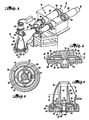
- a product processing assembly 10 which broadly includes a dual piston pump 12 and a jet knife grinder 14 in accordance with the present invention.
- the grinder 14 is operatively coupled to the output of pump 12, in order to receive product and process the same for downstream operations such as cooking.
- the pump 12 is designed to supply a continuous flow of product of pressures of up to about 500 pounds per square inch.
- the depicted pump is manufactured by the Marlen Research Corporation of Overland Park, Kansas.
- the pump 12 includes a pair of pistons 16, 18 that are alternately reciprocal within moveable sleeves 20, 22, respectively.
- Sleeves 20 and 22 are slidable within guide rings 24 and 26, respectively.
- the pistons 16, 18 in the sleeves 20, 22 reciprocate within a feeding chamber (not shown) which has the incoming product fed thereto.
- the output tubes 28, 30 are fed to a mixing chamber 32 including a diverter valve 34 for providing one-way flow from output tubes 28, 30 into mixing chamber 32.
- the sleeve 20 is shifted forwardly (typically by means of conventional hydraulic drive structure) ahead of the pistons 16 to capture a charge of meat or other product within the sleeve and to thereby define a cylinder load.
- the piston 16 is then advanced through the sleeve 20 to create a positive pressure therein, thereby forcibly ejecting the charge of product within the sleeve 20 to the output tube 28 and into mixing chamber 32.
- the sleeve 22 and piston 18 are retracted in the feeding chamber so that product is drawn into the feeding chamber by suction.
- valve 34 is operable to block off flow through the output tube 30 from the mixing chamber 32.
- the grinder 14 is generally of the type described in U. S. Patent No. 4 479 614, and this patent is hereby incorporated by reference herein. Generally, however, the grinder 14 includes a chamber 36 housing an apertured plate 38 and a rotatable knife 40. A variable speed motor 42 also forms a part of the overall assembly, and is coupled by means of a drive assembly 43 to the knife 40 for rotation of the latter.
- the collection chamber 36 is of somewhat frustoconical configuration and has an inlet port 44 and an outlet 46.
- the inlet port 44 is connected to the output of mixing chamber 32 by means of collar 48.
- the walls of chamber 36 taper outwardly from the inlet port and make an essentially right angle bend to the outlet port 46 to provide an overall expanding chamber.
- the collection chamber 36 is thus operable to receive the output of the mixing chamber 32 and allow for an expansion of volume for further processing the meat or other product therein.
- the plate 38 includes an inlet face 50 and an opposed outlet face 52.
- the plate is provided with a single set of circularly arranged, axially extending apertures 54 therethrough. These apertures communicate with an annular recess 56 provided in the outlet face 52 of the plate.
- the plate includes a central, tubular, downwardly extending hub 58 which is important for purposes to be described.
- the plate 38 is maintained in a stationary condition within housing 36 by means of its captive retention between ledge 60 adjacent the lower end of chamber 36, and bottommost connector ring 62 which is threadably secured to the chamber 36 as depicted.
- Knife 40 includes a central hub 64 which presents a square uppermost opening 66 and a circular, central recess 68 adjacent the lower surface thereof. As best seen in Figs. 2 and 4, the recess 68 has a larger diameter than the bore of hub 58.
- the knife 40 also includes a plurality (here four) of radially outwardly extending blades 70 which are integral with hub 64, and, in this embodiment, are equidistantly spaced from one another.
- the blades are identical, and each includes a lowermost operating face 72 presenting an elongated fluid-conveying recess or channel 74 along the length thereof which communicates with central hub recess 68 and a pair of flattened lands 75 on either side of the channel 74.
- the channels 74 are of sufficient length to extend past and cover the apertures 54 during rotation of the knife; and that the width of any land 75 is greater than the diameter of any plate aperture 54.
- the knife is mounted with operating faces 72 of the blades 70 adjacent the inlet or upper face 50 of the plate 38.
- the knife 40 is mounted for rotation about its central axis on a shaft 76 forming a part of the drive assembly 43.
- the shaft 76 includes a square lowermost projection 78 which is received within similarly configured opening 66 of hub 64 to assure a good driving connection.
- the overall drive assembly 43 further includes an elongated, upright, tubular diverter element 80 having recesses 82 adjacent the lower end thereof for receiving the outwardly projecting blades 70.
- the element 80 is centrally bored as illustrated, and receives the shaft 76.
- the element 80 rotates in unison with knife 40, by virtue of the interlocking fit between the element and the blades 70.
- the element 80 includes a tapered, frustoconical outer diversion surface 84 which terminates slightly inboard of the circularly arranged apertures 54. In this fashion, meat or other product delivered to housing 36 is diverted radially outwardly relative to the hub 64 of rotating knife 40, so as to assure even flow of product to the apertures 54.
- Steam or pressurized air is continuously supplied to the grinder assembly, and particularly to the channels 74 of blades 70, through a conduit 86 operably coupled to the lowermost end of tubular hub 58.
- a source of steam or pressurized air (not shown) is operably coupled to the remote end of conduit 86.
- meat or other product is delivered to the inlet 44 of housing 36, and is thence fed under pressure towards plate 38 and knife 40.
- motor 42 is activated in order to rotate the knife 40.
- the product approaches the plate 38, such product is diverted outwardly by means of the diverter element 80 towards and through the apertures 54.
- the blades 70 thereof successively cut or shear the product passing through the apertures 54.
- fluid pressure within the channel serves to expel or "pop" the product from the apertures.
- Fig. 4 where it will be seen that a plug or piece of product 88 is expelled from the associated plate apertures 54 by virtue of fluid pressure developed within the channels 74.
- Such fluid pressure is depicted by means of the arrows 90.
- the cross-sectional area of the channels 74 are correlated with the size and location of the plate apertures 54 so as to prevent any channel 74 from coming into communication at any time with a total open plate area defined by the apertures 54 greater than the channel cross-sectional area.
- the width of the channels 74 is correlated with the size and location of the openings to prevent bridging of a pair of the apertures 54 by a channel 74 during rotation of the associated blades 70.
- Figs. 6-8 disclose another embodiment in accordance with the invention.
- a plate 138 is provided together with a knife 140.
- the plate 138 includes the identical hub and bossstructure of the first-described embodiment, but in this case the grinding apertures 154 therethrough are obliquely oriented as best seen in Fig. 6.
- the knife 140 includes the same hub 164 as the first-described knife 40, the blades 170 forming a part of the overall knife 140 are oriented in a non-radial fashion, and are spaced non-symmetrically relative to one another.
- the blades 170 do include elongated channels 174 and wide lands 175, but in this particular embodiment the channels 174 are arranged so that all channels can simultaneously communicate with a single aperture 154.
- each channel 174 is correlated with the size and location of the openings 154 to prevent a situation where the channel communicates with a greater plate open area than the channel cross-sectional area.
- the channels are configured to prevent simultaneous bridging of a pair of the openings by a single channel 174.
- the operation of the embodiment of Figs. 6-8 is in most respects identical to that described above in connection with the embodiment of Figs. 1-5.
- the essential difference in the operation of this second embodiment stems from the fact that as the product pieces or plugs 188 (see Fig. 8) are expelled from plate 138, they are ejected non-axially, i.e., in a somewhat circular pattern.
Landscapes
- Engineering & Computer Science (AREA)
- Food Science & Technology (AREA)
- Crushing And Pulverization Processes (AREA)
- Meat, Egg Or Seafood Products (AREA)
- Surgical Instruments (AREA)
- Auxiliary Devices For Machine Tools (AREA)
- Control And Other Processes For Unpacking Of Materials (AREA)
- Polishing Bodies And Polishing Tools (AREA)
Claims (13)
Priority Applications (1)
| Application Number | Priority Date | Filing Date | Title |
|---|---|---|---|
| AT86113794T ATE58494T1 (de) | 1985-10-18 | 1986-10-04 | Jet-messeranordnung. |
Applications Claiming Priority (2)
| Application Number | Priority Date | Filing Date | Title |
|---|---|---|---|
| US06/789,080 US4708296A (en) | 1985-10-18 | 1985-10-18 | Jet knife structure |
| US789080 | 1985-10-18 |
Publications (3)
| Publication Number | Publication Date |
|---|---|
| EP0219754A2 EP0219754A2 (de) | 1987-04-29 |
| EP0219754A3 EP0219754A3 (en) | 1988-08-03 |
| EP0219754B1 true EP0219754B1 (de) | 1990-11-22 |
Family
ID=25146529
Family Applications (1)
| Application Number | Title | Priority Date | Filing Date |
|---|---|---|---|
| EP86113794A Expired - Lifetime EP0219754B1 (de) | 1985-10-18 | 1986-10-04 | Jet-Messeranordnung |
Country Status (7)
| Country | Link |
|---|---|
| US (1) | US4708296A (de) |
| EP (1) | EP0219754B1 (de) |
| AT (1) | ATE58494T1 (de) |
| CA (1) | CA1279238C (de) |
| DE (1) | DE3675736D1 (de) |
| ES (1) | ES2019274B3 (de) |
| GR (1) | GR3001255T3 (de) |
Families Citing this family (6)
| Publication number | Priority date | Publication date | Assignee | Title |
|---|---|---|---|---|
| EP0590219A1 (de) * | 1992-10-02 | 1994-04-06 | SULZER Medizinaltechnik AG | Verfahren zum Zerkleinern von weichem Gewebe und Mittel zum Durchführen des Verfahrens |
| US5597352A (en) * | 1994-12-14 | 1997-01-28 | Freezing Machines, Inc. | Separator screen and screening method |
| US7753299B1 (en) * | 2005-07-29 | 2010-07-13 | Freezing Machines, Inc. | Multi-stage, variable force apparatus and method for grinding foodstuffs |
| DE102010055786B4 (de) * | 2010-12-23 | 2014-12-04 | Maschinenfabrik Seydelmann Kg | Lochscheibensystem |
| BR112014023228B1 (pt) | 2012-03-26 | 2019-11-26 | Mars Inc | moldagem rotativa ultrassônica |
| US12550905B2 (en) * | 2014-01-13 | 2026-02-17 | Formtec, Llc. | Flexible blade |
Family Cites Families (6)
| Publication number | Priority date | Publication date | Assignee | Title |
|---|---|---|---|---|
| DE815158C (de) * | 1948-11-25 | 1952-01-07 | Erich Schilling | Schneidsatz fuer Fleischwoelfe |
| DE944175C (de) * | 1953-10-10 | 1956-06-07 | Ferdinand Meyenschein | Vorrichtung zum Reinigen und Sterilisieren von Lochscheiben |
| DE1532017A1 (de) * | 1965-12-11 | 1970-01-02 | Stephan Und Soehne A | Zerkleinerungsmaschine fuer rohes oder gekochtes Fleisch |
| US3612130A (en) * | 1969-01-27 | 1971-10-12 | Chepos Z Chemickeho A Potravin | Meat grinder |
| US4093128A (en) * | 1975-11-26 | 1978-06-06 | Edwin W. Oldham | Meat extruder having double blade cutter bar |
| US4479614A (en) * | 1983-04-14 | 1984-10-30 | Bernard Vincent E | Variable speed meat grinder |
-
1985
- 1985-10-18 US US06/789,080 patent/US4708296A/en not_active Expired - Fee Related
-
1986
- 1986-10-04 DE DE8686113794T patent/DE3675736D1/de not_active Expired - Fee Related
- 1986-10-04 EP EP86113794A patent/EP0219754B1/de not_active Expired - Lifetime
- 1986-10-04 AT AT86113794T patent/ATE58494T1/de active
- 1986-10-04 ES ES86113794T patent/ES2019274B3/es not_active Expired - Lifetime
- 1986-10-16 CA CA000520597A patent/CA1279238C/en not_active Expired - Fee Related
-
1990
- 1990-12-28 GR GR90401191T patent/GR3001255T3/el unknown
Also Published As
| Publication number | Publication date |
|---|---|
| US4708296A (en) | 1987-11-24 |
| ES2019274B3 (es) | 1991-06-16 |
| ATE58494T1 (de) | 1990-12-15 |
| GR3001255T3 (en) | 1992-08-25 |
| EP0219754A2 (de) | 1987-04-29 |
| CA1279238C (en) | 1991-01-22 |
| EP0219754A3 (en) | 1988-08-03 |
| DE3675736D1 (de) | 1991-01-03 |
Similar Documents
| Publication | Publication Date | Title |
|---|---|---|
| KR101769656B1 (ko) | 교반기 볼 밀의 분리 장치를 위한 동적 요소 | |
| US5289979A (en) | Hard material collecting system for a meat grinder | |
| EP0219754B1 (de) | Jet-Messeranordnung | |
| EP0401670A2 (de) | Selbstansaugende Kreiselpumpe | |
| US4479614A (en) | Variable speed meat grinder | |
| CN101201055A (zh) | 离心泵及其应用 | |
| US11173497B2 (en) | Separator for a food-product grinding machine with ring adjustment | |
| US4928892A (en) | Apparatus and process for separating bone fragments, gristle and sinews from meat as the meat is being ground | |
| US4935183A (en) | Method of extruding material through a twin-screw extruder having respective conical nose screw sections | |
| JPH03145595A (ja) | 制御可能な渦流再生ポンプ | |
| CN111713719A (zh) | 乳化系统 | |
| JPS6036796A (ja) | 回転羽根ポンプ | |
| CN110105795B (zh) | 一种炭黑造粒机 | |
| US4978077A (en) | Apparatus and process for separating bone fragments, gristle and sinews from meat as the meat is being ground | |
| CN112718188A (zh) | 一种医用中草药材研磨加工设备 | |
| JP2020526404A (ja) | カットフードデネスター | |
| US4347033A (en) | Concrete pump and method of using same | |
| US4057938A (en) | Portable sand blasting device | |
| US5271728A (en) | Apparatus with detachable teeth for pressing out raw materials | |
| US2723422A (en) | Milling apparatus | |
| US2581055A (en) | Centrifugal pump | |
| DE1703090B2 (de) | Selbstansaugende axialkreiselpumpe | |
| WO2007020407A2 (en) | The milling system | |
| SU1707311A1 (ru) | Устройство дл создани акустических колебаний в жидкой среде | |
| RU2287360C2 (ru) | Устройство для физико-химической обработки жидкой среды |
Legal Events
| Date | Code | Title | Description |
|---|---|---|---|
| PUAI | Public reference made under article 153(3) epc to a published international application that has entered the european phase |
Free format text: ORIGINAL CODE: 0009012 |
|
| AK | Designated contracting states |
Kind code of ref document: A2 Designated state(s): AT BE CH DE ES FR GB GR IT LI LU NL SE |
|
| PUAL | Search report despatched |
Free format text: ORIGINAL CODE: 0009013 |
|
| AK | Designated contracting states |
Kind code of ref document: A3 Designated state(s): AT BE CH DE ES FR GB GR IT LI LU NL SE |
|
| 17P | Request for examination filed |
Effective date: 19880830 |
|
| 17Q | First examination report despatched |
Effective date: 19890802 |
|
| GRAA | (expected) grant |
Free format text: ORIGINAL CODE: 0009210 |
|
| AK | Designated contracting states |
Kind code of ref document: B1 Designated state(s): AT BE CH DE ES FR GB GR IT LI LU NL SE |
|
| REF | Corresponds to: |
Ref document number: 58494 Country of ref document: AT Date of ref document: 19901215 Kind code of ref document: T |
|
| REF | Corresponds to: |
Ref document number: 3675736 Country of ref document: DE Date of ref document: 19910103 |
|
| ET | Fr: translation filed | ||
| ITF | It: translation for a ep patent filed | ||
| PLBE | No opposition filed within time limit |
Free format text: ORIGINAL CODE: 0009261 |
|
| STAA | Information on the status of an ep patent application or granted ep patent |
Free format text: STATUS: NO OPPOSITION FILED WITHIN TIME LIMIT |
|
| ITTA | It: last paid annual fee | ||
| 26N | No opposition filed | ||
| REG | Reference to a national code |
Ref country code: GR Ref legal event code: FG4A Free format text: 3001255 |
|
| EPTA | Lu: last paid annual fee | ||
| EAL | Se: european patent in force in sweden |
Ref document number: 86113794.1 |
|
| PGFP | Annual fee paid to national office [announced via postgrant information from national office to epo] |
Ref country code: LU Payment date: 19950901 Year of fee payment: 10 |
|
| PGFP | Annual fee paid to national office [announced via postgrant information from national office to epo] |
Ref country code: CH Payment date: 19950913 Year of fee payment: 10 |
|
| PGFP | Annual fee paid to national office [announced via postgrant information from national office to epo] |
Ref country code: AT Payment date: 19950915 Year of fee payment: 10 |
|
| PGFP | Annual fee paid to national office [announced via postgrant information from national office to epo] |
Ref country code: BE Payment date: 19950925 Year of fee payment: 10 |
|
| PGFP | Annual fee paid to national office [announced via postgrant information from national office to epo] |
Ref country code: GR Payment date: 19950929 Year of fee payment: 10 |
|
| PGFP | Annual fee paid to national office [announced via postgrant information from national office to epo] |
Ref country code: ES Payment date: 19951009 Year of fee payment: 10 |
|
| PGFP | Annual fee paid to national office [announced via postgrant information from national office to epo] |
Ref country code: FR Payment date: 19960913 Year of fee payment: 11 |
|
| PGFP | Annual fee paid to national office [announced via postgrant information from national office to epo] |
Ref country code: SE Payment date: 19960916 Year of fee payment: 11 Ref country code: NL Payment date: 19960916 Year of fee payment: 11 |
|
| PGFP | Annual fee paid to national office [announced via postgrant information from national office to epo] |
Ref country code: GB Payment date: 19960925 Year of fee payment: 11 |
|
| PG25 | Lapsed in a contracting state [announced via postgrant information from national office to epo] |
Ref country code: LU Free format text: LAPSE BECAUSE OF NON-PAYMENT OF DUE FEES Effective date: 19961004 Ref country code: AT Effective date: 19961004 |
|
| PG25 | Lapsed in a contracting state [announced via postgrant information from national office to epo] |
Ref country code: ES Free format text: LAPSE BECAUSE OF EXPIRATION OF PROTECTION Effective date: 19961005 |
|
| PG25 | Lapsed in a contracting state [announced via postgrant information from national office to epo] |
Ref country code: LI Effective date: 19961031 Ref country code: CH Effective date: 19961031 Ref country code: BE Effective date: 19961031 |
|
| BERE | Be: lapsed |
Owner name: MARLEN RESEARCH CORP. Effective date: 19961031 |
|
| PG25 | Lapsed in a contracting state [announced via postgrant information from national office to epo] |
Ref country code: GR Free format text: THE PATENT HAS BEEN ANNULLED BY A DECISION OF A NATIONAL AUTHORITY Effective date: 19970430 |
|
| REG | Reference to a national code |
Ref country code: GR Ref legal event code: MM2A Free format text: 3001255 |
|
| REG | Reference to a national code |
Ref country code: CH Ref legal event code: PL |
|
| PG25 | Lapsed in a contracting state [announced via postgrant information from national office to epo] |
Ref country code: GB Free format text: LAPSE BECAUSE OF NON-PAYMENT OF DUE FEES Effective date: 19971004 |
|
| PG25 | Lapsed in a contracting state [announced via postgrant information from national office to epo] |
Ref country code: SE Free format text: LAPSE BECAUSE OF NON-PAYMENT OF DUE FEES Effective date: 19971005 |
|
| PG25 | Lapsed in a contracting state [announced via postgrant information from national office to epo] |
Ref country code: FR Free format text: THE PATENT HAS BEEN ANNULLED BY A DECISION OF A NATIONAL AUTHORITY Effective date: 19971031 |
|
| PG25 | Lapsed in a contracting state [announced via postgrant information from national office to epo] |
Ref country code: NL Free format text: LAPSE BECAUSE OF NON-PAYMENT OF DUE FEES Effective date: 19980501 |
|
| GBPC | Gb: european patent ceased through non-payment of renewal fee |
Effective date: 19971004 |
|
| NLV4 | Nl: lapsed or anulled due to non-payment of the annual fee |
Effective date: 19980501 |
|
| EUG | Se: european patent has lapsed |
Ref document number: 86113794.1 |
|
| PGFP | Annual fee paid to national office [announced via postgrant information from national office to epo] |
Ref country code: DE Payment date: 19980921 Year of fee payment: 13 |
|
| REG | Reference to a national code |
Ref country code: FR Ref legal event code: ST |
|
| REG | Reference to a national code |
Ref country code: ES Ref legal event code: FD2A Effective date: 19990601 |
|
| PG25 | Lapsed in a contracting state [announced via postgrant information from national office to epo] |
Ref country code: DE Free format text: LAPSE BECAUSE OF NON-PAYMENT OF DUE FEES Effective date: 20000801 |
|
| PG25 | Lapsed in a contracting state [announced via postgrant information from national office to epo] |
Ref country code: IT Free format text: LAPSE BECAUSE OF NON-PAYMENT OF DUE FEES Effective date: 20051004 |