EP0219768A2 - Palier - Google Patents
Palier Download PDFInfo
- Publication number
- EP0219768A2 EP0219768A2 EP86113960A EP86113960A EP0219768A2 EP 0219768 A2 EP0219768 A2 EP 0219768A2 EP 86113960 A EP86113960 A EP 86113960A EP 86113960 A EP86113960 A EP 86113960A EP 0219768 A2 EP0219768 A2 EP 0219768A2
- Authority
- EP
- European Patent Office
- Prior art keywords
- bearing
- bearing part
- pressure
- enclosing
- reinforcing fibers
- Prior art date
- Legal status (The legal status is an assumption and is not a legal conclusion. Google has not performed a legal analysis and makes no representation as to the accuracy of the status listed.)
- Granted
Links
Images
Classifications
-
- F—MECHANICAL ENGINEERING; LIGHTING; HEATING; WEAPONS; BLASTING
- F16—ENGINEERING ELEMENTS AND UNITS; GENERAL MEASURES FOR PRODUCING AND MAINTAINING EFFECTIVE FUNCTIONING OF MACHINES OR INSTALLATIONS; THERMAL INSULATION IN GENERAL
- F16C—SHAFTS; FLEXIBLE SHAFTS; ELEMENTS OR CRANKSHAFT MECHANISMS; ROTARY BODIES OTHER THAN GEARING ELEMENTS; BEARINGS
- F16C29/00—Bearings for parts moving only linearly
- F16C29/10—Arrangements for locking the bearings
-
- B—PERFORMING OPERATIONS; TRANSPORTING
- B23—MACHINE TOOLS; METAL-WORKING NOT OTHERWISE PROVIDED FOR
- B23Q—DETAILS, COMPONENTS, OR ACCESSORIES FOR MACHINE TOOLS, e.g. ARRANGEMENTS FOR COPYING OR CONTROLLING; MACHINE TOOLS IN GENERAL CHARACTERISED BY THE CONSTRUCTION OF PARTICULAR DETAILS OR COMPONENTS; COMBINATIONS OR ASSOCIATIONS OF METAL-WORKING MACHINES, NOT DIRECTED TO A PARTICULAR RESULT
- B23Q1/00—Members which are comprised in the general build-up of a form of machine, particularly relatively large fixed members
- B23Q1/25—Movable or adjustable work or tool supports
- B23Q1/26—Movable or adjustable work or tool supports characterised by constructional features relating to the co-operation of relatively movable members; Means for preventing relative movement of such members
- B23Q1/28—Means for securing sliding members in any desired position
- B23Q1/287—Means for securing sliding members in any desired position using a hydraulically controlled membrane acting directly upon a sliding member
-
- F—MECHANICAL ENGINEERING; LIGHTING; HEATING; WEAPONS; BLASTING
- F16—ENGINEERING ELEMENTS AND UNITS; GENERAL MEASURES FOR PRODUCING AND MAINTAINING EFFECTIVE FUNCTIONING OF MACHINES OR INSTALLATIONS; THERMAL INSULATION IN GENERAL
- F16C—SHAFTS; FLEXIBLE SHAFTS; ELEMENTS OR CRANKSHAFT MECHANISMS; ROTARY BODIES OTHER THAN GEARING ELEMENTS; BEARINGS
- F16C29/00—Bearings for parts moving only linearly
- F16C29/02—Sliding-contact bearings
-
- F—MECHANICAL ENGINEERING; LIGHTING; HEATING; WEAPONS; BLASTING
- F16—ENGINEERING ELEMENTS AND UNITS; GENERAL MEASURES FOR PRODUCING AND MAINTAINING EFFECTIVE FUNCTIONING OF MACHINES OR INSTALLATIONS; THERMAL INSULATION IN GENERAL
- F16C—SHAFTS; FLEXIBLE SHAFTS; ELEMENTS OR CRANKSHAFT MECHANISMS; ROTARY BODIES OTHER THAN GEARING ELEMENTS; BEARINGS
- F16C2322/00—Apparatus used in shaping articles
- F16C2322/39—General buildup of machine tools, e.g. spindles, slides, actuators
Definitions
- the invention relates to a bearing with means for the clamping holder at a standstill, the two parts of the bearing arrangement moving relative to one another being arranged enclosing one another.
- a typical example of the bearing arrangement mentioned is formed by a bearing sleeve which can be displaced on a guide rod or a column stand.
- the arrangement can also consist of a bearing body which is relatively displaceable within a hollow cylinder.
- the known bearings of the type mentioned have the disadvantage in common that when the transition from the state of the relative movement between the two main parts of the bearing arrangement to a standstill and the position of the clamping holder changes, the axis position of the moving part relative to the fixed part of the arrangement is caused by the cancellation the pneumatic or hydraulic lubricant layer between the bearing surfaces and the existing mechanical or static load on the previously moved part. Tilting and / or displacement of the axes relative to one another occurs.
- the usual clamping means also lead to a change in position when clamping. Such changes in position are particularly disadvantageous when using the bearing on measuring devices in which e.g. a probe on a column has to be moved to different measuring positions, which should be exactly adhered to.
- the invention has for its object to eliminate the disadvantages of known bearings and thus to find a bearing that is particularly suitable for measuring devices, in which there is no change in the alignment of the axes of the two bearing parts relative to one another due to standstill and clamped mounting. This object is achieved on the basis of the features of patent claim 1.
- Advantageous embodiments of the invention are the subject of the dependent claims.
- Essential to the invention is the use of an enclosed and / or enclosing bearing part, which under the pressure of a medium, i.e. of air or lubricating oil is compressible or expandable so far in diameter or transverse dimension that the bearing gap arises or disappears.
- a medium i.e. of air or lubricating oil
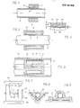
- the embodiment according to Fig.l has a rigidly acting outer, enclosing bearing part 3 and a variable diameter hollow guide rod 4. Via at least one radial channel 5 provided in the enclosing bearing part, air is formed under air pressure under cinem pressure of, for example, 5 atm (0.05 kp / mm 2 ) in the bearing gap 2, so that this has a constant width of, for example, 5 ⁇ in the circumferential direction of the bearing and both bearing parts 3 and 4 are centered with respect to one another.
- the surrounding bearing part 3 is widened by heating only for mounting on the rod.
- the exemplary embodiment according to FIG. 2 shows a surrounding bearing sleeve 8, the diameter of which can be reduced by the pressure of a medium in order to achieve a central clamping of the bearing.
- the medium i.e. Air or oil is introduced via an opening 9 into an annular chamber 10 enclosing the bearing sleeve 8, so that the bearing sleeve 8 is compressed and thus causes the clamping holder.
- the rod 4 can additionally be widened by internal overpressure in accordance with the aforementioned second clamping method.
- Fig. 3 shows a further embodiment in which the elongated guide part, i.e. the hollow cylindrical rod can behave rigidly according to Fig.2.
- the enclosed part 12 of the arrangement of the bearing is designed like a piston and slides on the inner surface 13 of the enclosing part 14.
- the piston-like enclosed part 12 carries an outer bearing sleeve 15, so that the precisely machined outer surface 16 together with the inner surface 13 forms the bearing surfaces.
- the bearing sleeve encloses an annular chamber 17 which is connected to an external pressure source via bores 18 in the piston-like part 12. For a clamping holder after the movement has stopped, the bearing sleeve 15 presses against the inner bearing surface 13 under the pressure of the medium in the annular chamber 17.
- the mutual approach of the bearing surfaces to the clamping bracket can, however, also take place in the embodiment according to FIG. 3 in various ways, for example by reducing the diameter of the bearing sleeve 15 under the pressure of the storage medium in the bearing gap and when this pressure is released due to its inherent elasticity, or also supported by an overpressure in the annular chamber 17, presses against the inner surface 13 of the bearing.
- This inner surface of the bearing can also move in the direction of the sleeve 15 when the bearing pressure decreases, if the surrounding part of the bearing is also not rigid.
- the wall of the deformable bearing part is preferably used in an advantageous embodiment of the invention or the deformable bearing parts as shown in Figure 4.
- This wall 21 has a multi-layer structure and has a greater proportion of layers with reinforcing fibers 22 running in the longitudinal direction or parallel to the axis parallel to the strength, compared to the transverse or circumferential reinforcing fibers 23 of the thinner layer 24.
- the latter fibers are glass fibers while the longitudinal fibers 22 of the thicker ones Layer 25 are carbon fibers, so that the modulus of elasticity of the thicker layer 25 is approximately five times.
- the so-called boiler formula it can be calculated that with a pressure of the storage medium of 5 atm, an average diameter of the bearing part 4 of 37.5 mm and a length of 500 mm, the change in length is not significantly greater than the change in diameter and is approximately 13 N. .
- the thickness ratio between the layers 24, 25 is, for example, 1: 4 with a total thickness of the wall 21 of 1.5 mm.
- the bedding material of the fibers is, for example, epoxy resin.
- FIG. 5 shows an application example of bearings 27, 28 according to the invention for the column guide 40 of a measuring machine.
- a measuring arm (not shown) is rigidly attached, which can be adjusted by the vertical displacement of the surrounding bearing parts 29, 30 on the measuring columns 31, 32 into different measuring positions and locked precisely there.
- Such a measuring machine is used, for example, in the case of a combination with a precisely mounted rotary table, to measure the roundness of objects. The roundness is to be measured in several precisely defined vertical positions of a probe attached to the end of the measuring arm.
- FIG. 6 and 7 show examples of slide guides which can be locked in a precise position by means of a bearing 35 or 36 according to the invention, in order to be able to exactly maintain predetermined adjustment positions.
- the torsionally stiff surface guidance according to FIG. 7 can be used advantageously, particularly with large weight loads.
- the bearing gap can be adjusted by pressure control in order to overcome manufacturing tolerances with regard to the geometric surface accuracy.
- the clamping force is also adjustable.
Landscapes
- Engineering & Computer Science (AREA)
- General Engineering & Computer Science (AREA)
- Mechanical Engineering (AREA)
- Sliding-Contact Bearings (AREA)
- Magnetic Bearings And Hydrostatic Bearings (AREA)
- Support Of The Bearing (AREA)
Applications Claiming Priority (2)
| Application Number | Priority Date | Filing Date | Title |
|---|---|---|---|
| CH4531/85 | 1985-10-21 | ||
| CH4531/85A CH668461A5 (de) | 1985-10-21 | 1985-10-21 | Lager, insbesondere fuer messeinrichtungen. |
Publications (3)
| Publication Number | Publication Date |
|---|---|
| EP0219768A2 true EP0219768A2 (fr) | 1987-04-29 |
| EP0219768A3 EP0219768A3 (en) | 1987-07-29 |
| EP0219768B1 EP0219768B1 (fr) | 1990-02-07 |
Family
ID=4277830
Family Applications (1)
| Application Number | Title | Priority Date | Filing Date |
|---|---|---|---|
| EP86113960A Expired - Lifetime EP0219768B1 (fr) | 1985-10-21 | 1986-10-08 | Palier |
Country Status (3)
| Country | Link |
|---|---|
| EP (1) | EP0219768B1 (fr) |
| CH (1) | CH668461A5 (fr) |
| DE (1) | DE3668956D1 (fr) |
Cited By (3)
| Publication number | Priority date | Publication date | Assignee | Title |
|---|---|---|---|---|
| EP1179392A3 (fr) * | 2000-05-19 | 2003-07-09 | A. Römheld GmbH & Co KG | Elément de fixation et support |
| EP1344615A3 (fr) * | 2002-03-15 | 2005-01-26 | Dienes Werke Für Maschinenteile Gmbh & Co Kg | Support de lame permettant le blocage sans jeu de la lame |
| CN110537932A (zh) * | 2019-07-30 | 2019-12-06 | 青岛市中心医院 | 可防止人体非检查部分受损的医学射线防护装置 |
Families Citing this family (2)
| Publication number | Priority date | Publication date | Assignee | Title |
|---|---|---|---|---|
| DE4112461C1 (en) * | 1991-04-12 | 1992-10-08 | Rud-Kettenfabrik Rieger & Dietz Gmbh U. Co, 7080 Aalen, De | Clamp or adjuster with hydraulically actuated diaphragm - which is formed by bottom of steel diaphragm body, while force transfer rod ends abut opposite body wall |
| DE10047240A1 (de) * | 2000-09-23 | 2002-05-29 | Wafios Ag | Einrichtung zur Führungsspielreduzierung und/oder Vorspannungsänderung bei Rundführungen |
Family Cites Families (3)
| Publication number | Priority date | Publication date | Assignee | Title |
|---|---|---|---|---|
| US3025072A (en) * | 1960-08-26 | 1962-03-13 | Specialties Inc | Clamping device |
| DE1894955U (de) * | 1963-09-27 | 1964-06-18 | Handelsgesellschaft Fuer Masch | Hydraulische klemmvorrichtung fuer den schlitten einer werkzeugmaschine od. dgl. |
| DE1952647U (de) * | 1966-10-06 | 1966-12-29 | Metron Waerme Und Messtechnik | Klemmelement mit hochdruckdicht eingebauter elastischer membrane fuer druckmittelbetaetigten druckkolben. |
-
1985
- 1985-10-21 CH CH4531/85A patent/CH668461A5/de not_active IP Right Cessation
-
1986
- 1986-10-08 DE DE8686113960T patent/DE3668956D1/de not_active Expired - Fee Related
- 1986-10-08 EP EP86113960A patent/EP0219768B1/fr not_active Expired - Lifetime
Cited By (3)
| Publication number | Priority date | Publication date | Assignee | Title |
|---|---|---|---|---|
| EP1179392A3 (fr) * | 2000-05-19 | 2003-07-09 | A. Römheld GmbH & Co KG | Elément de fixation et support |
| EP1344615A3 (fr) * | 2002-03-15 | 2005-01-26 | Dienes Werke Für Maschinenteile Gmbh & Co Kg | Support de lame permettant le blocage sans jeu de la lame |
| CN110537932A (zh) * | 2019-07-30 | 2019-12-06 | 青岛市中心医院 | 可防止人体非检查部分受损的医学射线防护装置 |
Also Published As
| Publication number | Publication date |
|---|---|
| CH668461A5 (de) | 1988-12-30 |
| EP0219768A3 (en) | 1987-07-29 |
| DE3668956D1 (de) | 1990-03-15 |
| EP0219768B1 (fr) | 1990-02-07 |
Similar Documents
| Publication | Publication Date | Title |
|---|---|---|
| DE3879675T2 (de) | Prozedur und gleitbare unterstützung für ein profilmepinstrument. | |
| DE3038112C2 (de) | Verfahren zum Einstellen der axialen Vorspannung einer zweireihigen Radialwälzlagerung für eine Welle und demgemäß montierte Lagerung | |
| EP0353376A1 (fr) | Outil de brunissage | |
| DE102015114212A1 (de) | Anordnung zum Einspannen eines rotierbaren Werkstücks | |
| EP2876409A1 (fr) | Unité de mesure destinée à mesurer des forages | |
| EP0087730A1 (fr) | Cylindre d'impression à axe longitudinal de forme variable | |
| DE102015115718A1 (de) | Messvorrichtung | |
| EP0517653B1 (fr) | Tête de mesure palpeur | |
| DE2530365B2 (de) | Einrichtung zur Durchmesserverstellung eines Zylinders | |
| DE2756183A1 (de) | Praezisions-vorschubtisch | |
| EP0219768A2 (fr) | Palier | |
| DE1577390C3 (de) | Einrichtung zum Hin- und Herbewegen der Schleifkörperhalterung einer Superfinish- oder Honmaschine | |
| DE3441426A1 (de) | Koordinatenmessmaschine | |
| DE9422389U1 (de) | Werkzeugschneiden-Verstelleinrichtung zum hochgenauen Bearbeiten von runden, unrunden und/oder nicht zylinderförmigen Innen- und/oder Außenkonturen | |
| WO2009060031A1 (fr) | Dispositif d'entraînement pour outils d'érosion | |
| DE3524438C2 (de) | Einrichtung zur Zylinderfehlerkompensation an einer Schleifmaschine | |
| DE3341507A1 (de) | Werkzeug zum honen von bohrungen bzw. wellen oder dgl. | |
| DE3447162A1 (de) | Vorrichtung zur lagerung von gewindespindeln | |
| DE890284C (de) | Gleit- oder Zapfenlageranordnung | |
| EP3133370B1 (fr) | Systeme de tuyere de mesure | |
| DE3405704C2 (fr) | ||
| DE3803470C2 (fr) | ||
| DE3835811C2 (fr) | ||
| DE69217667T2 (de) | Gleitschienenaufbau | |
| DE2102818C3 (de) | Breitstreckwalze |
Legal Events
| Date | Code | Title | Description |
|---|---|---|---|
| PUAI | Public reference made under article 153(3) epc to a published international application that has entered the european phase |
Free format text: ORIGINAL CODE: 0009012 |
|
| AK | Designated contracting states |
Kind code of ref document: A2 Designated state(s): DE FR GB IT NL SE |
|
| PUAL | Search report despatched |
Free format text: ORIGINAL CODE: 0009013 |
|
| AK | Designated contracting states |
Kind code of ref document: A3 Designated state(s): DE FR GB IT NL SE |
|
| 17P | Request for examination filed |
Effective date: 19870827 |
|
| 17Q | First examination report despatched |
Effective date: 19880811 |
|
| GRAA | (expected) grant |
Free format text: ORIGINAL CODE: 0009210 |
|
| AK | Designated contracting states |
Kind code of ref document: B1 Designated state(s): DE FR GB IT NL SE |
|
| PG25 | Lapsed in a contracting state [announced via postgrant information from national office to epo] |
Ref country code: IT Free format text: LAPSE BECAUSE OF FAILURE TO SUBMIT A TRANSLATION OF THE DESCRIPTION OR TO PAY THE FEE WITHIN THE PRE;WARNING: LAPSES OF ITALIAN PATENTS WITH EFFECTIVE DATE BEFORE 2007 MAY HAVE OCCURRED AT ANY TIME BEFORE 2007. THE CORRECT EFFECTIVE DATE MAY BE DIFFERENT FROM THE ONE RECORDED.SCRIBED TIME-LIMIT Effective date: 19900207 Ref country code: NL Effective date: 19900207 Ref country code: SE Effective date: 19900207 |
|
| REF | Corresponds to: |
Ref document number: 3668956 Country of ref document: DE Date of ref document: 19900315 |
|
| GBT | Gb: translation of ep patent filed (gb section 77(6)(a)/1977) | ||
| ET | Fr: translation filed | ||
| NLV1 | Nl: lapsed or annulled due to failure to fulfill the requirements of art. 29p and 29m of the patents act | ||
| PGFP | Annual fee paid to national office [announced via postgrant information from national office to epo] |
Ref country code: FR Payment date: 19900914 Year of fee payment: 5 |
|
| PGFP | Annual fee paid to national office [announced via postgrant information from national office to epo] |
Ref country code: DE Payment date: 19900917 Year of fee payment: 5 |
|
| PLBE | No opposition filed within time limit |
Free format text: ORIGINAL CODE: 0009261 |
|
| STAA | Information on the status of an ep patent application or granted ep patent |
Free format text: STATUS: NO OPPOSITION FILED WITHIN TIME LIMIT |
|
| 26N | No opposition filed | ||
| PGFP | Annual fee paid to national office [announced via postgrant information from national office to epo] |
Ref country code: GB Payment date: 19910808 Year of fee payment: 6 |
|
| PG25 | Lapsed in a contracting state [announced via postgrant information from national office to epo] |
Ref country code: FR Effective date: 19920630 |
|
| PG25 | Lapsed in a contracting state [announced via postgrant information from national office to epo] |
Ref country code: DE Effective date: 19920701 |
|
| REG | Reference to a national code |
Ref country code: FR Ref legal event code: ST |
|
| PG25 | Lapsed in a contracting state [announced via postgrant information from national office to epo] |
Ref country code: GB Effective date: 19921008 |
|
| GBPC | Gb: european patent ceased through non-payment of renewal fee |
Effective date: 19921008 |