EP0219938B1 - Dispositif de freinage - Google Patents
Dispositif de freinage Download PDFInfo
- Publication number
- EP0219938B1 EP0219938B1 EP86306351A EP86306351A EP0219938B1 EP 0219938 B1 EP0219938 B1 EP 0219938B1 EP 86306351 A EP86306351 A EP 86306351A EP 86306351 A EP86306351 A EP 86306351A EP 0219938 B1 EP0219938 B1 EP 0219938B1
- Authority
- EP
- European Patent Office
- Prior art keywords
- brake
- brake device
- disc
- housing portion
- shaft
- Prior art date
- Legal status (The legal status is an assumption and is not a legal conclusion. Google has not performed a legal analysis and makes no representation as to the accuracy of the status listed.)
- Expired
Links
- 230000000712 assembly Effects 0.000 claims description 11
- 238000000429 assembly Methods 0.000 claims description 11
- 239000012530 fluid Substances 0.000 claims description 9
- 238000000926 separation method Methods 0.000 claims description 3
- 238000005266 casting Methods 0.000 description 35
- 239000002775 capsule Substances 0.000 description 5
- 238000001816 cooling Methods 0.000 description 2
- 229910052751 metal Inorganic materials 0.000 description 2
- 239000002184 metal Substances 0.000 description 2
- 230000000717 retained effect Effects 0.000 description 2
- 229910000639 Spring steel Inorganic materials 0.000 description 1
- 239000004411 aluminium Substances 0.000 description 1
- 229910052782 aluminium Inorganic materials 0.000 description 1
- XAGFODPZIPBFFR-UHFFFAOYSA-N aluminium Chemical compound [Al] XAGFODPZIPBFFR-UHFFFAOYSA-N 0.000 description 1
- 239000004744 fabric Substances 0.000 description 1
- 238000009413 insulation Methods 0.000 description 1
- 210000002445 nipple Anatomy 0.000 description 1
- 229920003023 plastic Polymers 0.000 description 1
- 239000004033 plastic Substances 0.000 description 1
- 239000007787 solid Substances 0.000 description 1
Images


Classifications
-
- F—MECHANICAL ENGINEERING; LIGHTING; HEATING; WEAPONS; BLASTING
- F16—ENGINEERING ELEMENTS AND UNITS; GENERAL MEASURES FOR PRODUCING AND MAINTAINING EFFECTIVE FUNCTIONING OF MACHINES OR INSTALLATIONS; THERMAL INSULATION IN GENERAL
- F16D—COUPLINGS FOR TRANSMITTING ROTATION; CLUTCHES; BRAKES
- F16D65/00—Parts or details
- F16D65/78—Features relating to cooling
- F16D65/84—Features relating to cooling for disc brakes
- F16D65/847—Features relating to cooling for disc brakes with open cooling system, e.g. cooled by air
-
- F—MECHANICAL ENGINEERING; LIGHTING; HEATING; WEAPONS; BLASTING
- F16—ENGINEERING ELEMENTS AND UNITS; GENERAL MEASURES FOR PRODUCING AND MAINTAINING EFFECTIVE FUNCTIONING OF MACHINES OR INSTALLATIONS; THERMAL INSULATION IN GENERAL
- F16D—COUPLINGS FOR TRANSMITTING ROTATION; CLUTCHES; BRAKES
- F16D55/00—Brakes with substantially-radial braking surfaces pressed together in axial direction, e.g. disc brakes
- F16D55/24—Brakes with substantially-radial braking surfaces pressed together in axial direction, e.g. disc brakes with a plurality of axially-movable discs, lamellae, or pads, pressed from one side towards an axially-located member
- F16D55/26—Brakes with substantially-radial braking surfaces pressed together in axial direction, e.g. disc brakes with a plurality of axially-movable discs, lamellae, or pads, pressed from one side towards an axially-located member without self-tightening action
- F16D55/28—Brakes with only one rotating disc
- F16D55/32—Brakes with only one rotating disc actuated by a fluid-pressure device arranged in or on the brake
-
- F—MECHANICAL ENGINEERING; LIGHTING; HEATING; WEAPONS; BLASTING
- F16—ENGINEERING ELEMENTS AND UNITS; GENERAL MEASURES FOR PRODUCING AND MAINTAINING EFFECTIVE FUNCTIONING OF MACHINES OR INSTALLATIONS; THERMAL INSULATION IN GENERAL
- F16D—COUPLINGS FOR TRANSMITTING ROTATION; CLUTCHES; BRAKES
- F16D65/00—Parts or details
- F16D65/14—Actuating mechanisms for brakes; Means for initiating operation at a predetermined position
Definitions
- the invention relates to a brake device for braking a shaft, the brake device comprising a brake disc carried by the shaft, and brake assemblies each including a brake element which is selectively movable into frictional engagement with the brake disc, the brake assemblies being carried by a support member which can be pivoted between an operative position in which the brake elements of the brake assemblies can engage the brake disc and a servicing position in which the brake assemblies are spaced from the brake disc.
- a winch spool with a disc brake system in which a caliper mounts selectively operable brake assemblies.
- the caliper can be pivoted from an operative position to a servicing position about an axis which extends parallel to the brake disc axis.
- a vehicle brake in which a support member carrying a brake pad can be pivoted about an axis transverse to the axis of a brake disc, but the brake pad is fired, and not part of brake assembly by which it can be selectively moved against the brake disc.
- a brake device of the kind described is characterised in that the support member comprises a front portion of a housing in which the brake disc is contained, the front portion being pivoted on a fixed rear portion of the housing, through which the shaft protrudes, about an axis transverse to the brake disc axis.
- the front housing portion can thus be pivoted for example downwardly on about a generally horizontal axis, for example an axis below and perpendicular to a generally horizontal shaft axis, to expose for servicing the brake pads and the actuators which drive them.
- the front housing portion can be pivotable for movement relative to the rear portion of the housing through an appropriate angle, say 90° or 180° and the pivot arrangement can be such as to facilitate separation of the support from the device.
- the front housing portion can be square or rectangular with a hinge connection along one side and fastening means at the other, in the form for example of a fastening clamp or bolt, which may be associated with a locating means, at each corner.
- the brake disc is preferably backed by a further braking pad or pads, which may be passive or movable to apply a positive braking force, and which are preferably disposed directly opposite the first- mentioned braking pads.
- the invention can provide that the brake disc is readily removable from its shaft for example by being slideably received thereon by way of co-operating interior and exterior splines.
- the housing is preferably apertured to allow a cooling air flow therethrough, and may have side walls with wire mesh guard screen or a pressed metal screen formed with lips at its ends by which it can be slidingly received on ridges formed on corner pillars of the housing.
- the air flow is preferably induced by an impeller means and this can conveniently be constituted by the brake disc itself.
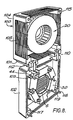
- the brake device 1 of Figs. 1 - 6 comprises a housing having front and rear portions 2 and 4 formed as aluminium casting.
- the rear casting 4 has the form of a generally square open-topped box, of which the apertured base wall is connected in use to an apparatus of which a rotary shaft is to be braked.
- the sides are constituted by corner posts joined by louvres spaced so as not to unduly obstruct airflow.
- the front casting 2 is also generally of the form of a square open-topped box, of which the sides are solid, whilst the base wall, which forms the front of the housing has an inwardly protruding sleeve portion 6 across which extend guard ribs 7, again shaped so as not to unduly obstruct airflow.
- the lower corner posts of the rear casting 4 have forwardly protruding lugs 10 received in slots in the corresponding corner posts 11 of the casting 2 through which extend pivot bolts 12 on which the front casting can pivot through about 90° between the closed position of Fig. 1 and the open position of Fig. 2.
- the bolts 12 are preferably readily withdrawable to allow separation of the two castings.
- the upper corner posts 15 of the rear casting 4 have recesses for receiving fixing bolts 16 extending through holes in the corresponding corner posts 17 of the front casting 2. Locating cones 19 on the corner posts 15 are receivable in the holes in the corner posts 17 to assist alignment of the two housing portions as the casting 4 is pivoted upwardly to the closed position in which they are secured together by turning the ends of the bolts 16 accessible from the front of the housing.
- a brake disc 20 within the housing is slidably received on the shaft to be braked.
- the brake disc as shown in Figs. 3 and 4, comprises spaced front and rear annular walls 22 and 24 having vanes extending inwardly between them to induce a cooling airflow through the brake device.
- the central aperture of the front wall 22 matches that of the sleeve 6 formed in the front housing casting 2, to ensure good air flow.
- a hub 26 projecting rearwardly from the inner wall 24 is internally splined at 27 for co-operation with splines at an end of the shaft to be braked.
- the exposed side of the wall 22 can be frictionally engaged by brake pads 30 mounted by way of actuators 31 in the front casting 2, on operation of the actuators.
- each brake pad mounted by the front casting 2 is directly opposed axially of the shaft and brake disc 20 by a brake pad mounted on the rear casting 4.
- the rear brake pads could be movable by actuators, like the pads 30, they are normally fixed in position in the casting 4.
- Each of the brake pads 30 forms, together with the fluid pressure operated actuator 31, a part of a braking assembly which may correspond to the brake pad actuator assembly described in GB 2 100 184 A.
- the assembly can comprise the friction puck or brake pad 30, which is preferably non-circular, for example, rectangular, in cross-section, to provide a larger engagement area than a circular pad, and an actuator 31 of circular cross-section comprising an elastomeric capsule 32, which may be fabric reinforced and which is operated by pressure fluid (oil or compressed air) fed into the capsule by way of a nipple 34.
- the pressure fluid is supplied to the device 1 by a tube 35 and distribute to the various actuators by a pipe 36 and a distribution manifold clamped inside the casting 2. Between the actuator capsule and the brake pad there is provided an insulation pad 37.
- Each actuator 31 is located on the casting 2 by a part-circular integrally formed actuator location web 40 and by an opposed arcuate exterior surface portion 41 of the sleeve 6. Concentrically within the web 40 and the surface portion 41, are provided likewise integrally formed part-circular webs 42 which afford backing support for the actuator capsule 32.
- brake pad guides 44 comprising axially extending walls, of which the side edges are received in grooves formed in the brake pads 30. The brake pads are thus guided for strictly axial movement in depencence on the fluid pressure applied to the capsule 32.
- the brake device 100 again has a housing comprising hingedly connected front and rear castings 102 and 104 functioning similarly to the castings 2 and 4 and of generally similar shape.
- the sides of the rear casting 104 however have major cut-out portions between corner posts 115 which have channels for slidably receiving welded wire guards 105, which can be readily removed when the housing is open for improved access to the rear casting interior.
- the guards are retained by further channels in the edges of the sides of the front casting.
- the rear casting 104 has an extension 101 on which the front casting 102 is pivoted.
- the front portion of the extension 101 is formed with upright slots within which are received lugs 110 extending from the front casting.
- Bolts 112 secured by nuts operate as hinge pins and retain the castings together.
- the slots and lugs are so arranged that the front casting can pivot downwardly from the fixed rear casting through approximately 180°.
- the hinge pins 112 again can be readily removed, so that the two castings can be completely separated.
- the castings 102 and 104 are releasably secured together by clamping bolts 116 received in holes extending through the upper front casing corner posts 117, and through locating cones 119 receivable in recesses in the rear casting corner posts 115.
- the front casting 102 mounts six assemblies, each comprising a braking pad 30 and an actuator 31, in the same way as the casting 2.
- replaceable slide inserts 103 in the form of spring steel strips or of lenghts of an extended plastics strip of suitable cross-section, are provided between each edge of the guide and the associated brake pad.
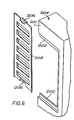
- the side walls 201 of the rear housing portion 204 are formed with substantially rectangular cut-out portions, edged with integrally cast ridges 202, for reception of an apertured grille 205.
- the grille 205 is a rectangular metal pressing formed at around the middle of its shorter edges with flap portions or lips 206 turned out at right angles to the plane of the grille and then outwardly parallel to this plane.
- the ridges 202 are slidably received between this lip 206 and the adjacent edges of the grille.
- the ridges 202 are readily integrally cast and the grille 205 can be readily replaced after removal for access to the housing interior.
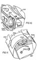
- a selection manifold 210 for control of fluid pressure to actuators 220 mounted on the front housing portion 212 of the third brake device, which is hingedly connected to the housing portion 204 by pivot bolts 214.
- Pressure fluid is supplied to each manifold 210 by a fluid pressure line (not shown) for distribution being controlled by longitudinal movement of valve spools 216 received in bores through the manifold 210. An end of each spool 216 is accessible at the housing exterior, as shown.
- Each of the actuators 220 is arranged to apply a brake or friction pad 30 to the brake disc 20, and is located in the front housing portion 202 by integrally cast projections 221.
- the brake pad 30 is received on posts 222 in apertures in the pad and forms part of an assembly comprising also a guide ring 224, around and slidable on the projections 221, on which the pad is retained by spring clips 225.
- Each clip 225 has a generally rectangular base part by which it is held in place between three upstanding locating pins 22, and an extension part curved to provide a rounded surface engaging against a side of the brake pad 30.
Landscapes
- Engineering & Computer Science (AREA)
- General Engineering & Computer Science (AREA)
- Mechanical Engineering (AREA)
- Braking Arrangements (AREA)
Claims (12)
Applications Claiming Priority (2)
| Application Number | Priority Date | Filing Date | Title |
|---|---|---|---|
| GB858521630A GB8521630D0 (en) | 1985-08-30 | 1985-08-30 | Brake device |
| GB8521630 | 1985-08-30 |
Publications (2)
| Publication Number | Publication Date |
|---|---|
| EP0219938A1 EP0219938A1 (fr) | 1987-04-29 |
| EP0219938B1 true EP0219938B1 (fr) | 1990-01-31 |
Family
ID=10584497
Family Applications (1)
| Application Number | Title | Priority Date | Filing Date |
|---|---|---|---|
| EP86306351A Expired EP0219938B1 (fr) | 1985-08-30 | 1986-08-18 | Dispositif de freinage |
Country Status (5)
| Country | Link |
|---|---|
| US (1) | US4782922A (fr) |
| EP (1) | EP0219938B1 (fr) |
| JP (2) | JPS6293528A (fr) |
| DE (1) | DE3668674D1 (fr) |
| GB (1) | GB8521630D0 (fr) |
Families Citing this family (9)
| Publication number | Priority date | Publication date | Assignee | Title |
|---|---|---|---|---|
| GB8717169D0 (en) * | 1987-07-21 | 1987-08-26 | Ti Interlock Ltd | Pneumatic control system |
| DE4018987A1 (de) * | 1990-06-13 | 1991-12-19 | Knorr Bremse Ag | Lamellenscheibenbremse fuer schienenfahrzeuge |
| US5248013A (en) * | 1992-02-13 | 1993-09-28 | The B. F. Goodrich Company | Heatshield installation for aircraft brake |
| GB9203216D0 (en) * | 1992-02-14 | 1992-04-01 | Ti Interlock Ltd | Fluid operated brake device |
| FR2697218B1 (fr) * | 1992-10-26 | 1994-12-16 | Alsthom Gec | Système de freinage pour véhicule ferroviaire utilisant des matériaux à base de carbone. |
| GB9321079D0 (en) * | 1993-10-13 | 1993-12-01 | Ti Interlock Ltd | Brake device |
| JP5037459B2 (ja) * | 2008-08-29 | 2012-09-26 | 東芝テック株式会社 | 商品販売データ処理装置およびその制御プログラム |
| US9739326B2 (en) * | 2013-10-22 | 2017-08-22 | Bell Helicopter Textron Inc. | Rotor brake with integrated impeller |
| TWD174067S (zh) * | 2015-07-07 | 2016-03-01 | 溫芫鋐 | 來令片散熱結構之部分 |
Family Cites Families (25)
| Publication number | Priority date | Publication date | Assignee | Title |
|---|---|---|---|---|
| FR960072A (fr) * | 1947-06-14 | 1950-04-12 | ||
| FR1090611A (fr) * | 1953-09-29 | 1955-04-01 | Rech Etudes Production Sarl | Frein à disques pour roues, en particulier de voitures automobiles |
| US3310698A (en) * | 1964-02-11 | 1967-03-21 | Imc Magnetics Corp | Machine frame for an electric motor |
| US3323625A (en) * | 1965-07-28 | 1967-06-06 | Thermo King Corp | Detachable power assembly |
| DE1575789A1 (de) * | 1967-03-03 | 1970-08-20 | Bergische Stahlindustrie | Teilbelagscheibenbremse insbesondere fuer Kraftfahrzeuge |
| US3661235A (en) * | 1969-03-22 | 1972-05-09 | Girling Ltd | Brake disc and hub combination |
| US3610380A (en) * | 1969-08-26 | 1971-10-05 | Montalvo And Co Inc | Coupling with pivotally mounted motors and friction elements |
| US3602328A (en) * | 1969-10-21 | 1971-08-31 | Dayton Steel Foundry Co | Caliper type disc brake with remarkable friction pads |
| US3637053A (en) * | 1970-03-30 | 1972-01-25 | Disco Ind Inc | Disc brake apparatus |
| DE2326992A1 (de) * | 1970-04-24 | 1973-12-13 | Klaue Hermann Dr-Ing | Mit einer scheibenbremse ausgeruestetes bremsrad, insbesondere fuer kraftfahrzeuge |
| US3899054A (en) * | 1974-02-08 | 1975-08-12 | Abex Corp | Disc brakes with cooling rods |
| GB1450492A (en) * | 1974-05-01 | 1976-09-22 | Texas Techn Enterprises | Winch spool with disc brake system |
| US3955650A (en) * | 1975-01-31 | 1976-05-11 | Ellis Max H | Aerodynamically ventilated disc brake |
| FR2398930B2 (fr) * | 1977-05-25 | 1982-12-03 | Girling Ltd | Frein a disque et a pince coulissante |
| US4171038A (en) * | 1977-11-09 | 1979-10-16 | G. M. Sommer Company, Inc. | Clutch unit |
| US4245722A (en) * | 1978-07-28 | 1981-01-20 | Wabco Fahrzeugbremsen Gmbh | Vehicle disk brake with improved means for changing brake pads |
| US4235315A (en) * | 1978-07-28 | 1980-11-25 | Wabco Fahrzeugbremsen Gmbh | Full disk brake |
| DE2839791A1 (de) * | 1978-09-13 | 1980-03-27 | Kloeckner Humboldt Deutz Ag | Teilbelagscheibenbremse, insbesondere fuer land- und/oder bauwirtschaftlich nutzbare kraftfahrzeuge |
| US4566351A (en) * | 1979-04-09 | 1986-01-28 | Rockwell International Corporation | Gear housing device for preventing oil leakage |
| FR2503816A1 (fr) * | 1981-04-14 | 1982-10-15 | Dba | Patin de frein a disque et frein a disque equipe d'un tel patin |
| US4418807A (en) * | 1981-05-11 | 1983-12-06 | Horton Industries, Inc. | Friction interface unit for a clutch and a brake |
| GB2100814B (en) * | 1981-06-19 | 1984-12-19 | Ti Interlock Ltd | Spot brake |
| JPS58109739A (ja) * | 1981-12-22 | 1983-06-30 | Akebono Brake Ind Co Ltd | ピンタイプデイスクブレ−キ |
| SE8303053L (sv) * | 1983-05-31 | 1984-12-01 | Kelva Ab | Skivbroms |
| US4666025A (en) * | 1985-05-02 | 1987-05-19 | Magnetic Power Systems, Inc. | Retraction means for friction members in friction coupling brakes and clutches |
-
1985
- 1985-08-30 GB GB858521630A patent/GB8521630D0/en active Pending
-
1986
- 1986-08-18 EP EP86306351A patent/EP0219938B1/fr not_active Expired
- 1986-08-18 DE DE8686306351T patent/DE3668674D1/de not_active Expired - Fee Related
- 1986-08-26 US US06/900,554 patent/US4782922A/en not_active Expired - Fee Related
- 1986-08-29 JP JP61203533A patent/JPS6293528A/ja active Pending
-
1990
- 1990-12-25 JP JP1990401761U patent/JPH0544590Y2/ja not_active Expired - Lifetime
Also Published As
| Publication number | Publication date |
|---|---|
| DE3668674D1 (de) | 1990-03-08 |
| EP0219938A1 (fr) | 1987-04-29 |
| JPH0544590Y2 (fr) | 1993-11-12 |
| JPS6293528A (ja) | 1987-04-30 |
| JPH03127839U (fr) | 1991-12-24 |
| GB8521630D0 (en) | 1985-10-02 |
| US4782922A (en) | 1988-11-08 |
Similar Documents
| Publication | Publication Date | Title |
|---|---|---|
| EP0219938B1 (fr) | Dispositif de freinage | |
| CA1112189A (fr) | Frein a disque | |
| EP0851139B1 (fr) | Frein à disque | |
| CA1197479A (fr) | Dispositif de freinage | |
| JP2593271B2 (ja) | 湿式ディスクブレーキ | |
| US6345701B1 (en) | Anchor bracket and brake shoe assembly for use in a disc brake assembly | |
| RU2003101401A (ru) | Дисковый тормоз с жесткозакрепленным суппортом, имеющий малый коэффициент взаимного перекрытия | |
| US3942612A (en) | Friction pad mounting means for a disc brake caliper | |
| US4666025A (en) | Retraction means for friction members in friction coupling brakes and clutches | |
| US4111285A (en) | Slidable caliper and pivotal mounting means therefor | |
| US4771870A (en) | Brake shoe assembly | |
| SE509044C2 (sv) | Anordning vid broms | |
| EP3019764B1 (fr) | Dispositif et procédé de retenue de plaquette de frein | |
| JPH10318299A (ja) | 交換可能な摩擦用パッド付きモジュラー・ブレーキ | |
| CA1222959A (fr) | Etrier pour frein a disque, et sa fabrication | |
| US4342381A (en) | Disc brake | |
| JPH05106669A (ja) | ブレーキブロツク | |
| USRE24996E (en) | Disc brakes | |
| US4360083A (en) | Disc brake protective cover plate | |
| US4129200A (en) | Disc brake and mounting therefor | |
| JPH0261656B2 (fr) | ||
| JPS6040905Y2 (ja) | デイスクブレ−キの引きずり防止装置 | |
| US3258089A (en) | Spot type disk brake | |
| US2946408A (en) | Disc brake | |
| US2909246A (en) | Disc brakes |
Legal Events
| Date | Code | Title | Description |
|---|---|---|---|
| PUAI | Public reference made under article 153(3) epc to a published international application that has entered the european phase |
Free format text: ORIGINAL CODE: 0009012 |
|
| AK | Designated contracting states |
Kind code of ref document: A1 Designated state(s): DE GB IT |
|
| 17P | Request for examination filed |
Effective date: 19870616 |
|
| 17Q | First examination report despatched |
Effective date: 19880429 |
|
| ITF | It: translation for a ep patent filed | ||
| GRAA | (expected) grant |
Free format text: ORIGINAL CODE: 0009210 |
|
| AK | Designated contracting states |
Kind code of ref document: B1 Designated state(s): DE GB IT |
|
| REF | Corresponds to: |
Ref document number: 3668674 Country of ref document: DE Date of ref document: 19900308 |
|
| PLBE | No opposition filed within time limit |
Free format text: ORIGINAL CODE: 0009261 |
|
| STAA | Information on the status of an ep patent application or granted ep patent |
Free format text: STATUS: NO OPPOSITION FILED WITHIN TIME LIMIT |
|
| 26N | No opposition filed | ||
| ITTA | It: last paid annual fee | ||
| PGFP | Annual fee paid to national office [announced via postgrant information from national office to epo] |
Ref country code: GB Payment date: 19960809 Year of fee payment: 11 |
|
| PGFP | Annual fee paid to national office [announced via postgrant information from national office to epo] |
Ref country code: DE Payment date: 19960823 Year of fee payment: 11 |
|
| PG25 | Lapsed in a contracting state [announced via postgrant information from national office to epo] |
Ref country code: GB Free format text: LAPSE BECAUSE OF NON-PAYMENT OF DUE FEES Effective date: 19970818 |
|
| GBPC | Gb: european patent ceased through non-payment of renewal fee |
Effective date: 19970818 |
|
| PG25 | Lapsed in a contracting state [announced via postgrant information from national office to epo] |
Ref country code: DE Free format text: LAPSE BECAUSE OF NON-PAYMENT OF DUE FEES Effective date: 19980501 |
|
| PG25 | Lapsed in a contracting state [announced via postgrant information from national office to epo] |
Ref country code: IT Free format text: LAPSE BECAUSE OF NON-PAYMENT OF DUE FEES;WARNING: LAPSES OF ITALIAN PATENTS WITH EFFECTIVE DATE BEFORE 2007 MAY HAVE OCCURRED AT ANY TIME BEFORE 2007. THE CORRECT EFFECTIVE DATE MAY BE DIFFERENT FROM THE ONE RECORDED. Effective date: 20050818 |