EP0219955A1 - Abfallverbrennungssystem - Google Patents
Abfallverbrennungssystem Download PDFInfo
- Publication number
- EP0219955A1 EP0219955A1 EP86306831A EP86306831A EP0219955A1 EP 0219955 A1 EP0219955 A1 EP 0219955A1 EP 86306831 A EP86306831 A EP 86306831A EP 86306831 A EP86306831 A EP 86306831A EP 0219955 A1 EP0219955 A1 EP 0219955A1
- Authority
- EP
- European Patent Office
- Prior art keywords
- heat exchanger
- chamber
- aspirator
- combustion chamber
- tubes
- Prior art date
- Legal status (The legal status is an assumption and is not a legal conclusion. Google has not performed a legal analysis and makes no representation as to the accuracy of the status listed.)
- Withdrawn
Links
- 238000002485 combustion reaction Methods 0.000 claims abstract description 49
- 230000000694 effects Effects 0.000 claims abstract description 3
- 239000002184 metal Substances 0.000 claims 1
- 238000010276 construction Methods 0.000 abstract description 5
- 239000007789 gas Substances 0.000 description 5
- 238000000034 method Methods 0.000 description 4
- 230000008878 coupling Effects 0.000 description 3
- 238000010168 coupling process Methods 0.000 description 3
- 238000005859 coupling reaction Methods 0.000 description 3
- 239000000203 mixture Substances 0.000 description 3
- 229910001220 stainless steel Inorganic materials 0.000 description 2
- 239000010935 stainless steel Substances 0.000 description 2
- MFRCZYUUKMFJQJ-UHFFFAOYSA-N 1,4-dioxane-2,5-dione;1,3-dioxan-2-one Chemical compound O=C1OCCCO1.O=C1COC(=O)CO1 MFRCZYUUKMFJQJ-UHFFFAOYSA-N 0.000 description 1
- 238000003915 air pollution Methods 0.000 description 1
- 238000010586 diagram Methods 0.000 description 1
- 238000001035 drying Methods 0.000 description 1
- 235000019256 formaldehyde Nutrition 0.000 description 1
- 239000000446 fuel Substances 0.000 description 1
- 239000002737 fuel gas Substances 0.000 description 1
- 238000009413 insulation Methods 0.000 description 1
- 238000012986 modification Methods 0.000 description 1
- 230000004048 modification Effects 0.000 description 1
- 230000001473 noxious effect Effects 0.000 description 1
- 230000003647 oxidation Effects 0.000 description 1
- 238000007254 oxidation reaction Methods 0.000 description 1
- XLYOFNOQVPJJNP-UHFFFAOYSA-N water Substances O XLYOFNOQVPJJNP-UHFFFAOYSA-N 0.000 description 1
Images
Classifications
-
- F—MECHANICAL ENGINEERING; LIGHTING; HEATING; WEAPONS; BLASTING
- F23—COMBUSTION APPARATUS; COMBUSTION PROCESSES
- F23G—CREMATION FURNACES; CONSUMING WASTE PRODUCTS BY COMBUSTION
- F23G7/00—Incinerators or other apparatus for consuming industrial waste, e.g. chemicals
- F23G7/06—Incinerators or other apparatus for consuming industrial waste, e.g. chemicals of waste gases or noxious gases, e.g. exhaust gases
-
- F—MECHANICAL ENGINEERING; LIGHTING; HEATING; WEAPONS; BLASTING
- F23—COMBUSTION APPARATUS; COMBUSTION PROCESSES
- F23G—CREMATION FURNACES; CONSUMING WASTE PRODUCTS BY COMBUSTION
- F23G7/00—Incinerators or other apparatus for consuming industrial waste, e.g. chemicals
- F23G7/06—Incinerators or other apparatus for consuming industrial waste, e.g. chemicals of waste gases or noxious gases, e.g. exhaust gases
- F23G7/061—Incinerators or other apparatus for consuming industrial waste, e.g. chemicals of waste gases or noxious gases, e.g. exhaust gases with supplementary heating
- F23G7/065—Incinerators or other apparatus for consuming industrial waste, e.g. chemicals of waste gases or noxious gases, e.g. exhaust gases with supplementary heating using gaseous or liquid fuel
- F23G7/066—Incinerators or other apparatus for consuming industrial waste, e.g. chemicals of waste gases or noxious gases, e.g. exhaust gases with supplementary heating using gaseous or liquid fuel preheating the waste gas by the heat of the combustion, e.g. recuperation type incinerator
Definitions
- This invention relates to heat exchanger systems, and more particularly to heat exchanger arrangements that are useful in systems for incinerating organic vapors and the like.
- the organic vapors are subject to combustion and discharged at a temperature on the order of 1400°F. and the hot incineration discharge is desirably used to preheat the input dilute vapor mixture, in a heat exchanger, so that less fuel is required to operate the process.
- the pressure of the vapor mixture supplied through the heat exchanger is usually at a higher pressure than the combustion chamber exhaust as it is typically not desirable to locate the fan or other pressurizing device in the hottest zone due to factors such as added expense and inefficiencies.
- a heat exchanger - combustion chamber construction that includes structure defining a combustion chamber and structure defining a neat exchanger chamber. Disposed in the heat exchanger chamber is an array of inlet tubes, the outlets of which discharge into the combustion chamber. Combustion products discharged from the combustion chamber are flowed over the inlet tubes in heat exchange relation.
- An array of aspirator sleeves of larger inner dimension than the outer dimension of the inlet tubes is secured to divider structure between the heat exchanger chamber and the combustion chamber, each aspirator sleeve receiving the outlet end of a heat exchanger tube while permitting lontigudinal movement of the heat exchanger tube within the sleeve (due to thermal expansion, for example). Inlet vapor flow through the tubes produces a reduced pressure effect in the sleeves to a value below the pressure of the exhaust gas in the heat exchanger chamber so that there is recycle flow of a small fraction of the combustion products through the aspirator sleeves back into the combustion chamber.
- the outlet end of the aspirator sleeve extends at least one outlet diameter beyond the end of the tube received within the sleeve.
- the supply tube configuration may be varied depending on the application and in particular embodiments may be of either straight sided or have a reduced discharge end dimension.
- the inlet end of each aspirator sleeve is secured to the heat exchanger-combustion chamber divider wall by a rolled seal, the sleeve does not extend more than four diameters from the discharge end of the heat exchanger tube, and each heat exchanger tube is similarly secured to the inlet wall of the heat exchanger chamber wall by a rolled seal.
- Baffles in the heat exchanger chamber provide a tortutous path for the flow of combustion products through the heat exchanger chamber, and a parallel bypass channel is provided together with damper structure to allow a portion of the combustion products to bypass the heat exchanger chamber as desired.
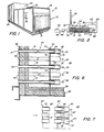
- the incineration system shown in Fig. 1 includes a housing 10 that has inlet flange 12 in which the inlet ends 14 of an array of heat exchanger tubes 16 are exposed; and outlet flange 18; a combustion chamber section 20 with fuel gas inlet 22; and a heat exchanger chamber section 24 in which tubes 16 are disposed, together with control 26 for operating damper 28 that controls or directs exhaust gas flow either through a heat exchanger chamber 24 or bypass duct 30 (Fig. 2).
- Housing 10 has a length of about twenty-seven feet, a height of about ten feet at its combustion chamber end, a height of about seven feet at its inlet end, and a width of about seven and one-half feet.
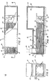
- vapors from a web-drying process diagrammatically indicated at 40 are transported through line 42 and blower 44 to coupling 46 which is secured to inlet flange 12 of the incineration system.
- the vapor mixture flows through heat exchanger tubes 16 into combustion chamber 48 in which burner 50 is mounted.
- the gases exhausted from combustion chamber 48 flow along path 52 for return through the heat exchanger chamber 24 over the tubes 16 as directed by baffles 54 for discharge through coupling 56 secured to outlet flange 18 and exhaust stack 58 to the atmosphere.
- the system includes an array of one hundred fifty eight stainless steel tubes (of sixteen gauge wall and two inch outer diameter) that are eighteen feet long with their inlet ends 60 rolled into inlet heat exchanger wall 62 and sealed to that wall, and the tubes extending through baffle plates 54 and through heat exchanger outlet chamber wall 64, each tube 16 extending about two inches beyond wall 64.
- Secured to chamber wall 64 is an outlet or aspirator sleeve 70 that has an inlet end 72 rolled into and sealed to wall 64 as indicated in Fig. 6.
- Each aspiration sleeve 70 is a stainless steel sixteen gauge wall two and one quarter inch outer diameter and a length of six inches.
- Wall 64 separates a heat exchanger chamber 24 from the combustion chamber 48 in which burner 50 (Maxon Combustifume Burner LV Model) is disposed.
- Fire wall structure 80 and thermal insulation 82 line the heat exchanger chamber 24 and the combustion chamber 48; and divider wall 84 separates heat exchanger chamber 24 from bypass duct 30.
- vapors from process 40 are flowed under pressure by blower 44 into tubes 16 at variable flow rates of up to about 12,000 scfm to produce discharge velocities of about 8000 feet per minute (based on hot gas) at the entry to combustion chamber 48.
- the vapors are subjected to an incineration process in chamber 48 with the combustion products being discharged from combustion chamber 48 at a pressure of less than about one inch of water and a temperature of about 1,400°F, for flow through the heat exchanger chamber 24 as directed by baffles 54 to the outlet coupling 56 and stack 58.
- the high velocity discharge of the vapors from tubes 16 creates regions of reduced pressure between the inner surface 92 of each aspiration sleeve 76 and the outer surface of tube 16.
- the slip fit between tube 16 and aspiration sleeve 70 provides a path for recycle flow of a small fraction of combustion products from the heat exchanger chamber back into the combustion chanber 48, thus providing an effective dynamic seal that blocks short circuit flow of the input gas stream and incorporates thermal expansion compensation for the heat exchanger tubes 16.
- tubes 16' have ends 96 of reduced diameter to provide velocity enhancement of discharged vapor in jets 90' to provide a similar zone of reduced pressure between each aspirator sleeve tube 70' and the heat exchanger tube 16' which draws product from the heat exchanger chamber 24' through the aspirator sleeves 70' into the combustion chamber 48' for reincineration.
Landscapes
- Engineering & Computer Science (AREA)
- Environmental & Geological Engineering (AREA)
- Mechanical Engineering (AREA)
- General Engineering & Computer Science (AREA)
- Heat-Exchange Devices With Radiators And Conduit Assemblies (AREA)
- Incineration Of Waste (AREA)
Applications Claiming Priority (2)
| Application Number | Priority Date | Filing Date | Title |
|---|---|---|---|
| US06/776,008 US4615674A (en) | 1985-09-13 | 1985-09-13 | Incinerator system |
| US776008 | 1985-09-13 |
Publications (1)
| Publication Number | Publication Date |
|---|---|
| EP0219955A1 true EP0219955A1 (de) | 1987-04-29 |
Family
ID=25106195
Family Applications (1)
| Application Number | Title | Priority Date | Filing Date |
|---|---|---|---|
| EP86306831A Withdrawn EP0219955A1 (de) | 1985-09-13 | 1986-09-03 | Abfallverbrennungssystem |
Country Status (6)
| Country | Link |
|---|---|
| US (1) | US4615674A (de) |
| EP (1) | EP0219955A1 (de) |
| JP (1) | JPH068687B2 (de) |
| KR (1) | KR950007391B1 (de) |
| CN (1) | CN86106035A (de) |
| CA (1) | CA1259523A (de) |
Families Citing this family (4)
| Publication number | Priority date | Publication date | Assignee | Title |
|---|---|---|---|---|
| AU2011213886B2 (en) * | 2010-08-26 | 2014-06-19 | First Water Ramsbury Limited | Wound dressing |
| CN102767836A (zh) * | 2012-08-01 | 2012-11-07 | 安徽理工大学 | 一种矿井风排瓦斯燃烧热能利用装置 |
| US9927183B2 (en) * | 2015-03-18 | 2018-03-27 | Mahle International Gmbh | Exhaust gas heat transfer device |
| CN106705077B (zh) * | 2017-01-04 | 2018-10-23 | 佛山安洁保节能设备有限公司 | 废气焚烧装置 |
Citations (5)
| Publication number | Priority date | Publication date | Assignee | Title |
|---|---|---|---|---|
| US1980077A (en) * | 1933-12-23 | 1934-11-06 | Surface Combustion Corp | Recuperator |
| DE1106020B (de) * | 1957-10-05 | 1961-05-04 | Iaofuia Ofenbau Union G M B H | Gasbrenner fuer Industrieoefen |
| FR2090780A5 (de) * | 1970-04-27 | 1972-01-14 | Universal Oil Prod Co | |
| FR2103792A5 (de) * | 1970-07-29 | 1972-04-14 | Granco Equipment | |
| DE3201366A1 (de) * | 1982-01-19 | 1983-07-28 | Peter 7300 Esslingen Witkowski | Waermebehandlungsofen |
Family Cites Families (13)
| Publication number | Priority date | Publication date | Assignee | Title |
|---|---|---|---|---|
| US1802766A (en) * | 1927-12-08 | 1931-04-28 | Babcock & Wilcox Co | Pipe or tube joint |
| US2308757A (en) * | 1941-08-16 | 1943-01-19 | Universal Oil Prod Co | Expansion joint |
| GB927573A (en) * | 1960-04-01 | 1963-05-29 | Exxon Research Engineering Co | Improved heat-exchange assembly |
| US4171014A (en) * | 1972-11-28 | 1979-10-16 | Sulzer Brothers Limited | Arrangement for mounting tubes in a tank wall |
| FR2243386B1 (de) * | 1973-09-07 | 1976-11-19 | Commissariat Energie Atomique | |
| US4052143A (en) * | 1973-10-09 | 1977-10-04 | Saxlund A/S | Gas combustion plant |
| US3948315A (en) * | 1974-08-13 | 1976-04-06 | Brown Fintube Company | Closure for heat exchanger |
| US4047881A (en) * | 1976-05-11 | 1977-09-13 | Republic Steel Corporation | Heat recuperator and shroud for radiant tube burner |
| US4203906A (en) * | 1977-07-13 | 1980-05-20 | Nippon Shokubai Kagaku Kogyo Co., Ltd. | Process for catalytic vapor phase oxidation |
| US4416325A (en) * | 1980-03-31 | 1983-11-22 | Foster Wheeler Energy Corporation | Heat exchanger |
| DE3014245C2 (de) * | 1980-04-14 | 1984-06-28 | Kernforschungsanlage Jülich GmbH, 5170 Jülich | Verbrennungs- und Heizeinrichtung mit einem keramischen Brennerkopf |
| US4312320A (en) * | 1980-06-16 | 1982-01-26 | Pa Incorporated | Incinerator apparatus and method |
| GB2082753B (en) * | 1980-08-29 | 1984-08-30 | British Gas Corp | Recuperative burner |
-
1985
- 1985-09-13 US US06/776,008 patent/US4615674A/en not_active Expired - Fee Related
-
1986
- 1986-09-03 EP EP86306831A patent/EP0219955A1/de not_active Withdrawn
- 1986-09-12 JP JP61215585A patent/JPH068687B2/ja not_active Expired - Lifetime
- 1986-09-12 CA CA000518051A patent/CA1259523A/en not_active Expired
- 1986-09-12 KR KR1019860007666A patent/KR950007391B1/ko not_active Expired - Fee Related
- 1986-09-13 CN CN198686106035A patent/CN86106035A/zh active Pending
Patent Citations (5)
| Publication number | Priority date | Publication date | Assignee | Title |
|---|---|---|---|---|
| US1980077A (en) * | 1933-12-23 | 1934-11-06 | Surface Combustion Corp | Recuperator |
| DE1106020B (de) * | 1957-10-05 | 1961-05-04 | Iaofuia Ofenbau Union G M B H | Gasbrenner fuer Industrieoefen |
| FR2090780A5 (de) * | 1970-04-27 | 1972-01-14 | Universal Oil Prod Co | |
| FR2103792A5 (de) * | 1970-07-29 | 1972-04-14 | Granco Equipment | |
| DE3201366A1 (de) * | 1982-01-19 | 1983-07-28 | Peter 7300 Esslingen Witkowski | Waermebehandlungsofen |
Non-Patent Citations (1)
| Title |
|---|
| ENGINEERING, vol. 191, 20 january 1961, page 126, London, GB: "Catalytic Combustion for clean fumes" * |
Also Published As
| Publication number | Publication date |
|---|---|
| CN86106035A (zh) | 1987-03-18 |
| KR950007391B1 (ko) | 1995-07-10 |
| US4615674A (en) | 1986-10-07 |
| JPS6266017A (ja) | 1987-03-25 |
| JPH068687B2 (ja) | 1994-02-02 |
| CA1259523A (en) | 1989-09-19 |
| KR870003366A (ko) | 1987-04-16 |
Similar Documents
| Publication | Publication Date | Title |
|---|---|---|
| US3604824A (en) | Thermal incineration unit | |
| SU1400519A3 (ru) | Рекуперативна горелка дл газообразного или жидкого топлива | |
| US3549333A (en) | Recuperative form of direct thermal incinerator | |
| US3311456A (en) | Apparatus for incinerating a waste gas stream | |
| US3472498A (en) | Air pollutant incineration | |
| US4589844A (en) | Heat exchange apparatus for industrial furnaces | |
| US3090675A (en) | Direct flame incinerator | |
| JP3595360B2 (ja) | 管式加熱炉の燃焼制御方法及び管式加熱炉 | |
| US4481889A (en) | Method and apparatus for afterburning flue gases | |
| ATE251290T1 (de) | Gasturbinenanalge und verfahren zu deren betrieb | |
| US4615674A (en) | Incinerator system | |
| JPS59217412A (ja) | ガス燃焼装置 | |
| DE59510526D1 (de) | Heizvorrichtung | |
| US4213403A (en) | Incineration plant | |
| US4140482A (en) | Device for the acoustic damping of a radiant-heating tube for an industrial furnace | |
| EP0194000B1 (de) | Speicherheizanlagen | |
| EP0826926B1 (de) | Rekuperativer Strahlrohrbrenner mit Abgasrückführung auf der Abgasseite | |
| US4047881A (en) | Heat recuperator and shroud for radiant tube burner | |
| US4019834A (en) | Gas extraction apparatus for thermal installations | |
| JP2986982B2 (ja) | 小型ガス燃焼空気ヒーター | |
| US5291859A (en) | Catalytic incineration system | |
| US4903615A (en) | Atmospheric gas heating unit with external recycling of exhaust gas to reduce nOx | |
| US5810581A (en) | Pre-heating of process stream for thermal oxidizers | |
| US3524632A (en) | Flame grid and component parts thereof | |
| DE59510612D1 (de) | Heizvorrichtung mit einer Düsenanordnung |
Legal Events
| Date | Code | Title | Description |
|---|---|---|---|
| PUAI | Public reference made under article 153(3) epc to a published international application that has entered the european phase |
Free format text: ORIGINAL CODE: 0009012 |
|
| AK | Designated contracting states |
Kind code of ref document: A1 Designated state(s): CH DE FR GB IT LI NL |
|
| 17P | Request for examination filed |
Effective date: 19871013 |
|
| 17Q | First examination report despatched |
Effective date: 19880620 |
|
| STAA | Information on the status of an ep patent application or granted ep patent |
Free format text: STATUS: THE APPLICATION IS DEEMED TO BE WITHDRAWN |
|
| 18D | Application deemed to be withdrawn |
Effective date: 19890512 |
|
| RIN1 | Information on inventor provided before grant (corrected) |
Inventor name: RATHMELL, RICHARD K. |