EP0219957B1 - Mécanisme de changement de vitesse pour transmission à commande manuelle - Google Patents
Mécanisme de changement de vitesse pour transmission à commande manuelle Download PDFInfo
- Publication number
- EP0219957B1 EP0219957B1 EP86306876A EP86306876A EP0219957B1 EP 0219957 B1 EP0219957 B1 EP 0219957B1 EP 86306876 A EP86306876 A EP 86306876A EP 86306876 A EP86306876 A EP 86306876A EP 0219957 B1 EP0219957 B1 EP 0219957B1
- Authority
- EP
- European Patent Office
- Prior art keywords
- inhibitor
- lever means
- selector
- speed ratio
- reverse
- Prior art date
- Legal status (The legal status is an assumption and is not a legal conclusion. Google has not performed a legal analysis and makes no representation as to the accuracy of the status listed.)
- Expired
Links
- 230000007246 mechanism Effects 0.000 title claims description 27
- 230000005540 biological transmission Effects 0.000 title claims description 21
- 239000003112 inhibitor Substances 0.000 claims description 55
- 230000007935 neutral effect Effects 0.000 claims description 15
- 238000003754 machining Methods 0.000 description 4
- 238000004519 manufacturing process Methods 0.000 description 2
- 239000000853 adhesive Substances 0.000 description 1
- 230000001070 adhesive effect Effects 0.000 description 1
- 239000000314 lubricant Substances 0.000 description 1
- 238000000034 method Methods 0.000 description 1
Images


Classifications
-
- F—MECHANICAL ENGINEERING; LIGHTING; HEATING; WEAPONS; BLASTING
- F16—ENGINEERING ELEMENTS AND UNITS; GENERAL MEASURES FOR PRODUCING AND MAINTAINING EFFECTIVE FUNCTIONING OF MACHINES OR INSTALLATIONS; THERMAL INSULATION IN GENERAL
- F16H—GEARING
- F16H61/00—Control functions within control units of change-speed- or reversing-gearings for conveying rotary motion ; Control of exclusively fluid gearing, friction gearing, gearings with endless flexible members or other particular types of gearing
- F16H61/18—Preventing unintentional or unsafe shift, e.g. preventing manual shift from highest gear to reverse gear
-
- F—MECHANICAL ENGINEERING; LIGHTING; HEATING; WEAPONS; BLASTING
- F16—ENGINEERING ELEMENTS AND UNITS; GENERAL MEASURES FOR PRODUCING AND MAINTAINING EFFECTIVE FUNCTIONING OF MACHINES OR INSTALLATIONS; THERMAL INSULATION IN GENERAL
- F16H—GEARING
- F16H61/00—Control functions within control units of change-speed- or reversing-gearings for conveying rotary motion ; Control of exclusively fluid gearing, friction gearing, gearings with endless flexible members or other particular types of gearing
- F16H61/18—Preventing unintentional or unsafe shift, e.g. preventing manual shift from highest gear to reverse gear
- F16H2061/185—Means, e.g. catches or interlocks, for preventing unintended shift into reverse gear
-
- Y—GENERAL TAGGING OF NEW TECHNOLOGICAL DEVELOPMENTS; GENERAL TAGGING OF CROSS-SECTIONAL TECHNOLOGIES SPANNING OVER SEVERAL SECTIONS OF THE IPC; TECHNICAL SUBJECTS COVERED BY FORMER USPC CROSS-REFERENCE ART COLLECTIONS [XRACs] AND DIGESTS
- Y10—TECHNICAL SUBJECTS COVERED BY FORMER USPC
- Y10T—TECHNICAL SUBJECTS COVERED BY FORMER US CLASSIFICATION
- Y10T74/00—Machine element or mechanism
- Y10T74/20—Control lever and linkage systems
- Y10T74/20012—Multiple controlled elements
- Y10T74/20018—Transmission control
- Y10T74/20085—Restriction of shift, gear selection, or gear engagement
- Y10T74/20091—Prevention of reverse shift
-
- Y—GENERAL TAGGING OF NEW TECHNOLOGICAL DEVELOPMENTS; GENERAL TAGGING OF CROSS-SECTIONAL TECHNOLOGIES SPANNING OVER SEVERAL SECTIONS OF THE IPC; TECHNICAL SUBJECTS COVERED BY FORMER USPC CROSS-REFERENCE ART COLLECTIONS [XRACs] AND DIGESTS
- Y10—TECHNICAL SUBJECTS COVERED BY FORMER USPC
- Y10T—TECHNICAL SUBJECTS COVERED BY FORMER US CLASSIFICATION
- Y10T74/00—Machine element or mechanism
- Y10T74/20—Control lever and linkage systems
- Y10T74/20012—Multiple controlled elements
- Y10T74/20018—Transmission control
- Y10T74/20085—Restriction of shift, gear selection, or gear engagement
- Y10T74/20128—Resiliently biased restrictor
Definitions
- This invention relates to a shift control mechanism for a manual transmission as specified in the preamble of claim I, for example as disclosed in US-A-3 933 057.
- the invention is more particularly concerned with a manual transmission shift control mechanism having a reverse inhibitor.
- Prior-art reverse inhibitors tend to untilise a great number of components or to require extremely accurate machining and assembly to ensure proper operation.
- the present invention is concerned with providing a manual transmission shift control mechanism having an improved reverse inhibitor mechanism with a minimum number of components and potential simplicity of manufacture.
- a manual transmission shift control mechanism in accordance with the present invention is characterised by the features specified in the characterising portion of claim I.
- the invention thereby makes it possible for an otherwise standard or conventional manual transmission shift control mechanism to be provided with a reverse inhibitor mechanism by the addition of only three additional components, which do not require other than ordinary manufacturing and assembly.
- the shift control mechanism has a selector lever movable linearly along a neutral path to a plurality of preselection positions for selecting from pairs of ratio gears, including a high forward ratio and a reverse ratio, and an inhibitor lever mechanism which is movable linearly from an "at rest” position by the selector lever against the biasing action of a spring when the selector lever is moved linearly to the preselection position for the high ratio and reverse ratio, and the inhibitor lever is urged by the spring to the "at rest” position if the selector lever is then rotated to select the high ratio, so that rotation of the selector lever from the high ratio position to the reverse ratio position is prevented during downshifting from the high ratio position prior to linear movement of the selector lever along the neutral path from the high ratio and reverse ratio preselection position.
- the inhibitor lever is slidably and rotatably mounted on a pin and is spring-loaded to a "set" position aligned with the linear path of the transmission selector lever so that linear movement of the selector lever along its neutral path to the forward-reverse preselecition position moves the inhibitor lever linearly on the pin against the biasing action of the spring, and rotation of the selector lever to the forward-ratio position permits the spring to return the inhibitor lever to the "set” position so that rotation of the selector lever from the forward-ratio position to the forward-reverse preselection position will cause abutment of the selector lever with the inhibitor lever and pivoting of the inhibitor lever on the pin against the biasing force of the spring into a position of abutment with a fixed wall to prevent rotation of the selector lever to the reverse-ratio position prior to linear movement of the selector lever along the neutral path out of the forward-reverse preselection position.
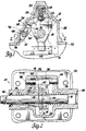
- a transmission selector mechanism generally designated 10, including a selector lever 12 secured to a selector shaft 14, and a plurality of gear selector rods 16, 18 and 20 consituting a I-2 selector rod 20, a 3-4 selector rod 18, and a 5-R selector rod 16.
- the selector lever 12 has three depressions 22, 24 and 26 formed therein which cooperate with a detent mechanism 28 to maintain the selector lever 12 in a position as selected by an operator by means of rotary manipulation of the selector shaft 14.
- the detent mechanism 28 includes a spring 30 which biases a detent ball 32, which ball 32 selectively engages the depressions formed in the selector lever 12.
- the selctor shaft 14 is slidably and rotatably disposed on a pair of bearings 34 and 36 which are secured in a selector housing 38.
- a seal 40 is disposed in the housing 38 to prevent the leakage of lubricant from the inside of the housing.
- the selector housing 38 is secured to a transmission housing 42 which houses a plurality of conventional transmission components, not shown.
- these transmission components include gear member which establish drive ratios (gear ratios) between the input and output shafts of a stepped-ratio transmission.
- the gear ratios are normally established with the aid of conventional synchroniser mechanisms which are manipulated by means of yokes that are operatively connected to the selector rods 16, 18 and 20. Inasmuch as such gearing arrangements are conventional and well-know, it does not appear necessary to provide detailed drawings or further descriptions thereof for an understanding of the present invention.
- the selector shaft 14 is manipulated linearly in the bearings 34 and 36 and rotatably in these bearings by means of a conventional shift tower, not shown.
- the selector lever 12 when viewed in the solid-line position of Figures I and 2, is operating in the neutral condition of the transmission selector macha- nism. In this neutral condition, the selector lever is free to move linearly in respective gates (slots) 44 formed in the selector rods 16, 18 and 20.
- selector lever 12 When the selector lever 12 is positioned in one of the slots 44, it is therby placed in a preselection position, and the selector shaft 14 may then be rotated from the respective preselection position to permit selection of either a first or second forward ratio by means of the selector rod 20, a third or fourth forward ratio by means of the selector rod 18, or a fifth forward or a reverse ratio by means of the selector rod 16.
- a reverse inhibitor mechanism is also disposed in the selector housing 38, and includes a rod (pin) 48, a spring 50 and an inhibitor lever 52.
- the inhibitor lever 52 is slidably and rotatably disposed on the rod 48, and the rod 48 is secured in the housing 38 by means of a press fit at 54.
- the inhibitor lever 52 is urged by means of the spring 50 to an "at rest” (set) position shown in Figures 3 and 4. In this "at rest” position, an abutment surface 56 of the inhibitor lever 52 abuts the inner wall of the selector housing 38.
- the inhibitor lever 52 is disposed in the "at rest” position whenever the transmission selector lever 12 is aligned with the 1-2 selector rod 20, or with the 3-4 selector rod 18, or is rotated to the fifth gear ratio-selected position.
- Figures 3 and 4 show the selector lever 12 when it has been rotated to the fifth gear ratio-selected position.
- the fifth gear ratio can be selected as shown in Figures 3 and 4.
- the inhibitor lever 52 will be moved linearly by the spring 50 along the rod 48 to the "at rest” position as seen in Figure 4, with the inhibitor lever 52 aligned with the selector lever 12.
- Rotation (pivoting) of the selector lever 12 from the fifth-ratio position to the neutral position will cause abutment between flat surfaces 60 on the selector lever 12 and a flat surface 62 on the inhibitor lever 52.
- This abutment and further pivoting of the lever 12 to the neutral position will cause pivoting of the inhibitor lever 52 on the rod 48 in opposition to the torsional force of the spring 50 until the upper portion 58 of the inhibitor lever 52 abuts the inner wall of the selector housing 38.
- This abutment prevents further pivoting of the selector lever 12 in a counterclockwise direction, as seen in Figure 5.
- the spring 50 is effective to control 3>0 the linear and the rotary positioning of the inhibitor lever 52 along the rod 48 until the "at rest" position is established.
- the spring 50 further provides the resistance (reaction forces) for the inhibitor lever 52 whenever linear movement to the position shown in Figure I or rotary movement to the position shown in Figure 5 occurs.
- the reverse inhibitor utilised herein involves only a minimum number of additional parts, namely three (that is, the rod 48, the spring 50 and the inhibitor lever 52), all of which may be manufactured by means of conventional processes. It may also be possible to reduce the amount of machining required, inasmuch as the only machining necessary on the lever 52 is machining of the bore in which the rod 48 is disposed. The portion 58, the su- face 56 and the surface 62 can however remain in an as-cast or as-forged condition.
- the rod 48 could in the alternative be bonded by the use of any one of a number of well-known commercially available adhesives. Assembly of the reverse inhibitor system within the transmission housing is thus relatively simple.
Landscapes
- Engineering & Computer Science (AREA)
- General Engineering & Computer Science (AREA)
- Mechanical Engineering (AREA)
- Gear-Shifting Mechanisms (AREA)
- Control Of Transmission Device (AREA)
Claims (5)
Applications Claiming Priority (2)
| Application Number | Priority Date | Filing Date | Title |
|---|---|---|---|
| US06/781,340 US4638678A (en) | 1985-09-30 | 1985-09-30 | Manual transmission shift control mechanism having a reverse inhibitor |
| US781340 | 1997-01-10 |
Publications (2)
| Publication Number | Publication Date |
|---|---|
| EP0219957A1 EP0219957A1 (fr) | 1987-04-29 |
| EP0219957B1 true EP0219957B1 (fr) | 1989-11-02 |
Family
ID=25122409
Family Applications (1)
| Application Number | Title | Priority Date | Filing Date |
|---|---|---|---|
| EP86306876A Expired EP0219957B1 (fr) | 1985-09-30 | 1986-09-05 | Mécanisme de changement de vitesse pour transmission à commande manuelle |
Country Status (5)
| Country | Link |
|---|---|
| US (1) | US4638678A (fr) |
| EP (1) | EP0219957B1 (fr) |
| JP (1) | JPS6280362A (fr) |
| CA (1) | CA1254489A (fr) |
| DE (1) | DE3666722D1 (fr) |
Cited By (2)
| Publication number | Priority date | Publication date | Assignee | Title |
|---|---|---|---|---|
| DE4432238A1 (de) * | 1994-09-10 | 1996-03-14 | Schaeffler Waelzlager Kg | Mechanisches Sperrsystem für eine axial verschiebbare und verdrehbare Welle |
| DE102008028494A1 (de) | 2008-06-14 | 2009-12-17 | Schaeffler Kg | Vorrichtung zum Vermeiden von Fehlschaltungen |
Families Citing this family (22)
| Publication number | Priority date | Publication date | Assignee | Title |
|---|---|---|---|---|
| US4721004A (en) * | 1987-01-16 | 1988-01-26 | Caterpillar Inc. | Transmission gear selector apparatus |
| US5036721A (en) * | 1990-09-28 | 1991-08-06 | General Motors Corporation | Shift control mechanism for a manual transmission |
| FR2669391B1 (fr) * | 1990-11-16 | 1993-03-05 | Peugeot | Dispositif de commande d'une boite de vitesse de vehicule automobile. |
| JP2564362Y2 (ja) * | 1992-01-14 | 1998-03-09 | ダイハツ工業株式会社 | 変速機のミスシフト防止機構 |
| US5224395A (en) * | 1992-08-05 | 1993-07-06 | Deere & Company | Transmission shift lever neutral lock |
| DE59303950D1 (de) * | 1992-08-10 | 1996-10-31 | Volkswagen Ag | Schalteinrichtung für ein Getriebe |
| FR2695598B1 (fr) * | 1992-09-16 | 1994-12-23 | Peugeot | Dispositif de commande d'une boîte de vitesses de véhicule automobile. |
| US5289734A (en) * | 1992-09-30 | 1994-03-01 | New Venture Gear, Inc. | Manual transmission shifter assembly with reverse inhibitor |
| IT1276412B1 (it) * | 1995-06-06 | 1997-10-31 | Paolo Paparoni | Perfezionamento ai dispositivi inibitori di innesto involontario di retromarcia, per comandi esterni di cambi di velocita' di autoveicoli. |
| DE19741633C1 (de) * | 1997-09-20 | 1999-03-25 | Ford Global Tech Inc | Schaltvorrichtung für ein Wechselgetriebe von Kraftfahrzeugen |
| JP2002340184A (ja) * | 2001-05-10 | 2002-11-27 | Honda Motor Co Ltd | 手動変速機 |
| US7793751B2 (en) * | 2005-04-01 | 2010-09-14 | Honda Motor Company, Ltd. | Vehicles including control assemblies having rotatable control knobs |
| US7654170B2 (en) * | 2005-08-26 | 2010-02-02 | Gm Global Technology Operations, Inc. | Centering spring apparatus for a transmission shift control mechanism |
| DE102006038740A1 (de) * | 2006-08-17 | 2008-02-21 | Schaeffler Kg | Schaltdom eines Getriebes, insbesondere eines Kraftfahrzeug-Schaltgetriebes |
| DE102009027533A1 (de) * | 2009-07-08 | 2011-01-20 | Zf Friedrichshafen Ag | Schaltvorrichtung eines Kraftfahrzeug-Schaltgetriebes |
| US9032830B2 (en) * | 2010-10-29 | 2015-05-19 | Ford Global Technologies, Llc | Transmission shift selector assembly |
| DE102012202890A1 (de) * | 2012-02-27 | 2013-08-29 | Zf Friedrichshafen Ag | Verschaltsicherung für ein Kraftfahrzeug-Schaltgetriebe |
| DE102013002684A1 (de) * | 2012-03-14 | 2013-09-19 | GM Global Technology Operations LLC (n. d. Gesetzen des Staates Delaware) | Innere Schaltbetätigung für ein Schaltgetriebe und Schaltgetriebe für ein Kraftfahrzeug |
| US9488272B2 (en) * | 2012-12-13 | 2016-11-08 | Eaton Corporation | Locking mechanism for a reverse shift rail of a transmission |
| FR3024197B1 (fr) * | 2014-07-24 | 2018-07-06 | Renault Sas | Commande de boite de vitesses manuelle de vehicule automobile |
| KR101673781B1 (ko) * | 2015-06-17 | 2016-11-07 | 현대자동차주식회사 | 차량용 변속 레버 장치 |
| JP6857822B2 (ja) * | 2017-01-23 | 2021-04-14 | 日本発條株式会社 | 船舶用シフト装置 |
Family Cites Families (12)
| Publication number | Priority date | Publication date | Assignee | Title |
|---|---|---|---|---|
| DE1750088A1 (de) * | 1968-03-28 | 1971-01-14 | Porsche Kg | Schaltvorrichtung fuer mehrstufige Geschwindigkeitswechselgetriebe |
| US3866488A (en) * | 1972-01-24 | 1975-02-18 | Toyota Motor Co Ltd | Manually operated shift assembly with restraining action for shifting to reverse |
| JPS522063B2 (fr) * | 1973-11-19 | 1977-01-19 | ||
| JPS5423060B2 (fr) * | 1973-12-29 | 1979-08-10 | ||
| JPS5423060A (en) * | 1977-07-23 | 1979-02-21 | Kawasaki Steel Co | Control device for roll crown while rolling |
| US4174644A (en) * | 1978-04-03 | 1979-11-20 | General Motors Corporation | Transmission and shift linkage |
| US4222283A (en) * | 1978-04-27 | 1980-09-16 | General Motors Corporation | Manual transmission lubrication system |
| GB2037914B (en) * | 1978-12-12 | 1982-11-10 | Honda Motor Co Ltd | Gear selector mechanism |
| JPS55103158A (en) * | 1979-01-30 | 1980-08-07 | Nissan Motor Co Ltd | Reversing error preventive mechanism |
| JPS55107159A (en) * | 1979-02-05 | 1980-08-16 | Aisin Seiki Co Ltd | Device for preventing erroneous driving and change-over operation |
| JPS6039907B2 (ja) * | 1979-12-29 | 1985-09-07 | 本田技研工業株式会社 | 車両用変速機の誤操作防止装置 |
| JPS6215556Y2 (fr) * | 1981-03-30 | 1987-04-20 |
-
1985
- 1985-09-30 US US06/781,340 patent/US4638678A/en not_active Expired - Lifetime
-
1986
- 1986-08-12 CA CA000515756A patent/CA1254489A/fr not_active Expired
- 1986-09-05 DE DE8686306876T patent/DE3666722D1/de not_active Expired
- 1986-09-05 EP EP86306876A patent/EP0219957B1/fr not_active Expired
- 1986-09-30 JP JP61230203A patent/JPS6280362A/ja active Pending
Cited By (2)
| Publication number | Priority date | Publication date | Assignee | Title |
|---|---|---|---|---|
| DE4432238A1 (de) * | 1994-09-10 | 1996-03-14 | Schaeffler Waelzlager Kg | Mechanisches Sperrsystem für eine axial verschiebbare und verdrehbare Welle |
| DE102008028494A1 (de) | 2008-06-14 | 2009-12-17 | Schaeffler Kg | Vorrichtung zum Vermeiden von Fehlschaltungen |
Also Published As
| Publication number | Publication date |
|---|---|
| EP0219957A1 (fr) | 1987-04-29 |
| CA1254489A (fr) | 1989-05-23 |
| JPS6280362A (ja) | 1987-04-13 |
| US4638678A (en) | 1987-01-27 |
| DE3666722D1 (en) | 1989-12-07 |
Similar Documents
| Publication | Publication Date | Title |
|---|---|---|
| EP0219957B1 (fr) | Mécanisme de changement de vitesse pour transmission à commande manuelle | |
| CA1150595A (fr) | Mecanisme de guidage et de detente pour commande de changement de vitesses | |
| US5109722A (en) | Self-detenting transmission shift key | |
| US4335623A (en) | Transmission shift control mechanism | |
| EP0117341A2 (fr) | Dispositif de commande de transmission | |
| US4193316A (en) | Transmission shift control mechanism | |
| US5272931A (en) | Transmission shift control mechanism | |
| US4307624A (en) | Transmission gear selector arm and sleeves for shifting forks | |
| GB2097493B (en) | Inhibiting movement of manual gearshift mechanism into reverse | |
| MX158833A (es) | Mejoras a mecanismo de cambio de velocidades de operacion manual para transmisiones de automoviles | |
| CA1180207A (fr) | Mecanisme a cames de changement de vitesses | |
| GB2149031A (en) | Transmission and range box control lever | |
| JPH0221472B2 (fr) | ||
| CS258206B1 (en) | Device for gear shifting and blocking | |
| EP0058965B1 (fr) | Boîte de vitesses ayant un levier à main | |
| EP0058966A3 (fr) | Mécanisme de sélection de la marche arrière dans une boíte de vitesse | |
| US4648283A (en) | Gear shift control mechanism | |
| EP0139261A2 (fr) | Mécanisme de commande d'une boîte de changement de vitesses manuelle pour un véhicule | |
| US4827792A (en) | Transmission shift control mechanism | |
| GB2168117A (en) | A shifting arrangement for a motor vehicle change-speed transmission | |
| EP0058969B1 (fr) | Transmission de véhicule à commande manuelle | |
| GB2183753B (en) | Gear-shifting mechanism | |
| GB1525688A (en) | Gearshift mechanism for a changespeed gear transmission for motor vehicles | |
| EP0059398A2 (fr) | Mécanisme de commande d'une boîte de changement de vitesses manuelle pour un véhicule | |
| EP0722059A3 (fr) | Verrouillage avec fente de déactivation |
Legal Events
| Date | Code | Title | Description |
|---|---|---|---|
| PUAI | Public reference made under article 153(3) epc to a published international application that has entered the european phase |
Free format text: ORIGINAL CODE: 0009012 |
|
| 17P | Request for examination filed |
Effective date: 19860917 |
|
| AK | Designated contracting states |
Kind code of ref document: A1 Designated state(s): DE GB |
|
| 17Q | First examination report despatched |
Effective date: 19880819 |
|
| GRAA | (expected) grant |
Free format text: ORIGINAL CODE: 0009210 |
|
| AK | Designated contracting states |
Kind code of ref document: B1 Designated state(s): DE GB |
|
| REF | Corresponds to: |
Ref document number: 3666722 Country of ref document: DE Date of ref document: 19891207 |
|
| PGFP | Annual fee paid to national office [announced via postgrant information from national office to epo] |
Ref country code: GB Payment date: 19900813 Year of fee payment: 5 |
|
| PLBE | No opposition filed within time limit |
Free format text: ORIGINAL CODE: 0009261 |
|
| STAA | Information on the status of an ep patent application or granted ep patent |
Free format text: STATUS: NO OPPOSITION FILED WITHIN TIME LIMIT |
|
| 26N | No opposition filed | ||
| PGFP | Annual fee paid to national office [announced via postgrant information from national office to epo] |
Ref country code: DE Payment date: 19901024 Year of fee payment: 5 |
|
| PG25 | Lapsed in a contracting state [announced via postgrant information from national office to epo] |
Ref country code: GB Effective date: 19910905 |
|
| GBPC | Gb: european patent ceased through non-payment of renewal fee | ||
| PG25 | Lapsed in a contracting state [announced via postgrant information from national office to epo] |
Ref country code: DE Effective date: 19920602 |