EP0219959B1 - Gesteinsbohrer mit verschleissbeständigen Einsätzen - Google Patents
Gesteinsbohrer mit verschleissbeständigen Einsätzen Download PDFInfo
- Publication number
- EP0219959B1 EP0219959B1 EP86306897A EP86306897A EP0219959B1 EP 0219959 B1 EP0219959 B1 EP 0219959B1 EP 86306897 A EP86306897 A EP 86306897A EP 86306897 A EP86306897 A EP 86306897A EP 0219959 B1 EP0219959 B1 EP 0219959B1
- Authority
- EP
- European Patent Office
- Prior art keywords
- tungsten carbide
- layer
- rock bit
- diamond
- cone
- Prior art date
- Legal status (The legal status is an assumption and is not a legal conclusion. Google has not performed a legal analysis and makes no representation as to the accuracy of the status listed.)
- Expired
Links
Images

Classifications
-
- E—FIXED CONSTRUCTIONS
- E21—EARTH OR ROCK DRILLING; MINING
- E21B—EARTH OR ROCK DRILLING; OBTAINING OIL, GAS, WATER, SOLUBLE OR MELTABLE MATERIALS OR A SLURRY OF MINERALS FROM WELLS
- E21B10/00—Drill bits
- E21B10/46—Drill bits characterised by wear resisting parts, e.g. diamond inserts
- E21B10/56—Button-type inserts
- E21B10/567—Button-type inserts with preformed cutting elements mounted on a distinct support, e.g. polycrystalline inserts
- E21B10/573—Button-type inserts with preformed cutting elements mounted on a distinct support, e.g. polycrystalline inserts characterised by support details, e.g. the substrate construction or the interface between the substrate and the cutting element
- E21B10/5735—Interface between the substrate and the cutting element
-
- B—PERFORMING OPERATIONS; TRANSPORTING
- B22—CASTING; POWDER METALLURGY
- B22F—WORKING METALLIC POWDER; MANUFACTURE OF ARTICLES FROM METALLIC POWDER; MAKING METALLIC POWDER; APPARATUS OR DEVICES SPECIALLY ADAPTED FOR METALLIC POWDER
- B22F7/00—Manufacture of composite layers, workpieces, or articles, comprising metallic powder, by sintering the powder, with or without compacting wherein at least one part is obtained by sintering or compression
- B22F7/06—Manufacture of composite layers, workpieces, or articles, comprising metallic powder, by sintering the powder, with or without compacting wherein at least one part is obtained by sintering or compression of composite workpieces or articles from parts, e.g. to form tipped tools
-
- C—CHEMISTRY; METALLURGY
- C22—METALLURGY; FERROUS OR NON-FERROUS ALLOYS; TREATMENT OF ALLOYS OR NON-FERROUS METALS
- C22C—ALLOYS
- C22C26/00—Alloys containing diamond or cubic or wurtzitic boron nitride, fullerenes or carbon nanotubes
-
- E—FIXED CONSTRUCTIONS
- E21—EARTH OR ROCK DRILLING; MINING
- E21B—EARTH OR ROCK DRILLING; OBTAINING OIL, GAS, WATER, SOLUBLE OR MELTABLE MATERIALS OR A SLURRY OF MINERALS FROM WELLS
- E21B10/00—Drill bits
- E21B10/46—Drill bits characterised by wear resisting parts, e.g. diamond inserts
- E21B10/50—Drill bits characterised by wear resisting parts, e.g. diamond inserts the bit being of roller type
- E21B10/52—Drill bits characterised by wear resisting parts, e.g. diamond inserts the bit being of roller type with chisel- or button-type inserts
-
- E—FIXED CONSTRUCTIONS
- E21—EARTH OR ROCK DRILLING; MINING
- E21B—EARTH OR ROCK DRILLING; OBTAINING OIL, GAS, WATER, SOLUBLE OR MELTABLE MATERIALS OR A SLURRY OF MINERALS FROM WELLS
- E21B10/00—Drill bits
- E21B10/46—Drill bits characterised by wear resisting parts, e.g. diamond inserts
- E21B10/56—Button-type inserts
- E21B10/567—Button-type inserts with preformed cutting elements mounted on a distinct support, e.g. polycrystalline inserts
- E21B10/5673—Button-type inserts with preformed cutting elements mounted on a distinct support, e.g. polycrystalline inserts having a non planar or non circular cutting face
-
- B—PERFORMING OPERATIONS; TRANSPORTING
- B22—CASTING; POWDER METALLURGY
- B22F—WORKING METALLIC POWDER; MANUFACTURE OF ARTICLES FROM METALLIC POWDER; MAKING METALLIC POWDER; APPARATUS OR DEVICES SPECIALLY ADAPTED FOR METALLIC POWDER
- B22F2998/00—Supplementary information concerning processes or compositions relating to powder metallurgy
Definitions
- This invention relates to rock bits for drilling oil wells or the like having polycrystalline diamond (PCD) tipped inserts for drilling a rock formation.
- PCD polycrystalline diamond
- Heavy duty rock bits are employed for drilling wells in subterranean formation for oil, gas, geothermal steam and the like.
- Such bits have a body connected to a drill string and a plurality, typically three, of hollow cutter cones mounted on the body for drilling rock formations.
- the cutter cones are mounted on steel journals or pins integral with the body at its lower end.
- the drill string and bit body are rotated in the bore hole and each cone is caused to rotate on its respective journal as the cone contracts the bottom of the bore hole being drilled.
- a rock bit is used in hard, tough formations, high pressures and temperatures are encountered.
- the total useful life of a rock bit in such severe environments is in the order of 20 to 200 hours for bits in size of about 16.5 cm (6.5 inch) to 31 cm (12.25 inch) diameter at depths of about 1524 m (5,000 feets) to 6096 m (20,000 feet). Useful lifetimes of about 65 to 150 hours are typical.
- Replacement of a drill bit can be required for a number or reasons, including wearing out or breakage of the structure contacting the rock formation.
- the other principal reason for replacing a rock bit on a drill string is that the bearings supporting one or more of the roller cones fail due to excessive wear, loss of lubricant or the like.
- gage row The outermost row of inserts on each cone of a rock bit is known as the gage row. This row of inserts is subjected to the greatest wear since it travels furthest on the bottom of the hole, and the gage row inserts also tend to rub on the sidewall of the hole as the cones rotate on the drill bit body. As the gage row inserts wear, the diameter of the bore hole being drilled may decrease below the original gage of the rock bit. When the bit is worn out and removed, a bottom portion of the hole is usually under gage.
- the rate of penetration of a rock bit into the rock formation being drilled is an important parameter for drilling. Clearly, it is desirable to maintain a high rate of drilling since this reduces the time required to drill the well, and such time is quite expensive because of the fixed costs involved in drilling.
- the rate of penetration decreases when the inserts in the cones become worn and do not protrude from the cone surface to the same extent they did when drilling commences.
- the worn inserts have an increased radius of curvature and increased contact area on the rock. It therefore takes greater force to penetrate and this may cause both bearing failure and gage row insert breakage. Drilling rate is continually observed by the driller and when the inserts are worn to the point that the rate of penetration is unacceptably low, the bit is replaced.
- Wear resistance of conventional inserts of cemented tungsten carbide may be enhanced by increasing the proportion of tungsten carbide and decreasing the proportion of cobalt in the composite material. This increases the hardness and wear resistance of the cemented tungsten carbide but reduces its toughness so that the inserts are more susceptible to breakage than inserts with higher cobalt content.
- the cobalt content of inserts for use in rock bits ranges from about 6% to 16% by weight cobalt.
- particle size of the tungsten carbide phase is another factor that influences wear resistance and toughness.
- Exemplary particle size in an insert is in the range of from three to seven microns. This particle size is an average particle size of a powder mixture that includes larger and smaller particles. For example, when the average particle size is five microns, there are submicron size particles present as well as particles as large as seven or eight microns. Generally speaking toughness increases with larger particle size and so does wear resistance.
- a common grade of cemented tungsten carbide for rock bit inserts has an average tungsten carbide particle size of about six microns and contains about 10% to 14% by weight cobalt.
- Toughness of the inserts is important in a rock bit since the inserts are subjected to impact loads as the cones rotate, as well as wear by rubbing against the rock formation. Breakage of inserts can be a substantial problem since it not only results in reduced drilling activity, but the fragments of a broken insert may damage other inserts. It is therefore desirable to provide inserts that are hard to resist wear and tough to resist breakage.
- a rock bit comprising: a steel body; means at one end of the body for connecting the bit to a drill string; means at the opposite end of the body for mounting at least one roller cone on the body for rotation around an axis transverse to the axis of the bit; at least one roller cone so mounted on the body for rolling on the bottom of a bore hole being drilled; a plurality of inserts in such a cone for crushing rock at the bottom of such a bore hole, at least a portion of such inserts comprising: a cemented tungsten carbide body having a grip length embedded in the cone and a converging end portion protruding from the surface of the cone; characterised by a polycrystalline diamond layer on the converging end of the carbide body; and at least one transition layer between the polycrystalline diamond layer and the carbide body, the transition layer comprising a composite containing diamond crystals and precemented tungsten carbide particles.
- An exemplary rock bit comprises a steel body 10 having three cutter cones 11 mounted on its lower end.
- a threaded pin 12 is at the upper end of the body for assembly of the rock bit onto a drill string for drilling oil wells or the like.
- a plurality of tungsten carbide inserts 13 are provided in the surfaces of the cutter cones for bearing on rock formation being drilled.
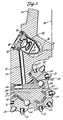
- FIG. 2 is a fragmentary longitudinal cross section of the rock bit extending radially from the rotational axis 14 of the rock bit through one of the three legs on which the cutter cones 11 are mounted.
- Each leg includes a journal pin 16 extending downwardly and radially inwardly of the rock bit body.
- the journal pin includes a cylindrical bearing surface having a hard metal insert 17 on a lower portion of the journal pin.
- the hard metal insert is typically a cobalt or iron base alloy welded in place in a groove on the journal leg and having a substantially greater hardness than the steel forming the journal pin and rock bit body.
- An open groove 18 corresponding to the insert 17 is provided on the upper portion of the journal pin. Such a groove can, for example, extend around 60% or so of the circumference of the journal pin and the hard metal 17 can extend around the remaining 40% or so.
- the journal pin also has a cylindrical nose 19 at its lower end.
- Each cutter cone 11 is in the form of a hollow generally conical steel body having tungsten carbide inserts 13 pressed into holes on the external surface.
- the outer row of inserts 20 on each cone is referred to as the gage row since these inserts drill at the gage or outer diameter of the bore hole.
- Such tungsten carbide inserts provide the drilling action by engaging and crushing subterranean rock formation on the bottom of a bore hole being drilled as the rock bit is rotated.
- the cavity in the cone contains a cylindrical bearing surface including an aluminum bronze insert 21 deposited in a groove in the steel of the cone or as a floating insert in a groove in the cone.
- the aluminum bronze insert 21 in the cone engages the hard metal insert 17 on the leg and provides the main bearing surface for the cone on the bit body.
- a nose button 22 is between the end of the cavity in the cone and the nose 19, and carries the principal thrust loads of the cone on the journal pin.
- a bushing 23 surrounds the nose and provides additional bearing surface between the cone and journal pin.
- a plurality of bearing balls 24 are fitted into complementary ball races in the cone and on the journal pin. These balls are inserted through a ball passage 26 which extends through the journal pin between the bearing races and the exterior of the rock bit.
- a cone is first fitted on the journal pin and then the bearing balls 24 are inserted through the ball passage. The balls carry any thrust loads tending to remove the cone from the journal pin and thereby retain the cone on the journal pin.
- the balls are retained in the races by a ball retainer 27 inserted through the ball passage 26 after the balls are in place.
- a plug 28 is then welded into the end of the ball passage to keep the ball retainer in place.
- the bearing surfaces between the journal pin and cone are lubricated by a grease which fills the regions adjacent the bearing surfaces plus various passages and a grease reservoir.
- the grease reservoir comprises a cavity 29 in the rock bit body which is connected to the ball passage 26 by a lubricant passage 31.
- Grease also fills the portion of the ball passage adjacent the ball retainer, the open groove 18 on the upper side of the journal pin and a diagonally extending passage 32 therebetween. Grease is retained in the bearing structure by a resilient seal in the form of an O-ring 33 between the cone and journal pin.
- a pressure compensation subassembly is included in the grease reservoir 29.
- This subassembly comprises a metal cup 34 with an opening 36 at its inner end.
- a flexible rubber bellows 37 extends into the cup from its outer end. The bellows is held in place by a cap 38 having a vent passage 39 therethrough.
- the pressure compensation subassembly is held in the grease reservoir by a snap ring 41.
- the bellows has a boss 42 at its inner end which can seat against the cap 38 at one end of the displacement of the bellows for sealing the vent passage 39.
- the end of the bellows can also seat against the cup 34 at the other end of its stroke, thereby sealing the opening 36.
- At least a portion of the cutting structure of the rock bit comprises tungsten carbide inserts that are tipped with polycrystalline diamond.
- An exemplary insert is illustrated in longitudinal cross section in FIG. 3. Such an insert has a cylindrical grip length 46 extending along a major portion of the insert.
- a converging portion 47 which may have any of a variety of shapes depending on the desired cutting structure.
- the converging portion may be referred to as a projectile shape or basically a cone with a rounded end. It may be a chisel shape which is like a cone with converging flats cut on opposite sides and a rounded end.
- the converging portion may be hemispherical or any of a variety of other shapes known in the art.
- Such an insert is press fitted or brazed into the roller cone.
- Each one of the cones has a plurality of flat bottomed holes in circumferential rows on its outer surface.
- An exemplary hole has a diameter about 0.13 millimeters smaller than the diameter of the grip 46 of an exemplary insert.
- the insert is pressed into the hole in the steel cone with many thousand pounds of force. This press fit of the insert into the cone tightly secures the insert in place and prevents it from being dislodged during drilling.
- the converging portion of the insert illustrated in FIG. 3, has an outer layer 48 for engaging rock when the insert is used in a rock bit, and an inner layer 49 between the outer layer and the main cemented tungsten carbide body of the insert.
- the outer layer in an exemplary embodiment comprises polycrystalline diamond (PCD) with a thickness of 125 microns.
- the inner layer has a thickness of 380 microns and comprises a composite material of polycrystalline diamond and precemented tungsten carbide, such as disclosed in US-A-4,525,178.
- PCD polycrystalline diamond
- the term polycrystalline diamond, along with its abbreviation "PCD" refers to the material produced by subjecting individual diamond crystals to sufficiently high pressure and high temperature that intercrystalline bonding occurs between adjacent diamond crystals.
- Exemplary minimum temperature is about 1300°C and an exemplary minimum pressure is about 35 kilobars.
- the minimum sufficient temperature and pressure in a given embodiment may depend on other parameters such as the presence of a catalytic material, such as cobalt, with the diamond crystals. Generally such a catalyst/binder material is used to assure intercrystalline bonding at a selected time, temperature and pressure of processing.
- PCD refers to the polycrystalline diamond including residual cobalt. Sometimes PCD is referred to in the art as "sintered diamond".
- the outer layer of PCD is made from a mixture of diamond crystals and cobalt powder, with 13% by weight or 6% by volume of cobalt in the total mixture.
- the catalyst metal is present in the range of from one to ten percent by volume.
- About 65% of the diamond crystals are in the range of four to eight microns.
- the other 35% of the diamond crystals are in the range of one-half to one micron.
- the diamond crystals may be either naturally occurring diamonds or synthetic diamonds produced by a high temperature, high pressure process.
- the diamond crystal size can range upwardly from submicron sizes. Preferably they range up to about twenty microns. Preferably a mix of sizes is used for dense packing.
- the cobalt content can be in the range of from one to fifteen percent by volume, preferably less than about ten percent by volume. In some embodiments other catalyst metals such as iron or nickel may be used.
- the raw materials for making the PCD layer are preferably milled together for a sufficient time to thoroughly coat the diamond particles with cobalt. Milling in a ball mill lined with cemented tungsten carbide and using cemented tungsten carbide balls is preferred to avoid contamination of the diamond. An attritor or planetary mill may be used if desired. Such milling should be sufficiently energetic to "smear" the cobalt but should avoid appreciable comminution of the diamond particles. One or two days of ball milling is appropriate.
- Intercrystalline bonding between adjacent diamonds occurs and a unitary solid polycrystalline diamond article is formed when the milled materials are subjected to high temperature and a sufficient pressure that diamond is thermodynamically stable.
- the intermediate composite layer is formed of a mixture of diamond crystals, cobalt, and precemented tungsten carbide particles.
- the precemented tungsten carbide is made by blending tungsten carbide powder and cobalt powder in a ball mill or the like. The blended powders are compacted and sintered near the melting point of cobalt. The resultant compact is comminuted to the desired particle size for use in making the composite material of the inner layer. In an exemplary embodiment a grit size of -325 U. S. mesh (about 44 microns) is used in the composite material of the inner layer.
- the precemented tungsten carbide grit can have a variety of tungsten carbide particle sizes and shapes, and various cobalt contents.
- the cobalt content can be in the range of from five to sixteen percent by weight and the tungsten carbide particles are preferably in the range of from four to fifteen microns. In an exemplary embodiment the particle size is six microns and the cobalt content is fourteen percent by weight.
- the inner layer between the layer of polycrystalline diamond and the cemented tungsten carbide substrate is made from a mixture of forty percent by volume of the aforementioned diamond powder (containing six percent by volume cobalt) and sixty percent by volume precemented tungsten carbide grit. If desired, additional cobalt can be included depending on the cobalt content of the cemented tungsten carbide.
- the diamond crystals and cobalt powder are ball milled together as hereinabove described. After initial milling cemented tungsten carbide grit is added, with or without additional cobalt, and the mixture is further milled for thoroughly blending and smearing the mixture.
- diamond and cobalt powders may be ball milled together for up to a day before addition of tungsten carbide grit. This mixture is then ball milled for another one or two days. Forty-eight hours in an exemplary ball milling time.
- the blended powders for making the layers on the insert are sintered and bonded to a rock bit insert blank 51 in an assembly of the type illustrated in FIG. 5.
- the insert being formed in the embodiment illustrated in FIG. 5 has layers somewhat different from those in the embodiment of FIG. 3 as hereinafter described, but the manufacturing technique is the same.
- the insert blank 51 comprises a cylindrical cemented tungsten carbide body having a converging portion at one end.
- the converging portion has the geometry of the completed insert, less the thickness of the layers to be formed thereon.
- the assembly is formed in a deep drawn metal cup which preferably has double walls.
- the inner cup is zirconium sheet having a thickness of 50 to 125 microns.
- the outer cup 53 is molybdenum with a thickness of 250 microns.
- a zirconium sheet 54 and molybdenum sheet 55 close the assembly at the top.
- the zirconium "can” thus formed protects material within it from the effects of nitrogen and oxygen.
- the molybdenum can protects the zirconium from water which is often present during the high pressure, high temperature pressing cycle used to form the rock bit insert.
- blended diamond powder including cobalt may be placed in the cup and spread into a thin layer by rotation and pressing with an object having the same shape as the insert blank when the blank is axisymmetric. If a chisel insert is being made, the powder can be spread with a generally conical tool. Powder to make the outer layer is spread first, then powder to make the inner layer may be spread on the outer layer. Finally the insert blank is put in place and the metal sheets are added to close the top of the assembly. A small amount of paraffin wax may be included in the blended powders to aid distribution and retention of the powder in thin layers. Alternatively layers can be built up on the end of the insert blank before insertion into the cup.
- sufficient wax may be included with the powders to form self-supporting "caps" of blended powder to be placed on the insert blank or in the cups. After assembly is made by one of such techniques, it is preferable to press the assembly through a die to swage the cups tightly against their contents.
- One or more of such assemblies is then placed in a conventional high pressure cell for pressing in a belt press or cubic press.
- a variety of known cell configurations are suitable.
- An exemplary cell has a graphite heater tube surrounding such an assembly and insulated from it by salt or pyrophyllite for sealing the cell and transmitting pressure.
- Such a cell, including one or more such assemblies for forming a rock bit insert, is placed in a high pressure belt or cubic press and sufficient pressure is applied that diamond is thermodynamically stable at the temperatures involved in the sintering process. In an exemplary embodiment, a pressure of 50 kilobars is used.
- the grip of the completed insert may be diamond ground to a cylinder of the desired size for fitting in a hole in the cone of a rock bit.
- the composite layer of diamond crystals and precemented carbide particles is, of course, sintered by high temperature and pressure and is no longer in the form of discrete particles that could be separated from each other.
- FIG. 4 illustrates another embodiment of rock bit insert tipped with polycrystalline diamond as provided in practice of this invention.
- This insert has a conventional cemented tungsten carbide blank 57 with a cylindrical grip 58 and a converging end on the portion of the insert that protrudes beyond the surface of the cone in which it is pressed.
- the inner layer is overlain by an intermediate layer 60 that is 250 microns thick. This in turn is overlain by an outer layer 61 that is 125 microns thick.
- the outer layer 61 is PCD as hereinabove described.
- the intermediate layer is formed of a mixture of 60% by volume PCD (including 6% by volume cobalt) and 40% by volume precemented tungsten carbide.
- the inner layer is formed of a mixture of 40% by volume PCD and 60% by volume precemented tungsten carbide.
- the volume percentages may differ slightly from the proportions in the original mixture due to interactions. For example, some of the diamond may dissolve in the cobalt phase, thereby slightly reducing the volume proportion of diamond in the PCD and composite.
- the intermediate layer 60 near the PCD layer has a relatively higher proportion of PCD and lower proportion of cemented carbide than the inner layer 59, thereby providing a transition between the outer layer and cemented carbide blank in two steps instead of the single step in the embodiment hereinabove described and illustrated in FIG. 3.
- FIG. 5 illustrates still another embodiment of insert as provided in practice of this invention.
- the converging portion of the insert blank 51 has an outer layer 63 of polycrystalline diamond.
- This outer PCD layer is separated from the blank by an inner layer 64 having a gradual transition of properties between the PCD layer and the cemented carbide blank.
- Such a transition layer has a high proportion of PCD (e.g., 80% or more by volume) and low proportion of cemented tungsten carbide adjacent to the outer PCD layer 63.
- the polycrystalline diamond content adjacent to the blank may be 20% by volume and the precemented tungsten carbide content may be 80% by volume.
- a gradual transition in proportion of diamond in the transition layer provides, in effect, a very large number of steps in mechanical properties between the outer PCD layer and the cemented tungsten carbide substrate.
- the transition layer provides a transition in a variety of important properties of the PCD layer and carbide substrate. It compensates for differences in coefficient of thermal expansion and modulus of elasticity. It has a sonic velocity intermediate between the PCD and carbide which means that a stress wave travelling through the insert has less stress concentration at the interface.
- a transition layer of diamond crystals and precemented tungsten carbide particles is significantly different from a mere mixture of diamond, cobalt and carbide powders. It is believed that the precemented carbide particles act as a plurality of "mini-anvils" that provide a pressure distribution in the layer very different from the pressure distribution in a mix of powders, resulting in better compaction.
- the precemented carbide has less shrinkage than a powder mixture, improving the rheology of pressing. Further, the distribution of carbide in the composite is rather different from a powder; an analogy could be use of steel reinforcing bar in concrete as compared with powdered steel. Significantly different properties can result from the difference in distribution.
- the outer PCD layer has a thickness of about 125 microns and thicker layers can be employed if desired.
- the PCD layer can be in the range of 75 to 600 microns thick. Surprisingly, however, since the PCD is extremely resistant to erosion by rock formations being drilled, a layer only 125 microns thick is adequate for a long life rock bit.
- the thickness of the transition layer, or layers can range from 100 microns to 3 millimeters or more. Other proportions of PCD and precemented carbide particles in the transition layers may also be used as desired.
- these layers can range from 5 to 95% by volume polycrystalline diamond and from 95 to 5% precemented tungsten carbide.
- additional cobalt may be included in the mixture for good sintering of the transition layer.
- Other metal carbides such as tantalum carbide or titanium carbide may be suitable in some embodiments.
Landscapes
- Engineering & Computer Science (AREA)
- Geology (AREA)
- Mining & Mineral Resources (AREA)
- Life Sciences & Earth Sciences (AREA)
- Chemical & Material Sciences (AREA)
- Mechanical Engineering (AREA)
- Physics & Mathematics (AREA)
- Fluid Mechanics (AREA)
- Environmental & Geological Engineering (AREA)
- General Life Sciences & Earth Sciences (AREA)
- Geochemistry & Mineralogy (AREA)
- Crystallography & Structural Chemistry (AREA)
- Materials Engineering (AREA)
- Metallurgy (AREA)
- Organic Chemistry (AREA)
- Composite Materials (AREA)
- Manufacturing & Machinery (AREA)
- Earth Drilling (AREA)
Claims (12)
- Gesteinsbohrer:
mit einem Stahlkörper (10),
mit Mitteln (12) an dem einen Ende des Körpers (10) zur Verbindung des Bohrers mit einer Bohrstange,
mit Mitteln (16) an dem entgegengesetzten Ende des Körpers (10) zur Befestigung von wenigstens einem Walzenkegel (11) auf dem Körper (10) zur Drehung um eine Achse, die quer zu der Achse des Bohrers verläuft,
mit mindestens einem in solcher Weise auf dem Körper (10) befestigten Walzenkegel (11 ), um auf dem Boden eines zu bohrenden Bohrlochs abzurollen,
mit einer Vielzahl von Einsätzen (13) in solch einem Kegel (11) zum Zerbrechen von Gestein an dem Boden eines solchen Bohrlochs, wobei mindestens ein Teil dieser Einsätze (13) umfaßt:
einen zementierten Wolframkarbidkörper, der mit einer Anhaftungslänge in dem Kegel (11) eingebettet ist und bei dem ein zusammenlaufender Endabschnitt aus der Oberfläche des Kegels (11) herausragt,
gekennzeichnet durch eine polykristalline Diamantschicht (48) auf dem zusammenlaufenden Ende des Karbidkörpers, und
mindestens einer Übergangsschicht (49) zwischen der polykristallinen Diamantschicht (48) und dem Karbidkörper, wobei die Übergangsschicht (49) eine Verbindung aus Diamantkristallen und vorzementierten Wolframkarbid-Teilchen umfaßt. - Gesteinsbohrer nach Anspruch 1, dadurch gekennzeichnet, daß die Übergangsschicht (49) 40 Volumenprozent polykristallinen Diamant und 60 Volumenprozent vorzementierte Wolframkarbid-Teilchen umfaßt.
- Gesteinsbohrer nach Anspruch 2, dadurch gekennzeichnet, daß die polykristalline Diamantschicht (48) von 1 - 10 Volumenprozent Kobalt enthält.
- Gesteinsbohrer nach einem der Ansprüche 1 bis 3, dadurch gekennzeichnet, daß die polykristalline Diamantschicht (48) eine Dicke im Bereich von 75 - 600 Mikrometer aufweist.
- Gesteinsbohrer nach Anspruch 4, dadurch gekennzeihnet, daß die Übergangsschicht (49) eine Dicke im Bereich von 100 - 600 Mikrometer aufweist.
- Gesteinsbohrer nach Anspruch 5, dadurch gekennzeichnet, daß die Übergangsschicht (49) zwischen 5 und 95 Volumenprozent Diamant und zwischen 95 - 5 Volumenprozent vorzementiertes Wolframkarbid enthält.
- Gesteinsbohrer nach einem der vorstehenden Ansprüche, dadurch gekennzeichnet, daß er eine zweite Übergangsschicht (59) zwischen der ersten Übergangsschicht (60) und dem zementierten Wolframkarbidkörper aufweist, wobei die zweite Übergangsschicht (59) eine Verbindung aus einem niedrigeren Anteil von Diamantkristallen und einem höheren Anteil von vorzementiertem Wolframkarbid als in der ersten Übergangsschicht (60) aufweist.
- Gesteinsbohrer nach einem der Ansprüche 1 bis 6, dadurch gekennzeichnet, daß die Übergangsschicht (64) einen verlaufenden Übergang zwischen einem relativ höheren Diamantgehalt und einem relativ geringeren vorzementierten Wolframkarbidgehalt in der Nähe der polykristallinen Diamantschicht (63) und zwischen einem relativ niedrigeren Diamantgehalt und einem relativ höheren vorzementierten Wolframkarbidgehalt in der Nähe des Wolframkarbidkörpers aufweist.
- Gesteinsbohrer nach einem der vorstehenden Ansprüche, dadurch gekennzeichnet, daß die Einsätze (13) in einer Eichabstandsreihe von Einsätzen in solch einem Kegel (11) angeordnet sind.
- Gesteinsbohrer nach Anspruch 9, dadurch gekennzeichnet, daß die Einsätze (13) innerhalb der abstandseichend ausgerichteten Einsätze zementiertes Wolframkarbid ohne eine Schicht von polykristallinem Diamant umfassen.
- Gesteinsbohrer nach einem der vorstehenden Ansprüche, dadurch gekennzeichnet, daß solch ein Einsatz (13) einen zusammenlaufenden Endabschnitt aufweist, der aus der Gruppe der Abschnitte mit einer projektilförmigen Gestalt, mit einem Kegel mit abgerundetem Ende, mit einer Meißelform und mit einer halbkugelförmigen Gestalt besteht.
- Gesteinsbohrer nach einem der vorstehenden Ansprüche, dadurch gekennzeichnet, daß im wesentlichen der gesamte zusammenlaufende Abschnitt eines solchen Einsatzes (13) eine polykristalline Diamantschicht (48) und eine Übergangsschicht aufweist, die Diamantkristalle und vorzementiertes Wolframkarbid zwischen der Diamantschicht (48) und dem zementiertem Wolframkarbidkörper aufweist.
Applications Claiming Priority (2)
| Application Number | Priority Date | Filing Date | Title |
|---|---|---|---|
| US78912085A | 1985-10-18 | 1985-10-18 | |
| US789120 | 1985-10-18 |
Publications (3)
| Publication Number | Publication Date |
|---|---|
| EP0219959A2 EP0219959A2 (de) | 1987-04-29 |
| EP0219959A3 EP0219959A3 (en) | 1988-10-19 |
| EP0219959B1 true EP0219959B1 (de) | 1992-04-29 |
Family
ID=25146652
Family Applications (1)
| Application Number | Title | Priority Date | Filing Date |
|---|---|---|---|
| EP86306897A Expired EP0219959B1 (de) | 1985-10-18 | 1986-09-05 | Gesteinsbohrer mit verschleissbeständigen Einsätzen |
Country Status (5)
| Country | Link |
|---|---|
| EP (1) | EP0219959B1 (de) |
| JP (1) | JPS62111093A (de) |
| CA (1) | CA1256096A (de) |
| DE (1) | DE3685083D1 (de) |
| IE (1) | IE57504B1 (de) |
Cited By (3)
| Publication number | Priority date | Publication date | Assignee | Title |
|---|---|---|---|---|
| US8292006B2 (en) | 2009-07-23 | 2012-10-23 | Baker Hughes Incorporated | Diamond-enhanced cutting elements, earth-boring tools employing diamond-enhanced cutting elements, and methods of making diamond-enhanced cutting elements |
| US8695733B2 (en) | 2009-08-07 | 2014-04-15 | Smith International, Inc. | Functionally graded polycrystalline diamond insert |
| US8758463B2 (en) | 2009-08-07 | 2014-06-24 | Smith International, Inc. | Method of forming a thermally stable diamond cutting element |
Families Citing this family (20)
| Publication number | Priority date | Publication date | Assignee | Title |
|---|---|---|---|---|
| GB8725671D0 (en) * | 1987-11-03 | 1987-12-09 | Reed Tool Co | Manufacture of rotary drill bits |
| GB2273306B (en) * | 1992-12-10 | 1996-12-18 | Camco Drilling Group Ltd | Improvements in or relating to cutting elements for rotary drill bits |
| GB2274474B (en) * | 1993-01-21 | 1996-07-31 | Camco Drilling Group Ltd | Improvements in or relating to cutter assemblies for rotary drill bits |
| US5370195A (en) * | 1993-09-20 | 1994-12-06 | Smith International, Inc. | Drill bit inserts enhanced with polycrystalline diamond |
| US5924501A (en) * | 1996-02-15 | 1999-07-20 | Baker Hughes Incorporated | Predominantly diamond cutting structures for earth boring |
| US5706906A (en) * | 1996-02-15 | 1998-01-13 | Baker Hughes Incorporated | Superabrasive cutting element with enhanced durability and increased wear life, and apparatus so equipped |
| US5743346A (en) * | 1996-03-06 | 1998-04-28 | General Electric Company | Abrasive cutting element and drill bit |
| US5954147A (en) * | 1997-07-09 | 1999-09-21 | Baker Hughes Incorporated | Earth boring bits with nanocrystalline diamond enhanced elements |
| US6073711A (en) * | 1997-08-18 | 2000-06-13 | Sandvik Ab | Partially enhanced drill bit |
| CA2770308C (en) | 2009-08-07 | 2017-11-28 | Smith International, Inc. | Diamond transition layer construction with improved thickness ratio |
| CN102648328B (zh) * | 2009-08-07 | 2015-02-18 | 史密斯国际有限公司 | 具有高的韧度和高的耐磨性的多晶金刚石材料 |
| WO2011017607A2 (en) | 2009-08-07 | 2011-02-10 | Smith International, Inc. | Highly wear resistant diamond insert with improved transition structure |
| US8851205B1 (en) | 2011-04-08 | 2014-10-07 | Hard Rock Solutions, Llc | Method and apparatus for reaming well bore surfaces nearer the center of drift |
| US9187962B2 (en) | 2011-04-26 | 2015-11-17 | Smith International, Inc. | Methods of attaching rolling cutters in fixed cutter bits using sleeve, compression spring, and/or pin(s)/ball(s) |
| WO2012149086A2 (en) | 2011-04-26 | 2012-11-01 | Smith International, Inc. | Polycrystalline diamond compact cutters with conic shaped end |
| US9488229B2 (en) | 2012-09-04 | 2016-11-08 | Extreme Technologies, Llc | Low-friction, abrasion resistant replaceable bearing surface |
| US20140064646A1 (en) * | 2012-09-04 | 2014-03-06 | Superior Drilling Products LLC | Low-friction, abrasion resistant replaceable bearing surface |
| US10626922B2 (en) * | 2012-09-04 | 2020-04-21 | Extreme Technologies, Llc | Low-friction, abrasion resistant replaceable bearing surface |
| WO2019051378A1 (en) | 2017-09-09 | 2019-03-14 | Extreme Technologies, Llc | CONDITIONER AND STABILIZER FOR WELLBORE |
| EP3695090B1 (de) | 2017-10-10 | 2023-12-06 | Extreme Technologies, LLC | Bohrlochräumsysteme und vorrichtungen |
Family Cites Families (5)
| Publication number | Priority date | Publication date | Assignee | Title |
|---|---|---|---|---|
| US4311490A (en) * | 1980-12-22 | 1982-01-19 | General Electric Company | Diamond and cubic boron nitride abrasive compacts using size selective abrasive particle layers |
| EP0111600A1 (de) * | 1982-12-13 | 1984-06-27 | Reed Rock Bit Company | Schneidkörper |
| FR2562451A1 (fr) * | 1984-04-10 | 1985-10-11 | Bruss Polt I | Plaquette coupante composite pour l'usinage de pieces a grande resistance et procede de fabrication de cette plaquette |
| US4525178A (en) * | 1984-04-16 | 1985-06-25 | Megadiamond Industries, Inc. | Composite polycrystalline diamond |
| GB8505352D0 (en) * | 1985-03-01 | 1985-04-03 | Nl Petroleum Prod | Cutting elements |
-
1986
- 1986-09-05 DE DE8686306897T patent/DE3685083D1/de not_active Expired - Lifetime
- 1986-09-05 EP EP86306897A patent/EP0219959B1/de not_active Expired
- 1986-09-08 IE IE2386/86A patent/IE57504B1/en not_active IP Right Cessation
- 1986-09-09 CA CA000517811A patent/CA1256096A/en not_active Expired
- 1986-10-17 JP JP61245659A patent/JPS62111093A/ja active Pending
Cited By (4)
| Publication number | Priority date | Publication date | Assignee | Title |
|---|---|---|---|---|
| US8292006B2 (en) | 2009-07-23 | 2012-10-23 | Baker Hughes Incorporated | Diamond-enhanced cutting elements, earth-boring tools employing diamond-enhanced cutting elements, and methods of making diamond-enhanced cutting elements |
| US8534393B2 (en) | 2009-07-23 | 2013-09-17 | Baker Hughes Incorporated | Diamond enhanced cutting elements, earth-boring tools employing diamond-enhanced cutting elements, and methods of making diamond-enhanced cutting elements |
| US8695733B2 (en) | 2009-08-07 | 2014-04-15 | Smith International, Inc. | Functionally graded polycrystalline diamond insert |
| US8758463B2 (en) | 2009-08-07 | 2014-06-24 | Smith International, Inc. | Method of forming a thermally stable diamond cutting element |
Also Published As
| Publication number | Publication date |
|---|---|
| IE57504B1 (en) | 1993-02-10 |
| CA1256096A (en) | 1989-06-20 |
| IE862386L (en) | 1987-04-18 |
| DE3685083D1 (de) | 1992-06-04 |
| EP0219959A2 (de) | 1987-04-29 |
| EP0219959A3 (en) | 1988-10-19 |
| JPS62111093A (ja) | 1987-05-22 |
Similar Documents
| Publication | Publication Date | Title |
|---|---|---|
| EP0219959B1 (de) | Gesteinsbohrer mit verschleissbeständigen Einsätzen | |
| US4694918A (en) | Rock bit with diamond tip inserts | |
| US5370195A (en) | Drill bit inserts enhanced with polycrystalline diamond | |
| US5159857A (en) | Fixed cutter bit with improved diamond filled compacts | |
| US5273125A (en) | Fixed cutter bit with improved diamond filled compacts | |
| US5119714A (en) | Rotary rock bit with improved diamond filled compacts | |
| US5248006A (en) | Rotary rock bit with improved diamond-filled compacts | |
| US5348108A (en) | Rolling cone bit with improved wear resistant inserts | |
| US5355750A (en) | Rolling cone bit with improved wear resistant inserts | |
| US6258139B1 (en) | Polycrystalline diamond cutter with an integral alternative material core | |
| US5944129A (en) | Surface finish for non-planar inserts | |
| US6196340B1 (en) | Surface geometry for non-planar drill inserts | |
| CA2289389C (en) | Inserts for earth-boring bits | |
| US6684966B2 (en) | PCD face seal for earth-boring bit | |
| US6170583B1 (en) | Inserts and compacts having coated or encrusted cubic boron nitride particles | |
| CN102656334B (zh) | 具有改进的过渡结构的高度耐磨的金刚石镶齿 | |
| RU2530105C2 (ru) | Упрочненные алмазами режущие элементы, снабженный ими буровой инструмент и способ их изготовления | |
| US20010004946A1 (en) | Enhanced non-planar drill insert | |
| GB2344839A (en) | Superhard material enhanced inserts for earth boring bits | |
| US5173090A (en) | Rock bit compact and method of manufacture | |
| EP0501447A1 (de) | Verbesserter Bohrmeissel, Schneideinsätze und Herstellungsmethode | |
| GB2273301A (en) | Improved gage protection for rock bits |
Legal Events
| Date | Code | Title | Description |
|---|---|---|---|
| PUAI | Public reference made under article 153(3) epc to a published international application that has entered the european phase |
Free format text: ORIGINAL CODE: 0009012 |
|
| AK | Designated contracting states |
Kind code of ref document: A2 Designated state(s): BE CH DE FR GB IT LI SE |
|
| PUAL | Search report despatched |
Free format text: ORIGINAL CODE: 0009013 |
|
| AK | Designated contracting states |
Kind code of ref document: A3 Designated state(s): BE CH DE FR GB IT LI SE |
|
| 17P | Request for examination filed |
Effective date: 19890407 |
|
| 17Q | First examination report despatched |
Effective date: 19900402 |
|
| ITTA | It: last paid annual fee | ||
| GRAA | (expected) grant |
Free format text: ORIGINAL CODE: 0009210 |
|
| AK | Designated contracting states |
Kind code of ref document: B1 Designated state(s): BE CH DE FR GB IT LI SE |
|
| ITF | It: translation for a ep patent filed | ||
| REF | Corresponds to: |
Ref document number: 3685083 Country of ref document: DE Date of ref document: 19920604 |
|
| ET | Fr: translation filed | ||
| PLBE | No opposition filed within time limit |
Free format text: ORIGINAL CODE: 0009261 |
|
| STAA | Information on the status of an ep patent application or granted ep patent |
Free format text: STATUS: NO OPPOSITION FILED WITHIN TIME LIMIT |
|
| 26N | No opposition filed | ||
| EAL | Se: european patent in force in sweden |
Ref document number: 86306897.9 |
|
| REG | Reference to a national code |
Ref country code: GB Ref legal event code: IF02 |
|
| PGFP | Annual fee paid to national office [announced via postgrant information from national office to epo] |
Ref country code: GB Payment date: 20050831 Year of fee payment: 20 |
|
| PGFP | Annual fee paid to national office [announced via postgrant information from national office to epo] |
Ref country code: FR Payment date: 20050919 Year of fee payment: 20 |
|
| PGFP | Annual fee paid to national office [announced via postgrant information from national office to epo] |
Ref country code: SE Payment date: 20050921 Year of fee payment: 20 Ref country code: CH Payment date: 20050921 Year of fee payment: 20 |
|
| REG | Reference to a national code |
Ref country code: GB Ref legal event code: PE20 |
|
| PGFP | Annual fee paid to national office [announced via postgrant information from national office to epo] |
Ref country code: IT Payment date: 20050929 Year of fee payment: 20 |
|
| PGFP | Annual fee paid to national office [announced via postgrant information from national office to epo] |
Ref country code: BE Payment date: 20051017 Year of fee payment: 20 |
|
| PGFP | Annual fee paid to national office [announced via postgrant information from national office to epo] |
Ref country code: DE Payment date: 20051031 Year of fee payment: 20 |
|
| PG25 | Lapsed in a contracting state [announced via postgrant information from national office to epo] |
Ref country code: GB Free format text: LAPSE BECAUSE OF EXPIRATION OF PROTECTION Effective date: 20060904 |
|
| REG | Reference to a national code |
Ref country code: CH Ref legal event code: PL |
|
| EUG | Se: european patent has lapsed | ||
| BE20 | Be: patent expired |
Owner name: *SMITH INTERNATIONAL INC. Effective date: 20060905 |