EP0219970B1 - Dispositif à voile - Google Patents
Dispositif à voile Download PDFInfo
- Publication number
- EP0219970B1 EP0219970B1 EP86307012A EP86307012A EP0219970B1 EP 0219970 B1 EP0219970 B1 EP 0219970B1 EP 86307012 A EP86307012 A EP 86307012A EP 86307012 A EP86307012 A EP 86307012A EP 0219970 B1 EP0219970 B1 EP 0219970B1
- Authority
- EP
- European Patent Office
- Prior art keywords
- sail
- frame
- tube
- mast
- attached
- Prior art date
- Legal status (The legal status is an assumption and is not a legal conclusion. Google has not performed a legal analysis and makes no representation as to the accuracy of the status listed.)
- Expired
Links
- 241000220317 Rosa Species 0.000 claims description 5
- 238000004873 anchoring Methods 0.000 claims 1
- 230000001351 cycling effect Effects 0.000 description 3
- 230000007423 decrease Effects 0.000 description 2
- 239000004677 Nylon Substances 0.000 description 1
- 238000005452 bending Methods 0.000 description 1
- 230000000694 effects Effects 0.000 description 1
- 239000004744 fabric Substances 0.000 description 1
- 230000004048 modification Effects 0.000 description 1
- 238000012986 modification Methods 0.000 description 1
- 229920001778 nylon Polymers 0.000 description 1
- 238000009877 rendering Methods 0.000 description 1
- 230000000630 rising effect Effects 0.000 description 1
Images


Classifications
-
- B—PERFORMING OPERATIONS; TRANSPORTING
- B62—LAND VEHICLES FOR TRAVELLING OTHERWISE THAN ON RAILS
- B62K—CYCLES; CYCLE FRAMES; CYCLE STEERING DEVICES; RIDER-OPERATED TERMINAL CONTROLS SPECIALLY ADAPTED FOR CYCLES; CYCLE AXLE SUSPENSIONS; CYCLE SIDE-CARS, FORECARS, OR THE LIKE
- B62K17/00—Cycles not otherwise provided for
Definitions
- This invention relates to a sail device adapted to be attached to the back of a bicycle rider.
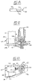
- first frame 8 There is a first frame 8, as perhaps shown most clearly in Figures 1, 2 and 5, attached to the harness.
- a second frame 10 is pivotally attached to the first frame 8.
- the second frame includes a main plate 12, disposable generally parallel to the back of the rider 4 when in use, as shown in Figure 1.
- first and second extensions 14 and 16 extending from the plate 12 to the first frame 8.
- Corresponding extensions 18 extend from the first frame 8 and there are pivoting connections between the extensions 18 of the first frame 8 and those of the second frame 10.
- the pivotal attachment of the second frame to the first is by an upper pin 20 and by a lower pin 22, received within housing 24 and shown in Figure 3. Housing 24, is attached to the upper extension 14 of the second frame 10.
- a locking pin 26 is mounted on the lower extension 16 of the second frame 10.
- a plurality of recesses 28 are formed in the first frame 8 - see Figure 3 - and the locking pin 26 can be engaged at the will of the rider in a recess 28 to control the trim of the device relative to, for example, wind direction.
- the locking pin 26 is movable by a flexible cable 30.
- the flexible cable 30 is mounted within a swing arm 32, attached to housing 24, and movable to suit the bicycle rider 4.
- Swing arm 32 is pivotally received within a bushing 33 - see Figure 3 - extending through housing 24 and allowing pivoting of arm 32 about a generally horizontal axis.
- Arm 32 extends from the pivotable joint in the lower extension 16 of the second frame outward and forward, as shown particularly in Figures 1 and 3, to the hand of the bicycle rider 4.
- a pivotable joint 34 is provided in the swing arm 32 to facilitate the positioning of the arm 32.
- arm 32 can pivot about the generally horizontal axis of bushing 33 and about the generally vertical axis of joint 34.
- the swing arm 32 may then be moved until the pin 26 aligns with another recess 28 in the first frame 8, the lever 36 is then released and the pin 26 engages in a different, recess 28.
- the pin 26 is spring-loaded to be urged towards an opening 28, that is downwardly in the drawings, so that release of the control lever 36 is sufficient to allow reengagement of the pin 26 in an opening 28.
- a sail 38 mounted on the second frame 10, movable between a retracted and extended position. This is made possible by the provision of masts 40 and 42, movable between a first position, close to each other, to a second position, remote from each other to retract and extend the sail. Such movement is accomplished by the provision of rotatable gears 44 mounted on the second frame 10. There are arms 46 extending from each gear and rotatable with the gears 44. The arrangement is illustrated in Figure 4 where the extended position for the sail is shown in solid lines and the retracted position in broken lines. For clarity in Figure 4 the sail is omitted.
- a drive shaft 48 mounted on the second frame 10 with drive gears 50, in the form of worm gears, to engage the rotatable gears 44.
- the arrangement is such that rotation of the drive shaft 48 rotates the worm gears 50, and thus the rotatable gears 44, to move the arms 46 from the broken line position in Figure 4 to the solid line position in Figure 4, thus extending the masts 40 and 42 and thus extending the sail.
- an electric motor 52 is mounted on the first extension 16 and is attached at gear box 54 to the drive shaft 48.
- a hand crank 55 is provided for rotation of the shaft 48, in particular for retraction of the sail 38, if the electric motor 52 fails.
- Operation of the electric motor is by a simple three position toggle switch 56 attached to the swing arm 32 as shown in Figure 3.
- the three positions for the switch 56 are extend, retract and off.
- Power for the electric motor may be provided by a battery mounted on the frame of the bicycle.
- the sail 38 is attached to one mast 40 but passes over the second mast 42 and is attached to a reefing mechanism that is attached to the second mast 42 to reef the sail 38 on its retraction.
- the masts 40 and 42 are desirably of aerodynamic configuration, having a rounded outer surface and tapering inwardly.
- the reefing mechanism is shown most clearly in Figures 6 and 7. It comprises a first tube 58 that is rotatable relative to the mast 42.
- Figure 6 shows only one end of the first tube 58 but, in fact, the other end of the tube 58 is precisely the same.
- a coil spring 60 is located within the first tube 58 and is anchored at its inner end by pin 62 that is fixed relative to the first tube 58 and must rotate with the first tube 58.
- the spring 60 is mounted on a pin 64, as shown particularly in Figure 7. The arrangement is such that rotation of the first tube 58 coils and uncoils the spring 60.
- a second tube 66 slidably located within the first tube 58 by bearing 68.
- the second tube 66 is also received within rose joint 70 that is attached to plate 72, in turn attached to the top of the mast 42.
- the outer end of the second tube 66 is slotted at 74 to receive the pin 64 for the coil spring 60.
- the pin 64 is attached to a U-bracket 76 that is anchored, for example in a spring clip 78, on the plate 72 on the mast 42.
- the U-bracket 76 can be removed from the clip 78, the second tube 66 rotated relative to the first 58 by turning U-bracket 76 to pretension the spring 60 and the bracket 76 then relocated within clip 78.
- limit switches are provided to stop the motor 52 when the masts reach their maximum outward extension and inward retraction.
- the harness is strapped to the back of the rider who mounts the bicycle.
- the rider may cycle along or may extend the sail at rest.
- switch 56 is operated to permit power to pass to the electric motor to extend the sails by rotating shaft 48.
- the trim of the sail can be adjusted by releasing lever 36, moving the swingarm 32 to control the trim of the sail, releasing the lever 32 so locking pin 26 may reengage in an opening 28 and fixing the relative position of the frames and thus the trim of the sail to the wind.
- the present invention thus provides an efficient means of facilitating bicycle travel.
- the mounting of the device on the back of the bicycle rider has been found to be of major significance.
- the rider, once skilled, can vary the inclination of the sail, simply by bending his back, and thus reduce the affects of gusting, which, in the inventor's experience, is not possible when the sail is mounted directly to the bicycle.
- FIGs 8, 9 and 10 illustrate a means of avoiding this problem.
- First Figure 8 simply shows the addition of a further switch 100 at forward end 37 of swing arm 32.
- Figures 9 and 10 show the provision of a solenoid 102 having connections 104 from a power supply and mounted on a plate 106 at the end of mast 42.
- Solenoid 102 has a shaft 108 that extends under the influence of an internal spring (not shown) when the solenoid is deenergized.
- an internal spring not shown
- Shaft 108 is fitted with a catch 110.
- Plate 106 is provided with a guide track 112 for the catch 110.
- catch 110 is of considerable height.
- a wheel 114 is attached to second tube 66 and is prevented from turning on the shaft by the provision of screws 116. As shown in Figure 10 the wheel 114 has a plurality of indents 118. A sprocket wheel is appropriate.
- the solenoid 102 does not interfere with the operation of the device.
- switch 56 is moved to the off position power is cut off from the solenoid 102 and catch 110 therefore moves outwardly, under the influence of the internal spring, to engage the wheel 114 to prevent rotation of the reefer mechanism. By this means the wind cannot extend the sail when the operator does not wish the sail to be extended.
- the illustrated catch 110 is relatively long. This is so that it can accommodate movement of the roller reefer. As indicated above the roller reefer moves during deployment and retraction and the long catch insures engagement with the wheel 114 anywhere on the travel of the rolier reefer.
- the guide 112 ensures that the catch will not rotate on the solenoid plunger 110 if the plunger well up on the catch.
Landscapes
- Engineering & Computer Science (AREA)
- Mechanical Engineering (AREA)
- Vehicle Interior And Exterior Ornaments, Soundproofing, And Insulation (AREA)
- Seal Device For Vehicle (AREA)
- Power Steering Mechanism (AREA)
- Toys (AREA)
- Steering Devices For Bicycles And Motorcycles (AREA)
- Wind Motors (AREA)
Claims (22)
Priority Applications (1)
| Application Number | Priority Date | Filing Date | Title |
|---|---|---|---|
| AT86307012T ATE43111T1 (de) | 1985-09-11 | 1986-09-11 | Segelvorrichtung. |
Applications Claiming Priority (2)
| Application Number | Priority Date | Filing Date | Title |
|---|---|---|---|
| US77494285A | 1985-09-11 | 1985-09-11 | |
| US774942 | 1985-09-11 |
Publications (2)
| Publication Number | Publication Date |
|---|---|
| EP0219970A1 EP0219970A1 (fr) | 1987-04-29 |
| EP0219970B1 true EP0219970B1 (fr) | 1989-05-17 |
Family
ID=25102783
Family Applications (1)
| Application Number | Title | Priority Date | Filing Date |
|---|---|---|---|
| EP86307012A Expired EP0219970B1 (fr) | 1985-09-11 | 1986-09-11 | Dispositif à voile |
Country Status (5)
| Country | Link |
|---|---|
| US (1) | US4738460A (fr) |
| EP (1) | EP0219970B1 (fr) |
| AT (1) | ATE43111T1 (fr) |
| AU (1) | AU590613B2 (fr) |
| DE (1) | DE3663356D1 (fr) |
Families Citing this family (6)
| Publication number | Priority date | Publication date | Assignee | Title |
|---|---|---|---|---|
| US5713603A (en) * | 1996-01-11 | 1998-02-03 | Carter; Robert L. | Body mounted sail assembly |
| US6234530B1 (en) * | 1998-09-30 | 2001-05-22 | Robert L. Carter | Body mounted sail assembly with safety features |
| USD613360S1 (en) * | 2008-08-18 | 2010-04-06 | Smith Iv Harry William | Multi-purpose body-sail with swallow tail |
| US8240714B2 (en) * | 2009-08-14 | 2012-08-14 | Lopez Jose A | Skateboard with sail assembly |
| US8162336B1 (en) | 2010-07-01 | 2012-04-24 | Gilman Loren L | Wind actuated bicycle sail |
| US8196684B2 (en) * | 2010-10-20 | 2012-06-12 | Caiozza Joseph C | Wearable folding wing apparatus |
Family Cites Families (16)
| Publication number | Priority date | Publication date | Assignee | Title |
|---|---|---|---|---|
| DE75187C (de) * | H. DE BU-COURT in Uerdingen a. Rhein, Mörserstr. 60 | Vorrichtung zum Verstellen von Segeln und Schirmen an Fahrrädern | ||
| DE102888C (fr) * | ||||
| US685943A (en) * | 1901-02-28 | 1901-11-05 | James P Pool | Sail-boat. |
| FR400800A (fr) * | 1909-03-12 | 1909-08-07 | Alfred Arthur Strachan | Serre-voiles économique et rapide |
| US1438246A (en) * | 1921-03-03 | 1922-12-12 | Carl W A Koelkebeck | Sailing vessel |
| US2018062A (en) * | 1935-06-03 | 1935-10-22 | Hardt Casper | Individual sail device |
| FR1499954A (fr) * | 1966-04-28 | 1967-11-03 | Article de sport et d'agrément comportant en combinaison des patins à roues et unevoile | |
| US3742886A (en) * | 1971-08-02 | 1973-07-03 | J Dillon | Catamaran |
| US3802371A (en) * | 1972-02-29 | 1974-04-09 | J Jastrab | Sailing rig |
| US3836176A (en) * | 1972-12-08 | 1974-09-17 | C Ylvisaker | Bicycle sail |
| US3994508A (en) * | 1975-04-11 | 1976-11-30 | Danner Carl L | Sail control apparatus for vehicles |
| DE2925378A1 (de) * | 1979-06-22 | 1981-01-15 | Anton Dipl Ing Piller | Segelgeraet, bestehend aus einem brett und einem segel |
| US4367688A (en) * | 1980-12-12 | 1983-01-11 | Godfrey Thomas B A | Sailboat rig |
| US4418632A (en) * | 1981-04-28 | 1983-12-06 | Nippon Kokan Kabushiki Kaisha | Method for operating a rigid marine sail |
| US4441728A (en) * | 1981-08-10 | 1984-04-10 | Schroeder Warren C | Bicycle sail |
| DE3316139A1 (de) * | 1983-05-03 | 1984-11-08 | Hartmut Berthold 2000 Norderstedt Schwarz | Segelschiff |
-
1986
- 1986-09-11 AT AT86307012T patent/ATE43111T1/de not_active IP Right Cessation
- 1986-09-11 AU AU62584/86A patent/AU590613B2/en not_active Ceased
- 1986-09-11 DE DE8686307012T patent/DE3663356D1/de not_active Expired
- 1986-09-11 EP EP86307012A patent/EP0219970B1/fr not_active Expired
-
1987
- 1987-02-24 US US07/017,907 patent/US4738460A/en not_active Expired - Fee Related
Also Published As
| Publication number | Publication date |
|---|---|
| EP0219970A1 (fr) | 1987-04-29 |
| AU6258486A (en) | 1987-03-12 |
| ATE43111T1 (de) | 1989-06-15 |
| DE3663356D1 (en) | 1989-06-22 |
| AU590613B2 (en) | 1989-11-09 |
| US4738460A (en) | 1988-04-19 |
Similar Documents
| Publication | Publication Date | Title |
|---|---|---|
| US5366182A (en) | Kiteski | |
| US6877697B2 (en) | Kite control systems | |
| US7294029B1 (en) | Mount apparatus for a trolling motor | |
| US6505573B1 (en) | Towrope retriever for watercraft | |
| US9180943B2 (en) | Water sports foldable towing apparatus and method | |
| EP0219970B1 (fr) | Dispositif à voile | |
| AU651552B2 (en) | Sail-wing and controls for a sail craft | |
| US9567072B2 (en) | Kite control bar with integrated line adjustment means | |
| US10407140B2 (en) | Paddleboard rudder control system | |
| US8082869B2 (en) | Anchor system for a kayak | |
| US3303813A (en) | Water ski launching system | |
| JPH0794235B2 (ja) | 舟艇とその駆動機構 | |
| EP1183083A1 (fr) | Commande du filin d'un cerf-volant comportant une fixation sur le corps | |
| KR20170090702A (ko) | 수상 웨이크 보드 | |
| US20080223989A1 (en) | Force Balancing Kite Control System | |
| TW202114907A (zh) | 具有升降機構之馬達總成及包含該總成之船舶 | |
| US4061101A (en) | Sail furling apparatus | |
| EP0229675B2 (fr) | Support pour voiles d'un bateau à voile | |
| US10336413B2 (en) | Kite control bar with integrated line adjustment means | |
| US4634136A (en) | Wind powered propulsion device | |
| CA1293749C (fr) | Dispositif propulseur faisant appel au vent | |
| US4190980A (en) | Model sailboat sheet winch | |
| US5676079A (en) | Reduced drag rudder for tiller steered sailboats | |
| US4515100A (en) | Attachment for sail vehicles to automatically compensate for varying wind pressure | |
| US3511208A (en) | Fishing rig |
Legal Events
| Date | Code | Title | Description |
|---|---|---|---|
| PUAI | Public reference made under article 153(3) epc to a published international application that has entered the european phase |
Free format text: ORIGINAL CODE: 0009012 |
|
| AK | Designated contracting states |
Kind code of ref document: A1 Designated state(s): AT BE CH DE FR GB IT LI LU NL SE |
|
| 17P | Request for examination filed |
Effective date: 19871021 |
|
| 17Q | First examination report despatched |
Effective date: 19880804 |
|
| GRAA | (expected) grant |
Free format text: ORIGINAL CODE: 0009210 |
|
| AK | Designated contracting states |
Kind code of ref document: B1 Designated state(s): AT BE CH DE FR GB IT LI LU NL SE |
|
| REF | Corresponds to: |
Ref document number: 43111 Country of ref document: AT Date of ref document: 19890615 Kind code of ref document: T |
|
| ITF | It: translation for a ep patent filed | ||
| REF | Corresponds to: |
Ref document number: 3663356 Country of ref document: DE Date of ref document: 19890622 |
|
| ET | Fr: translation filed | ||
| PLBE | No opposition filed within time limit |
Free format text: ORIGINAL CODE: 0009261 |
|
| STAA | Information on the status of an ep patent application or granted ep patent |
Free format text: STATUS: NO OPPOSITION FILED WITHIN TIME LIMIT |
|
| 26N | No opposition filed | ||
| ITTA | It: last paid annual fee | ||
| EPTA | Lu: last paid annual fee | ||
| PGFP | Annual fee paid to national office [announced via postgrant information from national office to epo] |
Ref country code: LU Payment date: 19940901 Year of fee payment: 9 |
|
| PGFP | Annual fee paid to national office [announced via postgrant information from national office to epo] |
Ref country code: GB Payment date: 19940909 Year of fee payment: 9 |
|
| PGFP | Annual fee paid to national office [announced via postgrant information from national office to epo] |
Ref country code: SE Payment date: 19940928 Year of fee payment: 9 Ref country code: AT Payment date: 19940928 Year of fee payment: 9 |
|
| PGFP | Annual fee paid to national office [announced via postgrant information from national office to epo] |
Ref country code: NL Payment date: 19940930 Year of fee payment: 9 Ref country code: FR Payment date: 19940930 Year of fee payment: 9 Ref country code: CH Payment date: 19940930 Year of fee payment: 9 |
|
| PGFP | Annual fee paid to national office [announced via postgrant information from national office to epo] |
Ref country code: BE Payment date: 19941011 Year of fee payment: 9 |
|
| PGFP | Annual fee paid to national office [announced via postgrant information from national office to epo] |
Ref country code: DE Payment date: 19941025 Year of fee payment: 9 |
|
| EAL | Se: european patent in force in sweden |
Ref document number: 86307012.4 |
|
| PG25 | Lapsed in a contracting state [announced via postgrant information from national office to epo] |
Ref country code: LU Free format text: LAPSE BECAUSE OF NON-PAYMENT OF DUE FEES Effective date: 19950911 Ref country code: GB Effective date: 19950911 Ref country code: AT Effective date: 19950911 |
|
| PG25 | Lapsed in a contracting state [announced via postgrant information from national office to epo] |
Ref country code: SE Effective date: 19950912 |
|
| PG25 | Lapsed in a contracting state [announced via postgrant information from national office to epo] |
Ref country code: LI Effective date: 19950930 Ref country code: CH Effective date: 19950930 Ref country code: BE Effective date: 19950930 |
|
| BERE | Be: lapsed |
Owner name: ALEXANDER LINC W. Effective date: 19950930 |
|
| PG25 | Lapsed in a contracting state [announced via postgrant information from national office to epo] |
Ref country code: NL Effective date: 19960401 |
|
| GBPC | Gb: european patent ceased through non-payment of renewal fee |
Effective date: 19950911 |
|
| REG | Reference to a national code |
Ref country code: CH Ref legal event code: PL |
|
| PG25 | Lapsed in a contracting state [announced via postgrant information from national office to epo] |
Ref country code: FR Effective date: 19960531 |
|
| PG25 | Lapsed in a contracting state [announced via postgrant information from national office to epo] |
Ref country code: DE Effective date: 19960601 |
|
| NLV4 | Nl: lapsed or anulled due to non-payment of the annual fee |
Effective date: 19960401 |
|
| EUG | Se: european patent has lapsed |
Ref document number: 86307012.4 |
|
| REG | Reference to a national code |
Ref country code: FR Ref legal event code: ST |
|
| PG25 | Lapsed in a contracting state [announced via postgrant information from national office to epo] |
Ref country code: IT Free format text: LAPSE BECAUSE OF NON-PAYMENT OF DUE FEES Effective date: 20050911 |