EP0220068A2 - Fahrzeugscheinwerfer - Google Patents
Fahrzeugscheinwerfer Download PDFInfo
- Publication number
- EP0220068A2 EP0220068A2 EP86308070A EP86308070A EP0220068A2 EP 0220068 A2 EP0220068 A2 EP 0220068A2 EP 86308070 A EP86308070 A EP 86308070A EP 86308070 A EP86308070 A EP 86308070A EP 0220068 A2 EP0220068 A2 EP 0220068A2
- Authority
- EP
- European Patent Office
- Prior art keywords
- rotation
- headlight
- actuator
- headlight unit
- light source
- Prior art date
- Legal status (The legal status is an assumption and is not a legal conclusion. Google has not performed a legal analysis and makes no representation as to the accuracy of the status listed.)
- Granted
Links
Images

Classifications
-
- F—MECHANICAL ENGINEERING; LIGHTING; HEATING; WEAPONS; BLASTING
- F21—LIGHTING
- F21S—NON-PORTABLE LIGHTING DEVICES; SYSTEMS THEREOF; VEHICLE LIGHTING DEVICES SPECIALLY ADAPTED FOR VEHICLE EXTERIORS
- F21S41/00—Illuminating devices specially adapted for vehicle exteriors, e.g. headlamps
- F21S41/60—Illuminating devices specially adapted for vehicle exteriors, e.g. headlamps characterised by a variable light distribution
- F21S41/67—Illuminating devices specially adapted for vehicle exteriors, e.g. headlamps characterised by a variable light distribution by acting on reflectors
- F21S41/675—Illuminating devices specially adapted for vehicle exteriors, e.g. headlamps characterised by a variable light distribution by acting on reflectors by moving reflectors
Definitions
- This invention relates to a headlight unit, and in particularly to a headlight unit for motor vehicles, such as cars, in which the high beam and the low beam are obtained by rotating a reflecting mirror.
- One of these uses a sealed beam type lamp in which two light sources are provided in conjunction with a reflecting mirror. When one of these light sources is operated, the low beam is generated, and when the other light source is operated or both light sources are operated at the same time, the high beam is generated. In this type lamp the beams are switched by switching the light sources.
- one light source is used with a reflecting mirror.
- the beam is switched by rotating or tilting the reflecting mirror or the light source, itself, upward and downward.
- This invention relates to the latter system, the problems of which are discussed below.
- the downward attitude of the reflecting mirror when the low beam is lit must be controlled with great accuracy to avoid blinding oncoming traffic.
- a vertical aiming bolt and a surrounding coil spring have been used to control the attitude of the reflecting mirror in the vertical direction.
- This bolt acts as a stopper, which controls the downward attitude position of the reflecting mirror.
- the spring is designed to permit the rotation of the reflecting mirror to allow upward rotation.
- an actuator is used to make the reflecting mirror rotate upward and downward. Hitherto, solenoid systems, compressed gas systems, or motor drive systems have been used as actuators.
- a headlight system which uses this kind of actuator with a vertical direction aiming bolt controls the downward attitude position of the reflecting mirror through the vertical aiming bolt, and determines the high beam direction by rotation of the reflecting mirror upward in response to the working stroke of the actuator.
- the position for the downward attitude of the reflecting mirror is determined by adjusting the vertical direction aiming bolt. Then, the upward position is adjusted by operating the actuator.
- the present invention seeks to provide a headlight unit of a simpler construction in which vertical aiming adjustments of the reflecting mirror and rotational adjustments of the reflecting mirror can be easily carried out and, at the same time, the need for a vertical aiming bolt and spring can be eliminated.
- the invention seeks to simplify the adjustment of a headlight unit having a movable reflector, and to reduce the number of parts of an adjustable headlight unit.
- a headlight unit comprises: a light source; reflector means for reflecting the light from the light source into a beam; and circuit means characterised in that the circuit means adjusts the position of the beam and controls the degree of rotation of the reflecting means.
- a headlight unit comprises: a light source; reflector means for reflecting light from the light source into a beam; and an actuator for adjusting the orientation of the reflector means, characterised by circuit means for determining the degree of adjustment of orientation of the reflector means and for controlling the actuator accordingly and thereby adjusting the direction of the beam.
- the headlight unit may have a motor with an adjustable angle of rotation, for example a servo-motor or a stepping motor, as the actuator, and a controller to control this motor.
- this controller can be designed to control the vertical aiming position of the headlight by controlling the angle of rotation of the motor, and to adjust the aiming position of the headlight beam.
- a housing 1 is secured to a car body (not shown).
- a transparent cover 2 transmits the beam projected from a headlight 3 in the forward direction and plays the role of the front lens.
- Headlight 3 is housed in the space enclosed by housing 1 and transparent cover 2.
- Headlight 3 is constructed by housing a light source, for instance a small metal vapour discharge lamp 5, in a reflecting mirror 4.
- Reflecting mirror 4 is formed of a metal with high reflectivity, such as bright aluminium.
- Reflecting mirror 4 is supported on housing 1 by center pivot 6 and left/right directional aiming bolt 7.
- brackets 8 and 9 are connected to the back of reflecting mirror 4.
- a rod 10 which supports center pivot 6 is secured to housing 1.
- Left/right directional aiming bolt 7 is inserted through housing 1.
- bracket 8 is connected to rod 10 of center pivot 6 through ball joint 11, which is free to rotate.
- left/right directional aiming bolt 7 is inserted through bracket 9.
- a nut 12, a spring washer 13 and a spring 14 are fitted to this left/right directional aiming bolt 7.
- This bracket 9 can be altered by adjusting the position of nut 12. By this position change, it becomes possible for reflecting mirror 4 to rotate to the left or right (in the directions of arrow A in Figure 2) about ball joint 11. Therefore, the left/right direction of reflecting mirror 4 (in the directions of arrow A in Figure 2) can be adjusted by left/right directional aiming bolt 7. Moreover, reflecting mirror 4 is supported in such a way that its front opening is capable of rotating upward and downward about the line P - P (shown by point P in Figure 1) drawn between ball joint 11 of center pivot 6 and nut 12 of left/right directional aiming bolt 7.
- This type of reflecting mirror 4 is rotated upward and downward by actuator 15, which is fitted in the bottom of housing 1.
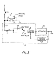
- Actuator 15 is, for example, composed of a direct current type servo-motor. The angle of rotation of this motor is controlled by controller 16 shown in Figure 3.
- Controller 16 is constructed as follows.
- Numeral 17 designates an encoder
- numeral 18 designates an adder
- numeral 19 designates a high beam/low beam changeover switch.
- The'numeral 20 designates an adjuster to adjust the amount of vertical rotation ⁇ of the headlight, and is composed of variable resistors, etc.
- the numeral 21 designates an adjuster for adjusting the vertical aiming and is also composed of variable resistors, etc.
- the numeral 22 designates an auxiliary resistor.
- Controller 16 constructed in this way is connected to the headlight main switch 23.
- Headlight main switch 23 is connected to a small metal-vapour discharge lamp 5, which is the light source, and to the lighting circuit 24.
- a rubber cover 25 covers the open section at the back of housing 1 and insulates the supply terminals of small metal-vapour discharge lamp 5. Rubber cover 25 permits the movement of small metal-vapour discharge lamp 5 when reflecting mirror 4 is rotated upward or downward. Moreover, a water drain hole 26 is formed in this rubber cover 25. Water drain hole 26 allows water to drain out when it has penetrated the upper part of reflecting mirror 4.
- small metal-vapour discharge lamp 5 which is the light source
- headlight main switch 23 When small metal-vapour discharge lamp 5, which is the light source, is lit by closing headlight main switch 23, the light emitted from this light source is reflected by reflecting mirror 4 and is projected forward as a beam. This beam passes through transparent cover 2 and illuminates the road surface ahead.
- headlight 3 rotates about center-line of rotation P - P and the axis of the beam can be rotated upward or downward between the lines 0 1 - 0 1 and 0 - 0 2 , as shown in Figure 1.
- the amount of rotation ⁇ of headlight 3 and the vertical aiming position can be adjusted by servo-motor 15, which acts as the actuator.
- servo-motor 15 acts as the actuator.
- the amount of rotation of servo-motor 15 is determined according to the value of this resistance (according to the voltage level).
- This amount of rotation of servo-motor 15 determines the direction of upward beam 0 1 - 0 1 by rotating headlight 3. Thus, it determines the vertical aiming position.
- encoder 17 and adder 18 control the angle of rotation of servo-motor 15 in response to the voltage level amount reduced by the resistance of vertical aiming adjuster 21. Headlight 3 is rotated upward by this angle of rotation of servo-motor 15, so that upward beam 0 - 0 1 is projected.
- encoder 17 and adder 18 control the angle of rotation of servo-motor 15 in response to the voltage level amount, reduced by the sum of the resistance of vertical aiming adjuster 21 and the resistance of rotation amount adjuster 20. Headlight 3 is rotated downward by this angle of rotation of servo-motor 15, so that downward beam 0 2 - 0 2 is projected.
- a servo-motor is used to control the angle of rotation
- a magnetic system or a compressed gas system with an adjustable angle of rotation could be used as the actuator.
- the position of installation of the actuator is not confined to the lower part of the headlight. It also could be installed in the upper part or rear part of the headlight.
- this invention is not restricted to the use of small metal-vapour discharge lamps as light sources. Incandescent bulbs, such as halogen bulbs, also could be used.
- This invention is capable of use with, for example, sealed beam lamps, etc, when lamps housing single light sources and their envelopes are operated together by actuators.
- the amount of vertical rotation of the headlight is also adjusted by using a motor which can control the angle of rotation as the actuator and controlling this motor by a controller, the conventional vertical aiming bolt and spring can be eliminated.
- adjustment of the vertical position determination and adjustment of the amount of rotation of the reflecting mirror can be carried out independently from each other or in succession using a single motor. Also, the work of adjustment is simple, since even if one is adjusted there is no need to readjust the other.
Landscapes
- Engineering & Computer Science (AREA)
- General Engineering & Computer Science (AREA)
- Lighting Device Outwards From Vehicle And Optical Signal (AREA)
- Non-Portable Lighting Devices Or Systems Thereof (AREA)
Applications Claiming Priority (2)
| Application Number | Priority Date | Filing Date | Title |
|---|---|---|---|
| JP60233074A JPS6293802A (ja) | 1985-10-18 | 1985-10-18 | 車両用前照灯 |
| JP233074/85 | 1985-10-18 |
Publications (3)
| Publication Number | Publication Date |
|---|---|
| EP0220068A2 true EP0220068A2 (de) | 1987-04-29 |
| EP0220068A3 EP0220068A3 (en) | 1988-11-09 |
| EP0220068B1 EP0220068B1 (de) | 1992-03-25 |
Family
ID=16949394
Family Applications (1)
| Application Number | Title | Priority Date | Filing Date |
|---|---|---|---|
| EP86308070A Expired - Lifetime EP0220068B1 (de) | 1985-10-18 | 1986-10-17 | Fahrzeugscheinwerfer |
Country Status (5)
| Country | Link |
|---|---|
| US (1) | US4739223A (de) |
| EP (1) | EP0220068B1 (de) |
| JP (1) | JPS6293802A (de) |
| CA (1) | CA1289118C (de) |
| DE (1) | DE3684550D1 (de) |
Cited By (1)
| Publication number | Priority date | Publication date | Assignee | Title |
|---|---|---|---|---|
| EP0705730A3 (de) * | 1994-10-04 | 1996-10-02 | Bosch Gmbh Robert | Scheinwerfer für Abblendlicht und Fernlicht für Fahrzeuge |
Families Citing this family (9)
| Publication number | Priority date | Publication date | Assignee | Title |
|---|---|---|---|---|
| IT1210733B (it) * | 1987-05-13 | 1989-09-20 | Paolo Soardo | Programmabile proiettore per autoveicoli con ripartizione luminosa |
| JP2691945B2 (ja) * | 1990-05-18 | 1997-12-17 | 株式会社小糸製作所 | 車輌用前照灯 |
| US5633710A (en) * | 1995-10-04 | 1997-05-27 | Egs Inc. | System for self-aligning vehicle headlamps |
| FR2745061B1 (fr) * | 1996-02-20 | 1998-05-07 | Valeo Vision | Projecteur de vehicule automobile, comportant une source lumineuse unique et susceptible d'emettre un faisceau de croisement et un faisceau de route |
| US8251558B1 (en) * | 2009-08-06 | 2012-08-28 | Ibis Tek, Llc | Headlamp system and kit providing on-road and off-road illumination |
| US8496365B2 (en) | 2010-12-08 | 2013-07-30 | Ford Global Technologies, Llc | Articulating lamp assembly for a vehicle |
| US8475022B2 (en) | 2010-12-08 | 2013-07-02 | Ford Global Technologies, Llc | Articulating reflector lighting assembly for a vehicle |
| JP2012204313A (ja) * | 2011-03-28 | 2012-10-22 | Stanley Electric Co Ltd | 車両用灯具のレンズカバー |
| US9534759B2 (en) * | 2014-03-14 | 2017-01-03 | Ford Global Technologies, Llc | Lamp adjuster to control margins |
Family Cites Families (13)
| Publication number | Priority date | Publication date | Assignee | Title |
|---|---|---|---|---|
| US1259252A (en) * | 1917-03-12 | 1918-03-12 | Joseph Mccaskey | Automobile-light. |
| US1819690A (en) * | 1929-04-26 | 1931-08-18 | Chester S Ricker | Head lamp control |
| US3079529A (en) * | 1958-12-24 | 1963-02-26 | Harrv E Novinger | Automobile headlight |
| DE1772526C3 (de) * | 1968-05-30 | 1975-12-04 | Robert Bosch Gmbh, 7000 Stuttgart | Abblendschalteinrichtung für Scheinwerfer |
| JPS477746A (de) * | 1970-09-30 | 1972-04-25 | ||
| DE2639263A1 (de) * | 1976-09-01 | 1978-03-02 | Bosch Gmbh Robert | Steuerbare scheinwerferanlage fuer kraftfahrzeuge |
| DE2639720C2 (de) * | 1976-09-03 | 1987-03-26 | Robert Bosch Gmbh, 7000 Stuttgart | Regeleinrichtung für Kraftfahrzeug-Scheinwerfer |
| FR2384654A1 (fr) * | 1977-03-25 | 1978-10-20 | Cibie Projecteurs | Dispositif pour la commande conjointe de l'inclinaison des projecteurs d'un vehicule automobile |
| US4363085A (en) * | 1980-05-05 | 1982-12-07 | Edison International, Inc. | Scan synthesized beam headlamp |
| US4513357A (en) * | 1983-01-19 | 1985-04-23 | Tokyo Shibaura Denki Kabushiki Kaisha | Headlamp unit with timed switching between two lights |
| DE3467990D1 (en) * | 1983-03-22 | 1988-01-21 | Ichikoh Industries Ltd | Device for adjusting the inclination of the light axis of headlamps of a motor vehicle |
| EP0138217B1 (de) * | 1983-10-14 | 1988-01-27 | Ichikoh Industries Limited | Vorrichtung zur Einstellung von Scheinwerfern eines Fahrzeuges |
| FR2574725B1 (fr) * | 1984-12-14 | 1987-03-20 | Cibie Projecteurs | Correcteur automatique de la direction des projecteurs lors des variations d'assiette d'un vehicule |
-
1985
- 1985-10-18 JP JP60233074A patent/JPS6293802A/ja active Pending
-
1986
- 1986-10-16 US US06/919,504 patent/US4739223A/en not_active Expired - Lifetime
- 1986-10-17 CA CA000520820A patent/CA1289118C/en not_active Expired - Lifetime
- 1986-10-17 DE DE8686308070T patent/DE3684550D1/de not_active Expired - Lifetime
- 1986-10-17 EP EP86308070A patent/EP0220068B1/de not_active Expired - Lifetime
Cited By (2)
| Publication number | Priority date | Publication date | Assignee | Title |
|---|---|---|---|---|
| EP0705730A3 (de) * | 1994-10-04 | 1996-10-02 | Bosch Gmbh Robert | Scheinwerfer für Abblendlicht und Fernlicht für Fahrzeuge |
| US5769525A (en) * | 1994-10-04 | 1998-06-23 | Robert Bosch Gmbh | Low/high beam headlight for vehicles |
Also Published As
| Publication number | Publication date |
|---|---|
| US4739223A (en) | 1988-04-19 |
| CA1289118C (en) | 1991-09-17 |
| EP0220068A3 (en) | 1988-11-09 |
| JPS6293802A (ja) | 1987-04-30 |
| DE3684550D1 (de) | 1992-04-30 |
| EP0220068B1 (de) | 1992-03-25 |
Similar Documents
| Publication | Publication Date | Title |
|---|---|---|
| US6953274B2 (en) | AFS for LED headlamp | |
| US6848814B2 (en) | Vehicle headlamp | |
| US7201505B2 (en) | Projector type vehicle headlamp | |
| EP1772311B1 (de) | Fahrzeugscheinwerfer | |
| US6623147B2 (en) | Vehicle lighting apparatus | |
| US7815352B2 (en) | Vehicular headlamp | |
| US20010040810A1 (en) | Vehicle headlamp | |
| JP3943261B2 (ja) | 車両用前照灯 | |
| US6527424B2 (en) | Headlight for vehicle for producing a low beam and at least one light beam with greater range with safety device for monitoring adjustment of relative position between light source and reflector | |
| GB2380252A (en) | Headlamp device for a vehicle | |
| US4739223A (en) | Headlight unit | |
| US4675793A (en) | Adjustable headlight | |
| EP2154426A2 (de) | Fahrzeugscheinwerfer | |
| US6238071B1 (en) | Motor vehicle headlight having a single light source and adapted to produce a dipped beam and a main beam | |
| GB2387899A (en) | Headlamp with movable condenser lens | |
| US6513958B2 (en) | Vehicle lamp system | |
| US6152584A (en) | Vehicle headlight | |
| US5785405A (en) | Device for adjusting a presettable lighting level of a headlight in motor vehicles | |
| GB2367122A (en) | Anti-Dazzle Headlamp for a Motor Vehicle | |
| US6547429B2 (en) | Bi-functional tilted axis reflector headlamp | |
| KR0182211B1 (ko) | 자동차 헤드 램프 빔의 기울기 자동 조절 장치 | |
| JPH10208510A (ja) | 車両用前照灯 | |
| EP3995360B1 (de) | Fahrzeugleuchte | |
| JP3122035B2 (ja) | 車輌用前照灯 | |
| EP1155908A1 (de) | Scheinwerfer für ein Kraftfahrzeug |
Legal Events
| Date | Code | Title | Description |
|---|---|---|---|
| PUAI | Public reference made under article 153(3) epc to a published international application that has entered the european phase |
Free format text: ORIGINAL CODE: 0009012 |
|
| 17P | Request for examination filed |
Effective date: 19861031 |
|
| AK | Designated contracting states |
Kind code of ref document: A2 Designated state(s): DE FR GB IT NL SE |
|
| PUAL | Search report despatched |
Free format text: ORIGINAL CODE: 0009013 |
|
| AK | Designated contracting states |
Kind code of ref document: A3 Designated state(s): DE FR GB IT NL SE |
|
| 17Q | First examination report despatched |
Effective date: 19901127 |
|
| GRAA | (expected) grant |
Free format text: ORIGINAL CODE: 0009210 |
|
| AK | Designated contracting states |
Kind code of ref document: B1 Designated state(s): DE FR GB IT NL SE |
|
| ET | Fr: translation filed | ||
| REF | Corresponds to: |
Ref document number: 3684550 Country of ref document: DE Date of ref document: 19920430 |
|
| ITF | It: translation for a ep patent filed | ||
| PLBE | No opposition filed within time limit |
Free format text: ORIGINAL CODE: 0009261 |
|
| STAA | Information on the status of an ep patent application or granted ep patent |
Free format text: STATUS: NO OPPOSITION FILED WITHIN TIME LIMIT |
|
| PGFP | Annual fee paid to national office [announced via postgrant information from national office to epo] |
Ref country code: LU Payment date: 19930217 Year of fee payment: 8 |
|
| 26N | No opposition filed | ||
| EPTA | Lu: last paid annual fee | ||
| PGFP | Annual fee paid to national office [announced via postgrant information from national office to epo] |
Ref country code: GB Payment date: 19931007 Year of fee payment: 8 |
|
| PGFP | Annual fee paid to national office [announced via postgrant information from national office to epo] |
Ref country code: FR Payment date: 19931011 Year of fee payment: 8 Ref country code: DE Payment date: 19931011 Year of fee payment: 8 |
|
| PGFP | Annual fee paid to national office [announced via postgrant information from national office to epo] |
Ref country code: SE Payment date: 19931015 Year of fee payment: 8 |
|
| PGFP | Annual fee paid to national office [announced via postgrant information from national office to epo] |
Ref country code: NL Payment date: 19931031 Year of fee payment: 8 |
|
| PG25 | Lapsed in a contracting state [announced via postgrant information from national office to epo] |
Ref country code: GB Effective date: 19941017 |
|
| PG25 | Lapsed in a contracting state [announced via postgrant information from national office to epo] |
Ref country code: SE Effective date: 19941018 |
|
| EAL | Se: european patent in force in sweden |
Ref document number: 86308070.1 |
|
| PG25 | Lapsed in a contracting state [announced via postgrant information from national office to epo] |
Ref country code: NL Effective date: 19950501 |
|
| GBPC | Gb: european patent ceased through non-payment of renewal fee |
Effective date: 19941017 |
|
| NLV4 | Nl: lapsed or anulled due to non-payment of the annual fee | ||
| PG25 | Lapsed in a contracting state [announced via postgrant information from national office to epo] |
Ref country code: FR Effective date: 19950630 |
|
| PG25 | Lapsed in a contracting state [announced via postgrant information from national office to epo] |
Ref country code: DE Effective date: 19950701 |
|
| EUG | Se: european patent has lapsed |
Ref document number: 86308070.1 |
|
| REG | Reference to a national code |
Ref country code: FR Ref legal event code: ST |
|
| PG25 | Lapsed in a contracting state [announced via postgrant information from national office to epo] |
Ref country code: IT Free format text: LAPSE BECAUSE OF NON-PAYMENT OF DUE FEES;WARNING: LAPSES OF ITALIAN PATENTS WITH EFFECTIVE DATE BEFORE 2007 MAY HAVE OCCURRED AT ANY TIME BEFORE 2007. THE CORRECT EFFECTIVE DATE MAY BE DIFFERENT FROM THE ONE RECORDED. Effective date: 20051017 |