EP0220146A1 - Gasflaschenventile - Google Patents
Gasflaschenventile Download PDFInfo
- Publication number
- EP0220146A1 EP0220146A1 EP86850338A EP86850338A EP0220146A1 EP 0220146 A1 EP0220146 A1 EP 0220146A1 EP 86850338 A EP86850338 A EP 86850338A EP 86850338 A EP86850338 A EP 86850338A EP 0220146 A1 EP0220146 A1 EP 0220146A1
- Authority
- EP
- European Patent Office
- Prior art keywords
- valve
- gas
- sleeve
- gap
- sealing member
- Prior art date
- Legal status (The legal status is an assumption and is not a legal conclusion. Google has not performed a legal analysis and makes no representation as to the accuracy of the status listed.)
- Granted
Links
- 239000007789 gas Substances 0.000 claims abstract description 66
- 238000007789 sealing Methods 0.000 claims abstract description 21
- 230000033001 locomotion Effects 0.000 claims abstract description 11
- MYMOFIZGZYHOMD-UHFFFAOYSA-N Dioxygen Chemical compound O=O MYMOFIZGZYHOMD-UHFFFAOYSA-N 0.000 claims abstract description 4
- 229910001882 dioxygen Inorganic materials 0.000 claims abstract description 4
- 230000000630 rising effect Effects 0.000 claims description 11
- 239000000463 material Substances 0.000 claims description 6
- 230000006835 compression Effects 0.000 description 6
- 238000007906 compression Methods 0.000 description 6
- QVGXLLKOCUKJST-UHFFFAOYSA-N atomic oxygen Chemical compound [O] QVGXLLKOCUKJST-UHFFFAOYSA-N 0.000 description 5
- 239000001301 oxygen Substances 0.000 description 5
- 229910052760 oxygen Inorganic materials 0.000 description 5
- 239000000306 component Substances 0.000 description 3
- 238000010586 diagram Methods 0.000 description 3
- 239000003795 chemical substances by application Substances 0.000 description 2
- 239000000446 fuel Substances 0.000 description 2
- 230000003647 oxidation Effects 0.000 description 2
- 238000007254 oxidation reaction Methods 0.000 description 2
- 229910001369 Brass Inorganic materials 0.000 description 1
- 239000010951 brass Substances 0.000 description 1
- 230000004048 modification Effects 0.000 description 1
- 238000012986 modification Methods 0.000 description 1
Images


Classifications
-
- F—MECHANICAL ENGINEERING; LIGHTING; HEATING; WEAPONS; BLASTING
- F16—ENGINEERING ELEMENTS AND UNITS; GENERAL MEASURES FOR PRODUCING AND MAINTAINING EFFECTIVE FUNCTIONING OF MACHINES OR INSTALLATIONS; THERMAL INSULATION IN GENERAL
- F16K—VALVES; TAPS; COCKS; ACTUATING-FLOATS; DEVICES FOR VENTING OR AERATING
- F16K1/00—Lift valves or globe valves, i.e. cut-off apparatus with closure members having at least a component of their opening and closing motion perpendicular to the closing faces
- F16K1/30—Lift valves or globe valves, i.e. cut-off apparatus with closure members having at least a component of their opening and closing motion perpendicular to the closing faces specially adapted for pressure containers
- F16K1/301—Lift valves or globe valves, i.e. cut-off apparatus with closure members having at least a component of their opening and closing motion perpendicular to the closing faces specially adapted for pressure containers only shut-off valves, i.e. valves without additional means
- F16K1/302—Lift valves or globe valves, i.e. cut-off apparatus with closure members having at least a component of their opening and closing motion perpendicular to the closing faces specially adapted for pressure containers only shut-off valves, i.e. valves without additional means with valve member and actuator on the same side of the seat
-
- F—MECHANICAL ENGINEERING; LIGHTING; HEATING; WEAPONS; BLASTING
- F17—STORING OR DISTRIBUTING GASES OR LIQUIDS
- F17C—VESSELS FOR CONTAINING OR STORING COMPRESSED, LIQUEFIED OR SOLIDIFIED GASES; FIXED-CAPACITY GAS-HOLDERS; FILLING VESSELS WITH, OR DISCHARGING FROM VESSELS, COMPRESSED, LIQUEFIED, OR SOLIDIFIED GASES
- F17C13/00—Details of vessels or of the filling or discharging of vessels
- F17C13/04—Arrangement or mounting of valves
-
- F—MECHANICAL ENGINEERING; LIGHTING; HEATING; WEAPONS; BLASTING
- F17—STORING OR DISTRIBUTING GASES OR LIQUIDS
- F17C—VESSELS FOR CONTAINING OR STORING COMPRESSED, LIQUEFIED OR SOLIDIFIED GASES; FIXED-CAPACITY GAS-HOLDERS; FILLING VESSELS WITH, OR DISCHARGING FROM VESSELS, COMPRESSED, LIQUEFIED, OR SOLIDIFIED GASES
- F17C2205/00—Vessel construction, in particular mounting arrangements, attachments or identifications means
- F17C2205/03—Fluid connections, filters, valves, closure means or other attachments
- F17C2205/0302—Fittings, valves, filters, or components in connection with the gas storage device
- F17C2205/0323—Valves
- F17C2205/0329—Valves manually actuated
-
- F—MECHANICAL ENGINEERING; LIGHTING; HEATING; WEAPONS; BLASTING
- F17—STORING OR DISTRIBUTING GASES OR LIQUIDS
- F17C—VESSELS FOR CONTAINING OR STORING COMPRESSED, LIQUEFIED OR SOLIDIFIED GASES; FIXED-CAPACITY GAS-HOLDERS; FILLING VESSELS WITH, OR DISCHARGING FROM VESSELS, COMPRESSED, LIQUEFIED, OR SOLIDIFIED GASES
- F17C2205/00—Vessel construction, in particular mounting arrangements, attachments or identifications means
- F17C2205/03—Fluid connections, filters, valves, closure means or other attachments
- F17C2205/0302—Fittings, valves, filters, or components in connection with the gas storage device
- F17C2205/0382—Constructional details of valves, regulators
-
- F—MECHANICAL ENGINEERING; LIGHTING; HEATING; WEAPONS; BLASTING
- F17—STORING OR DISTRIBUTING GASES OR LIQUIDS
- F17C—VESSELS FOR CONTAINING OR STORING COMPRESSED, LIQUEFIED OR SOLIDIFIED GASES; FIXED-CAPACITY GAS-HOLDERS; FILLING VESSELS WITH, OR DISCHARGING FROM VESSELS, COMPRESSED, LIQUEFIED, OR SOLIDIFIED GASES
- F17C2205/00—Vessel construction, in particular mounting arrangements, attachments or identifications means
- F17C2205/03—Fluid connections, filters, valves, closure means or other attachments
- F17C2205/0388—Arrangement of valves, regulators, filters
- F17C2205/0394—Arrangement of valves, regulators, filters in direct contact with the pressure vessel
-
- F—MECHANICAL ENGINEERING; LIGHTING; HEATING; WEAPONS; BLASTING
- F17—STORING OR DISTRIBUTING GASES OR LIQUIDS
- F17C—VESSELS FOR CONTAINING OR STORING COMPRESSED, LIQUEFIED OR SOLIDIFIED GASES; FIXED-CAPACITY GAS-HOLDERS; FILLING VESSELS WITH, OR DISCHARGING FROM VESSELS, COMPRESSED, LIQUEFIED, OR SOLIDIFIED GASES
- F17C2221/00—Handled fluid, in particular type of fluid
- F17C2221/01—Pure fluids
- F17C2221/011—Oxygen
-
- F—MECHANICAL ENGINEERING; LIGHTING; HEATING; WEAPONS; BLASTING
- F17—STORING OR DISTRIBUTING GASES OR LIQUIDS
- F17C—VESSELS FOR CONTAINING OR STORING COMPRESSED, LIQUEFIED OR SOLIDIFIED GASES; FIXED-CAPACITY GAS-HOLDERS; FILLING VESSELS WITH, OR DISCHARGING FROM VESSELS, COMPRESSED, LIQUEFIED, OR SOLIDIFIED GASES
- F17C2223/00—Handled fluid before transfer, i.e. state of fluid when stored in the vessel or before transfer from the vessel
- F17C2223/01—Handled fluid before transfer, i.e. state of fluid when stored in the vessel or before transfer from the vessel characterised by the phase
- F17C2223/0107—Single phase
- F17C2223/0123—Single phase gaseous, e.g. CNG, GNC
-
- F—MECHANICAL ENGINEERING; LIGHTING; HEATING; WEAPONS; BLASTING
- F17—STORING OR DISTRIBUTING GASES OR LIQUIDS
- F17C—VESSELS FOR CONTAINING OR STORING COMPRESSED, LIQUEFIED OR SOLIDIFIED GASES; FIXED-CAPACITY GAS-HOLDERS; FILLING VESSELS WITH, OR DISCHARGING FROM VESSELS, COMPRESSED, LIQUEFIED, OR SOLIDIFIED GASES
- F17C2223/00—Handled fluid before transfer, i.e. state of fluid when stored in the vessel or before transfer from the vessel
- F17C2223/03—Handled fluid before transfer, i.e. state of fluid when stored in the vessel or before transfer from the vessel characterised by the pressure level
- F17C2223/036—Very high pressure (>80 bar)
Definitions
- the present invention relates to an improved arrangement in valves for high-pressure gas cylinders, primarily oxygen gas cylinders, in order, during the opening phase of the valve, to prevent gas-rush - or as popularly entitled "gas hammer" - through the valve, the valve in the arrangement according to the present invention including an inlet connection intended to be screwed into the gas cylinder and containing an inlet passage for the gas.
- the object of the present invention is to realise an arrangement in the valve which prevents gas-rush through the valve and, as a result, the rapid compression of the gas.
- the present invention is, here, essentially characterised in that a tubular sleeve member is disposed in the gas passage of the valve connected to the gas cylinder, the sleeve member being axially movable a predetermined distance, and one end of the sleeve member abutting, when the valve is closed, against the movable sealing member of the valve, and the other end of the sleeve member abutting against spring means disposed in the gas passage, the diameter of the sleeve being such that a gap is created between the sleeve and the wall of the gas passage, the sleeve, during the initial phase of the opening movement of the valve spindle, abutting against the movable sealing member along the above-mentioned distance such that a minor volume of gas will flow through the
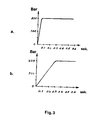
- the invention is further characterised in that the gap width and gap length are dimensioned such that, in the above-mentioned initial phase, the rising time of the gas flow to maximum flow is of such duration that the gas compressed in the valve housing during the rising time of the gas flow will attain a temperature which is lower than the threshold ignition temperature of the valve material.
- Fig. 1 shows a cylinder valve.
- This comprises an inlet connection 1 intended to be screwed into a gas cylinder, and an outlet connection 2 intended for connection to an outlet conduit.
- Gas from the cylinder passes through the gas passage 3 and, if the valve is open, past the valve seat 4 and out through the channel in the outlet connection 2.
- the valve is closed by turning the valve knob, in which event the movable sealing member 5 is, by means of the operating mechanism of the valve (in the illustrated embodiment a spindle and ball), urged against the seat 4 and thereby closes the gas passage 3.
- the movable sealing member 5 is, thus, lifted from the valve seat 4.
- Fig. 2 illustrates the outlet connection 1 and the lower portion of the movable sealing member 5 when the valve is opened and when the valve is closed, in each half of the Drawing, respectively.
- Bores 14 and 15 are provided in the gas passage 3 in the outlet connection.
- a sleeve-shaped member 6 is disposed in the gas passage most proximal the valve seat 4. This member is provided with a flange 7 at its end facing away from the valve seat. The flange is provided with one or more apertures 9.
- a spring 10 is disposed in the bore 15 in the gas passage, the flange 7 abutting against the upper end of the spring. The opposite end of the spring 10 abuts against a backing washer 11 which is disposed in the bore 14. In the illustrated embodiment, the washer 11 is held in place by a locking washer 13. However, it is also conceivable without departing from the spirit and scope of the present invention to thread the backing washer in place in the bore.
- the sleeve 6 is disposed to be axially movable in the gas passage. Moreover, the sleeve 6 is of such diameter that a gap 16 is formed between the sleeve and the gas passage wall. However, movement towards the valve seat is restricted by the end surface 8 of the bore 15. When the valve is closed (the right-hand half of Fig. 2), the end surface of the sleeve 6 will, because of the action of the spring 10, abut against the movable sealing member 5, in which case no gas can pass from the gas passage into the valve housing. When the valve is opened by turning the valve knob, the movable sealing member 5 will move away from the seat 4.
- the gap between the sleeve 6 and the wall of the gas passage has been given a specific width and length, since the gas flow rate through the gap is determined by these magnitudes.
- the gap width and gap length are, here, dimensioned such that, during the initial phase of the opening movement of the valve, a rising time for the gas flow from zero to maximum flow is obtained which is of such duration that no "quick" compression of the gas enclosed in the valve housing will be occasioned.
- the ultimate temperature which the gas attains as a result of this arrangement is considerably lower than the lowest threshold ignition temperature of the valve material.
- the gap width should lie in the range of from 50 to 150 ⁇ , and the gap length in the range of from 5 to 15 mm. In the curve illustrated in Fig. 3, a gap width of 80 ⁇ and a gap length of 10 mm were employed.
Landscapes
- Engineering & Computer Science (AREA)
- General Engineering & Computer Science (AREA)
- Mechanical Engineering (AREA)
- Lift Valve (AREA)
- Sampling And Sample Adjustment (AREA)
- Filling Or Discharging Of Gas Storage Vessels (AREA)
Priority Applications (1)
| Application Number | Priority Date | Filing Date | Title |
|---|---|---|---|
| AT86850338T ATE50038T1 (de) | 1985-10-18 | 1986-10-08 | Gasflaschenventile. |
Applications Claiming Priority (2)
| Application Number | Priority Date | Filing Date | Title |
|---|---|---|---|
| SE8504907A SE450160B (sv) | 1985-10-18 | 1985-10-18 | Anordning i ventil for gasbehallare |
| SE8504907 | 1985-10-18 |
Publications (2)
| Publication Number | Publication Date |
|---|---|
| EP0220146A1 true EP0220146A1 (de) | 1987-04-29 |
| EP0220146B1 EP0220146B1 (de) | 1990-01-31 |
Family
ID=20361831
Family Applications (1)
| Application Number | Title | Priority Date | Filing Date |
|---|---|---|---|
| EP86850338A Expired - Lifetime EP0220146B1 (de) | 1985-10-18 | 1986-10-08 | Gasflaschenventile |
Country Status (5)
| Country | Link |
|---|---|
| EP (1) | EP0220146B1 (de) |
| AT (1) | ATE50038T1 (de) |
| DE (1) | DE3668683D1 (de) |
| DK (1) | DK496286A (de) |
| SE (1) | SE450160B (de) |
Cited By (3)
| Publication number | Priority date | Publication date | Assignee | Title |
|---|---|---|---|---|
| EP0581034A1 (de) * | 1992-07-29 | 1994-02-02 | Fro Saldatura S.P.A. | Ventil mit axial beweglichem Ventilelement für Gaszylinder und dergleichen |
| WO2000029050A1 (en) * | 1998-11-14 | 2000-05-25 | Castellano Thomas P | Improved gas power source for a needle-less injector |
| EP1224415B1 (de) * | 1999-10-27 | 2004-12-15 | Luxembourg Patent Company S.A. | Ventil für sauerstoff unter hohem druck |
Families Citing this family (4)
| Publication number | Priority date | Publication date | Assignee | Title |
|---|---|---|---|---|
| CA2440983A1 (en) | 2001-03-14 | 2002-09-26 | Penjet Corporation | System and method for removing dissolved gas from a solution |
| US6613010B2 (en) | 2001-04-13 | 2003-09-02 | Penjet Corporation | Modular gas-pressured needle-less injector |
| US6755220B2 (en) | 2001-04-27 | 2004-06-29 | Penjet Corporation | Method and apparatus for filling or refilling a needle-less injector |
| US7018356B2 (en) | 2002-10-31 | 2006-03-28 | Wise Roger R | Method and apparatus for adjusting the contents of a needle-less injector |
Citations (3)
| Publication number | Priority date | Publication date | Assignee | Title |
|---|---|---|---|---|
| DD77141A (de) * | ||||
| DE1961439A1 (de) * | 1969-11-06 | 1971-06-16 | Medizin Labortechnik Veb K | Gasflaschenventil fuer hochgespannte Gase,insbesondere fuer Sauerstoff |
| DE2429071A1 (de) * | 1973-06-19 | 1975-01-16 | Union Carbide Corp | Verfahren und vorrichtung zum herabsetzen von druckstoessen beim oeffnen eines sauerstoffflaschenventils |
-
1985
- 1985-10-18 SE SE8504907A patent/SE450160B/sv not_active IP Right Cessation
-
1986
- 1986-10-08 DE DE8686850338T patent/DE3668683D1/de not_active Expired - Lifetime
- 1986-10-08 AT AT86850338T patent/ATE50038T1/de not_active IP Right Cessation
- 1986-10-08 EP EP86850338A patent/EP0220146B1/de not_active Expired - Lifetime
- 1986-10-16 DK DK496286A patent/DK496286A/da not_active Application Discontinuation
Patent Citations (3)
| Publication number | Priority date | Publication date | Assignee | Title |
|---|---|---|---|---|
| DD77141A (de) * | ||||
| DE1961439A1 (de) * | 1969-11-06 | 1971-06-16 | Medizin Labortechnik Veb K | Gasflaschenventil fuer hochgespannte Gase,insbesondere fuer Sauerstoff |
| DE2429071A1 (de) * | 1973-06-19 | 1975-01-16 | Union Carbide Corp | Verfahren und vorrichtung zum herabsetzen von druckstoessen beim oeffnen eines sauerstoffflaschenventils |
Cited By (3)
| Publication number | Priority date | Publication date | Assignee | Title |
|---|---|---|---|---|
| EP0581034A1 (de) * | 1992-07-29 | 1994-02-02 | Fro Saldatura S.P.A. | Ventil mit axial beweglichem Ventilelement für Gaszylinder und dergleichen |
| WO2000029050A1 (en) * | 1998-11-14 | 2000-05-25 | Castellano Thomas P | Improved gas power source for a needle-less injector |
| EP1224415B1 (de) * | 1999-10-27 | 2004-12-15 | Luxembourg Patent Company S.A. | Ventil für sauerstoff unter hohem druck |
Also Published As
| Publication number | Publication date |
|---|---|
| SE8504907L (sv) | 1987-04-19 |
| SE450160B (sv) | 1987-06-09 |
| EP0220146B1 (de) | 1990-01-31 |
| DK496286D0 (da) | 1986-10-16 |
| DE3668683D1 (de) | 1990-03-08 |
| SE8504907D0 (sv) | 1985-10-18 |
| ATE50038T1 (de) | 1990-02-15 |
| DK496286A (da) | 1987-04-19 |
Similar Documents
| Publication | Publication Date | Title |
|---|---|---|
| US5144973A (en) | Safety valve for compressed gas cylinders | |
| US5020774A (en) | Variable orifice flow regulator | |
| US4181139A (en) | Multiple function CO2 valve | |
| WO1994012818B1 (en) | Fire control valve with replaceable locking pin assembly | |
| US4727903A (en) | Fluid shutoff valve | |
| US6363964B1 (en) | Adjustable pressure regulator | |
| US4907617A (en) | Safety valve for a compression gas cylinder | |
| US5114116A (en) | Electromagnetically actuated quick-action switching valve | |
| EP0220146A1 (de) | Gasflaschenventile | |
| US3538951A (en) | Fluid-controlling valve means | |
| CA2298377A1 (en) | Fluid flow valve with variable flow rate | |
| US4666087A (en) | Electromagnetically actuatable valve | |
| US5383607A (en) | Electromagnetically actuated injection valve | |
| GB1105543A (en) | Improvements in or relating to fluid flow control valves | |
| EP0826914A1 (de) | Elektromagnetisches proportional-druckbegrenzungsventil | |
| US3807442A (en) | Excess flow check valve with variable closing flow rate | |
| US11892860B1 (en) | Cylinder regulator | |
| US5314122A (en) | Fuel injection valve | |
| US2768678A (en) | Gas jet coupling and valve construction | |
| US3612406A (en) | Safety blowgun | |
| US5333644A (en) | Dual sealing valve assembly | |
| US4431160A (en) | Electric control valve | |
| US4457328A (en) | Combined positive seal and repetitive actuation isolation valve | |
| CA1315175C (en) | Automatic fluid flow shut-off device | |
| US7121298B2 (en) | Reducer valve for pressurized gas |
Legal Events
| Date | Code | Title | Description |
|---|---|---|---|
| PUAI | Public reference made under article 153(3) epc to a published international application that has entered the european phase |
Free format text: ORIGINAL CODE: 0009012 |
|
| AK | Designated contracting states |
Kind code of ref document: A1 Designated state(s): AT BE CH DE GB LI LU NL |
|
| 17P | Request for examination filed |
Effective date: 19870323 |
|
| RBV | Designated contracting states (corrected) |
Designated state(s): AT BE DE GB LU NL |
|
| 17Q | First examination report despatched |
Effective date: 19880704 |
|
| GRAA | (expected) grant |
Free format text: ORIGINAL CODE: 0009210 |
|
| AK | Designated contracting states |
Kind code of ref document: B1 Designated state(s): AT BE DE GB LU NL |
|
| REF | Corresponds to: |
Ref document number: 50038 Country of ref document: AT Date of ref document: 19900215 Kind code of ref document: T |
|
| REF | Corresponds to: |
Ref document number: 3668683 Country of ref document: DE Date of ref document: 19900308 |
|
| PLBI | Opposition filed |
Free format text: ORIGINAL CODE: 0009260 |
|
| 26 | Opposition filed |
Opponent name: DRAEGERWERK AG Effective date: 19900628 |
|
| PGFP | Annual fee paid to national office [announced via postgrant information from national office to epo] |
Ref country code: GB Payment date: 19900926 Year of fee payment: 5 |
|
| PGFP | Annual fee paid to national office [announced via postgrant information from national office to epo] |
Ref country code: LU Payment date: 19901015 Year of fee payment: 5 |
|
| NLR1 | Nl: opposition has been filed with the epo |
Opponent name: DRAEGERWERK AG. |
|
| PGFP | Annual fee paid to national office [announced via postgrant information from national office to epo] |
Ref country code: AT Payment date: 19901016 Year of fee payment: 5 |
|
| PG25 | Lapsed in a contracting state [announced via postgrant information from national office to epo] |
Ref country code: LU Free format text: LAPSE BECAUSE OF NON-PAYMENT OF DUE FEES Effective date: 19901031 |
|
| PGFP | Annual fee paid to national office [announced via postgrant information from national office to epo] |
Ref country code: NL Payment date: 19901031 Year of fee payment: 5 |
|
| PGFP | Annual fee paid to national office [announced via postgrant information from national office to epo] |
Ref country code: BE Payment date: 19901211 Year of fee payment: 5 |
|
| PGFP | Annual fee paid to national office [announced via postgrant information from national office to epo] |
Ref country code: DE Payment date: 19901222 Year of fee payment: 5 |
|
| PG25 | Lapsed in a contracting state [announced via postgrant information from national office to epo] |
Ref country code: GB Effective date: 19911008 Ref country code: AT Effective date: 19911008 |
|
| PG25 | Lapsed in a contracting state [announced via postgrant information from national office to epo] |
Ref country code: BE Effective date: 19911031 |
|
| PLBN | Opposition rejected |
Free format text: ORIGINAL CODE: 0009273 |
|
| STAA | Information on the status of an ep patent application or granted ep patent |
Free format text: STATUS: OPPOSITION REJECTED |
|
| 27O | Opposition rejected |
Effective date: 19911003 |
|
| NLR2 | Nl: decision of opposition | ||
| BERE | Be: lapsed |
Owner name: AGA A.B. Effective date: 19911031 |
|
| PG25 | Lapsed in a contracting state [announced via postgrant information from national office to epo] |
Ref country code: NL Effective date: 19920501 |
|
| GBPC | Gb: european patent ceased through non-payment of renewal fee | ||
| NLV4 | Nl: lapsed or anulled due to non-payment of the annual fee | ||
| PG25 | Lapsed in a contracting state [announced via postgrant information from national office to epo] |
Ref country code: DE Effective date: 19920701 |