EP0220163A2 - Panneau pour le mur extérieur d'un bâtiment - Google Patents
Panneau pour le mur extérieur d'un bâtiment Download PDFInfo
- Publication number
- EP0220163A2 EP0220163A2 EP86890249A EP86890249A EP0220163A2 EP 0220163 A2 EP0220163 A2 EP 0220163A2 EP 86890249 A EP86890249 A EP 86890249A EP 86890249 A EP86890249 A EP 86890249A EP 0220163 A2 EP0220163 A2 EP 0220163A2
- Authority
- EP
- European Patent Office
- Prior art keywords
- edge
- web
- building
- board
- upright
- Prior art date
- Legal status (The legal status is an assumption and is not a legal conclusion. Google has not performed a legal analysis and makes no representation as to the accuracy of the status listed.)
- Granted
Links
Images
Classifications
-
- E—FIXED CONSTRUCTIONS
- E04—BUILDING
- E04B—GENERAL BUILDING CONSTRUCTIONS; WALLS, e.g. PARTITIONS; ROOFS; FLOORS; CEILINGS; INSULATION OR OTHER PROTECTION OF BUILDINGS
- E04B2/00—Walls, e.g. partitions, for buildings; Wall construction with regard to insulation; Connections specially adapted to walls
- E04B2/88—Curtain walls
- E04B2/90—Curtain walls comprising panels directly attached to the structure
- E04B2/92—Sandwich-type panels
-
- E—FIXED CONSTRUCTIONS
- E04—BUILDING
- E04F—FINISHING WORK ON BUILDINGS, e.g. STAIRS, FLOORS
- E04F13/00—Coverings or linings, e.g. for walls or ceilings
- E04F13/07—Coverings or linings, e.g. for walls or ceilings composed of covering or lining elements; Sub-structures therefor; Fastening means therefor
- E04F13/08—Coverings or linings, e.g. for walls or ceilings composed of covering or lining elements; Sub-structures therefor; Fastening means therefor composed of a plurality of similar covering or lining elements
- E04F13/0801—Separate fastening elements
- E04F13/0803—Separate fastening elements with load-supporting elongated furring elements between wall and covering elements
- E04F13/081—Separate fastening elements with load-supporting elongated furring elements between wall and covering elements with additional fastening elements between furring elements and covering elements
- E04F13/0814—Separate fastening elements with load-supporting elongated furring elements between wall and covering elements with additional fastening elements between furring elements and covering elements fixed by means of clamping action
Definitions
- the invention relates to a building board for the outer wall of a building with edge profiles provided on the inside of the board at least in the area of the vertical board edges, which have a projecting web at a distance from and parallel to the board edge with an angled fastening flange on the side facing away from the board edge .
- a device in which a holder for the wall panels used between the uprights is clamped to the uprights.
- This hal Tension consists essentially of a U-shaped bracket that engages around the post, the free legs of this bracket can be connected to each other by a locking piece that is pressed against the post, so that there is a clamping connection between the post and the holder, the holes in the post unnecessary.
- a disadvantage of this known construction is that the wall panels can only be used between the uprights and do not form a wall surface covering the uprights.
- the two wall fillings adjoining the upright are released, so that the exchange of individual wall elements is difficult.
- the invention is therefore based on the object to avoid these deficiencies and to improve building boards of the type described above so that they can be easily and securely attached to vertical uprights, and under cover of the uprights that constraining forces are excluded from thermal expansion and that heat transfer between the building boards and the uprights is largely prevented.
- the invention solves this problem in that the web with the angled mounting flange is part of a Z-profile, the leg directed against the plate edge forms an angled edge web, and in that the angled mounting flange protrudes against the plate edge clamping pieces for gripping one on the front side of the Edge pier adjoining post.
- the clamping pieces protruding against the edge of the plate on the angled fastening flange allow simple plate fastening in connection with the special shape of the edge profile, because the clamping pieces encompassing the upright can be used to press the upright against the front side of the edge web of the Z profile with a sufficiently large force, without having to load the building board itself in an impermissible manner by the clamping forces.
- the clamping forces that occur are in short over the Z profile closed so that the building board remains stress-free.
- the clamping connection via the clamping pieces encompassing the upright enables sufficient relative movement between the building board and the upright to compensate for thermal expansion and thus to be able to avoid constraining forces.
- the contact areas between the upright on the one hand and the Z-profile or the clamping pieces on the other hand remain comparatively small because the standing contact rests only on the end face of the edge web of the Z-profile and the contact surface of the clamping pieces can be chosen to be small. An undesirable heat transfer from the building boards to the uprights can therefore be prevented to a sufficient extent.
- the edge web of the Z-profile protruding on the inside of the panel also allows the uprights to be easily covered by the building boards themselves.
- the Z-shaped edge profile provides additional stiffening of the building board, especially in the endangered edge area, which increases the use or lighter building boards is possible.
- thermal insulation for example made of plastic, can be provided between the angled edge web of the Z profile and the upright or between the upright and the clamping pieces. This thermal insulation prevents heat transfer even on the few contact surfaces between the upright and the Z-profile.
- the clamping pieces for clamping the building board to a post can be designed differently per se, if sufficient clamping forces can be transferred to the upright via these clamping pieces. Particularly advantageous conditions are ensured, however, if the clamping pieces are designed as two-armed clamping levers which pass through the web of the Z-profile in a passage opening and have a clamping screw supported on the fastening flange. When tightening this clamping screw, the clamping lever lies against the outer edge of the passage opening in the web of the Z-profile, this opening edge forming the pivot bearing for the clamping lever, which is consequently pivoted against the upright.
- the provision of the clamping levers passing through the web of the Z-profile not only ensures simple assembly conditions, but also ensures advantageous conditions with regard to the compensation of thermal expansion due to its pivotability.
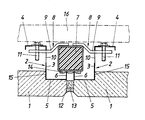
- These edge profiles 2 are essentially formed by a Z-profile, the edge-parallel web 3 of which protrudes on the inside of the plate and has an angled fastening flange 4 on the side facing away from the edge of the plate, which flange is at least approximately parallel to the plate.
- the leg 5 of the Z-profile protruding against the plate edge is provided with an angled edge web 6, which is flush with the vertical plate edge.
- clamping pieces 8 are provided, which are designed according to the exemplary embodiment as two-armed clamping levers 9 and pass through the web 3 of the edge profiles 2 in through openings 10 put. With the aid of clamping screws 11 supported on the mounting flange 4, which engage in a threaded bore of the clamping levers 9, these clamping levers 9 can be actuated, the clamping levers 9 engaging on the outer edge of the through openings 10 when the clamping screws 11 are tightened and pivoted about this edge .
- the upright 7 is clamped between the end faces of the angled edge webs 6 and the clamping lever 9 and the desired clamping connection between the upright 7 and the building boards 1 is established.
- the clamping forces are short-circuited via the edge profiles 2, so that the building boards 1 themselves remain stress-free.
- the remaining joints between the individual building boards 1 can be filled with a foam strip 12 and a kit layer 13, which results in a complete covering of the upright 7 without impairing the compensation of thermal expansion.
- thermal insulation 14 for example a plastic strip, can additionally be provided between the upright 7 on the one hand and the angled edge webs 6 or the clamping pieces 8 on the other hand, as is indicated in the exemplary embodiment between the edge webs 6 and the upright 7.
- the angled edge webs 6 of the Z-profile ensure a corresponding distance between the building boards 1 and the upright 7 in its area. So that due to this distance the entire building board does not have to be placed in front of the upright 7 by the height of the edge web 6, the building board forms a corresponding shoulder 15 against which the web 3 of the edge profile 2 bears.
- the fastening of the building boards 1 to uprights 7 with the aid of the clamping pieces 8 ensures that the building boards 1 are at a sufficient distance, for example from a possible inner cladding 16 for ventilation of the outer wall. It In such a case, however, it must be ensured that the horizontal legs of the profile frame of the building boards 1 enable a sufficient air throughput.
- the horizontal profile frame legs can be provided with corresponding air passage openings. In order to ensure a free flow path through these air passage openings, it is advantageous to set the shoulder 15 back relative to the projecting web of the horizontal edge profiles, so that a corresponding flow channel for the air passage remains free between the shoulder 15 and the web of the edge profiles. With such a design, the building boards 1 can be supported on the horizontal frame legs without affecting the rear ventilation of the outer wall.
- each of the building boards 1 is connected to the upright independently of the subsequent building boards. It is also possible for each building board to be detached from the uprights by loosening the associated clamping pieces 9.
- the edge profiles 2 are, as is customary, connected to the plate reinforcement, which is not shown for reasons of clarity.
Landscapes
- Engineering & Computer Science (AREA)
- Architecture (AREA)
- Civil Engineering (AREA)
- Structural Engineering (AREA)
- Physics & Mathematics (AREA)
- Electromagnetism (AREA)
- Building Environments (AREA)
Applications Claiming Priority (2)
| Application Number | Priority Date | Filing Date | Title |
|---|---|---|---|
| AT3026/85 | 1985-10-18 | ||
| AT302685A AT383172B (de) | 1985-10-18 | 1985-10-18 | Bauplatte fuer die aussenwand eines gebaeudes |
Publications (3)
| Publication Number | Publication Date |
|---|---|
| EP0220163A2 true EP0220163A2 (fr) | 1987-04-29 |
| EP0220163A3 EP0220163A3 (en) | 1988-08-17 |
| EP0220163B1 EP0220163B1 (fr) | 1990-08-29 |
Family
ID=3544149
Family Applications (1)
| Application Number | Title | Priority Date | Filing Date |
|---|---|---|---|
| EP19860890249 Expired - Lifetime EP0220163B1 (fr) | 1985-10-18 | 1986-09-08 | Panneau pour le mur extérieur d'un bâtiment |
Country Status (3)
| Country | Link |
|---|---|
| EP (1) | EP0220163B1 (fr) |
| AT (1) | AT383172B (fr) |
| DE (1) | DE3673748D1 (fr) |
Cited By (1)
| Publication number | Priority date | Publication date | Assignee | Title |
|---|---|---|---|---|
| CN111827528A (zh) * | 2020-06-29 | 2020-10-27 | 北新集团建材股份有限公司 | 一种减振龙骨、隔声墙体单元和隔声墙体 |
Family Cites Families (6)
| Publication number | Priority date | Publication date | Assignee | Title |
|---|---|---|---|---|
| FR778686A (fr) * | 1933-12-07 | 1935-03-22 | Nouveaux procédés pour la construction d'immeubles | |
| FR810491A (fr) * | 1936-09-07 | 1937-03-22 | Fibre Diamond | Procédé pour la fixation de plaques de revêtement obtenues par moulage de matières en feuilles |
| US2145469A (en) * | 1937-08-18 | 1939-01-31 | Merle C Scanland | Ornamental wall panel and means for securing the same |
| US2163381A (en) * | 1938-02-23 | 1939-06-20 | Marsan Edward Paul | Self-locking building block |
| US3065831A (en) * | 1959-04-24 | 1962-11-27 | Armco Steel Corp | Panel for curtain walls |
| FR1494247A (fr) * | 1966-07-26 | 1967-09-08 | Chantiers De Nantes Atel | Dispositif d'étanchétié pour panneau de façade |
-
1985
- 1985-10-18 AT AT302685A patent/AT383172B/de not_active IP Right Cessation
-
1986
- 1986-09-08 EP EP19860890249 patent/EP0220163B1/fr not_active Expired - Lifetime
- 1986-09-08 DE DE8686890249T patent/DE3673748D1/de not_active Expired - Fee Related
Cited By (1)
| Publication number | Priority date | Publication date | Assignee | Title |
|---|---|---|---|---|
| CN111827528A (zh) * | 2020-06-29 | 2020-10-27 | 北新集团建材股份有限公司 | 一种减振龙骨、隔声墙体单元和隔声墙体 |
Also Published As
| Publication number | Publication date |
|---|---|
| ATA302685A (de) | 1986-10-15 |
| DE3673748D1 (de) | 1990-10-04 |
| AT383172B (de) | 1987-05-25 |
| EP0220163B1 (fr) | 1990-08-29 |
| EP0220163A3 (en) | 1988-08-17 |
Similar Documents
| Publication | Publication Date | Title |
|---|---|---|
| DE4006605C1 (en) | Prefabricated sectional room - has floor with transverse support frame having composite sidewalls carrying appliances | |
| DD237529A5 (de) | Plattenfoermiges bauelement und baukonstruktion mit derartigen bauelementen | |
| EP0220163B1 (fr) | Panneau pour le mur extérieur d'un bâtiment | |
| DE202008009183U1 (de) | Fassadenelement | |
| DE2644559A1 (de) | Aus- und umbaubare trennwand | |
| DE69800671T2 (de) | Wandaufbau mit externer Isolierung und ein ein solchen Wandaufbau aufweisendes Bauwerk | |
| AT401788B (de) | Fassade | |
| DE7342923U (de) | Wärmedämmung für die Anordnung einer hinterlüfteten justierbaren Bauelementenverkleidung | |
| DE1459901C3 (de) | Gebäude, das eine Front mit Loggien aufweist | |
| DE1931427C3 (de) | Wandkonstruktion für Bauwerke | |
| DE3310284A1 (de) | Wohn-normcontainer | |
| DE29612763U1 (de) | Holzhaus und zu dessen Herstellung bestimmte Wandtafel | |
| DE2835054A1 (de) | Abdichtung fuer eine dehnungsfuge in einem fussboden | |
| DE19501088A1 (de) | Eckpfosten für eine Wandverkleidung aus mit einem Kunststoffrahmen versehenen Verkleidungselementen | |
| DE1805979C (de) | Verkleidungsplatte aus Asbestzement für Wände od. dgl | |
| DE69323890T2 (de) | Verbindungselement und dessen anwendung | |
| DE19828480A1 (de) | Bauplatte mit Halterung | |
| DE8800349U1 (de) | Installationsblock | |
| DE69410090T2 (de) | Vorgehängte Fassade in wabenförmiger Elementbauweise | |
| DE29825071U1 (de) | Bauplatte mit Halterung | |
| DE1929732U (de) | Fassadenverkleidungssatz. | |
| DE2225053C3 (de) | Verkleidung für Badewannen | |
| DE1509611A1 (de) | Vorrichtung zum Befestigen von Fassadenplatten od.dgl. auf einer Unterkonstruktion | |
| DE29711314U1 (de) | Wandverkleidung | |
| DE2203955A1 (de) | Deckenverkleidung |
Legal Events
| Date | Code | Title | Description |
|---|---|---|---|
| PUAI | Public reference made under article 153(3) epc to a published international application that has entered the european phase |
Free format text: ORIGINAL CODE: 0009012 |
|
| AK | Designated contracting states |
Kind code of ref document: A2 Designated state(s): BE CH DE FR GB IT LI NL SE |
|
| PUAL | Search report despatched |
Free format text: ORIGINAL CODE: 0009013 |
|
| AK | Designated contracting states |
Kind code of ref document: A3 Designated state(s): BE CH DE FR GB IT LI NL SE |
|
| 17P | Request for examination filed |
Effective date: 19880915 |
|
| 17Q | First examination report despatched |
Effective date: 19900207 |
|
| GRAA | (expected) grant |
Free format text: ORIGINAL CODE: 0009210 |
|
| AK | Designated contracting states |
Kind code of ref document: B1 Designated state(s): BE CH DE FR GB IT LI NL SE |
|
| PG25 | Lapsed in a contracting state [announced via postgrant information from national office to epo] |
Ref country code: IT Free format text: LAPSE BECAUSE OF FAILURE TO SUBMIT A TRANSLATION OF THE DESCRIPTION OR TO PAY THE FEE WITHIN THE PRE;WARNING: LAPSES OF ITALIAN PATENTS WITH EFFECTIVE DATE BEFORE 2007 MAY HAVE OCCURRED AT ANY TIME BEFORE 2007. THE CORRECT EFFECTIVE DATE MAY BE DIFFERENT FROM THE ONE RECORDED.SCRIBED TIME-LIMIT Effective date: 19900829 Ref country code: BE Effective date: 19900829 Ref country code: SE Free format text: THE PATENT HAS BEEN ANNULLED BY A DECISION OF A NATIONAL AUTHORITY Effective date: 19900829 Ref country code: NL Effective date: 19900829 Ref country code: FR Effective date: 19900829 Ref country code: GB Effective date: 19900829 |
|
| PG25 | Lapsed in a contracting state [announced via postgrant information from national office to epo] |
Ref country code: LI Effective date: 19900930 Ref country code: CH Effective date: 19900930 |
|
| REF | Corresponds to: |
Ref document number: 3673748 Country of ref document: DE Date of ref document: 19901004 |
|
| EN | Fr: translation not filed | ||
| NLV1 | Nl: lapsed or annulled due to failure to fulfill the requirements of art. 29p and 29m of the patents act | ||
| GBV | Gb: ep patent (uk) treated as always having been void in accordance with gb section 77(7)/1977 [no translation filed] | ||
| REG | Reference to a national code |
Ref country code: CH Ref legal event code: PL |
|
| PG25 | Lapsed in a contracting state [announced via postgrant information from national office to epo] |
Ref country code: DE Effective date: 19910601 |
|
| PLBE | No opposition filed within time limit |
Free format text: ORIGINAL CODE: 0009261 |
|
| STAA | Information on the status of an ep patent application or granted ep patent |
Free format text: STATUS: NO OPPOSITION FILED WITHIN TIME LIMIT |
|
| 26N | No opposition filed |