EP0220212B1 - Tragbares personalrechnersystem - Google Patents
Tragbares personalrechnersystem Download PDFInfo
- Publication number
- EP0220212B1 EP0220212B1 EP86902257A EP86902257A EP0220212B1 EP 0220212 B1 EP0220212 B1 EP 0220212B1 EP 86902257 A EP86902257 A EP 86902257A EP 86902257 A EP86902257 A EP 86902257A EP 0220212 B1 EP0220212 B1 EP 0220212B1
- Authority
- EP
- European Patent Office
- Prior art keywords
- container
- section
- computing system
- unit
- open position
- Prior art date
- Legal status (The legal status is an assumption and is not a legal conclusion. Google has not performed a legal analysis and makes no representation as to the accuracy of the status listed.)
- Expired - Lifetime
Links
Images


Classifications
-
- G—PHYSICS
- G06—COMPUTING OR CALCULATING; COUNTING
- G06F—ELECTRIC DIGITAL DATA PROCESSING
- G06F1/00—Details not covered by groups G06F3/00 - G06F13/00 and G06F21/00
- G06F1/16—Constructional details or arrangements
- G06F1/1613—Constructional details or arrangements for portable computers
- G06F1/1633—Constructional details or arrangements of portable computers not specific to the type of enclosures covered by groups G06F1/1615 - G06F1/1626
- G06F1/1662—Details related to the integrated keyboard
- G06F1/1667—Arrangements for adjusting the tilt angle of the integrated keyboard independently from the main body
-
- G—PHYSICS
- G06—COMPUTING OR CALCULATING; COUNTING
- G06F—ELECTRIC DIGITAL DATA PROCESSING
- G06F1/00—Details not covered by groups G06F3/00 - G06F13/00 and G06F21/00
- G06F1/16—Constructional details or arrangements
- G06F1/1613—Constructional details or arrangements for portable computers
- G06F1/1615—Constructional details or arrangements for portable computers with several enclosures having relative motions, each enclosure supporting at least one I/O or computing function
-
- G—PHYSICS
- G06—COMPUTING OR CALCULATING; COUNTING
- G06F—ELECTRIC DIGITAL DATA PROCESSING
- G06F1/00—Details not covered by groups G06F3/00 - G06F13/00 and G06F21/00
- G06F1/16—Constructional details or arrangements
- G06F1/1613—Constructional details or arrangements for portable computers
- G06F1/1633—Constructional details or arrangements of portable computers not specific to the type of enclosures covered by groups G06F1/1615 - G06F1/1626
- G06F1/1656—Details related to functional adaptations of the enclosure, e.g. to provide protection against EMI, shock, water, or to host detachable peripherals like a mouse or removable expansions units like PCMCIA cards, or to provide access to internal components for maintenance or to removable storage supports like CDs or DVDs, or to mechanically mount accessories
Definitions
- This invention relates to portable computing systems of the kind including: a container having first and second sections; attaching means mounted on said first and second sections and enabling said first and second sections tc be moved between a closed position for transporting said computing system and an open position for operating said computing system; computing means mounted in said container; and a keyboard unit,a display unit and a read/write unit mounted in said container and adapted to be presented in operative positions when said first and second sections are moved from said closed to said open position, wherein said keyboard unit is mounted in said first section which serves as a base for said system, the arrangement being such that, when said first and second sections are moved from said closed to said open position, said attaching means is adapted to hold said second section relative to said first section such that said container is maintained in said open position.
- a portable computing system is known from U.S. Patent No. 4 294 496.
- first and second enclosures are hinged together and can be closed together to form a suitcase - type cabinet.
- the first enclosure includes a main frame having a display at its closable end, openings being provided for the reception of disc drives through a covering over the display.
- extensions of the top and side panels of the first enclosure extend beyond the display to form a hood.
- the second enclosure has a keyboard at its closable end, a front panel backing the keyboard and a carrying handle extending from the front panel.
- the first enclosure In the open position, the first enclosure is placed on a support surface, the second enclosure being supported by foot pads which contact the support surface at a location remote from the hinge. This has the disadvantage that a large amount of support surface area is required to support the computing system in its operating position.
- a portable computing system of the kind specified is known from EP-A-0 126 542.
- the known system includes a cover hinged to a base.
- the base holds a keyboard and is adapted to receive a plurality of selectively pluggable and removable cartridges Including semiconductor memories which serve to replace floppy or hard disks normally used with personal computers.
- a liquid crystal display unit is mounted on the interior surface of the cover. The angle of the lid may be adjusted to the user's convenience.
- a portable keyboard/display terminal Including a base portion and a cover, wherein a display screen is recessed into the interior of the cover, which is hinged to the base portion.
- a handle provided on the base portion enables the terminal to be readily carried.
- a portable computer contained in an outer metal case having a base, a top cover, a display housing and a rear cover.
- the display housing is pivotally connected to the base by two hinge assemblies, for swinging movement between a closed and latched position on the base and an upward and rearwardly inclined angle for viewing by an operator.
- a keyboard is located in the base.
- a portable computing system of the kind specified characterized in that said attaching means includes first and second link members mounted on said first and second section respectively, said first and second link members being pivotally linked together by fastener means, said second link member being provided with a projection adapted to cooperate with a notch in said first link member to maintain said container in said open position, in that said display unit is mounted on said second link member, such that said display unit is moved from a first position in which said display unit is substantially parallel to said first section when said container is in said closed position to a second position in which said display unit is positioned at a viewing angle relative to an operator using said keyboard unit when said container is in said open position, and in that said read/write unit is mounted in support means mounted for pivotal movement on said second section, such that when said container is in said open position said support means is moved by gravity to an operative position.
- An advantage of a portable computing system according to the invention is that it is simple and inexpensive to implement.
- a further advantage is that the keyboard unit, display unit and read/write unit are presented in an operative position when the container is opened to the operating position.
- the container for the computer system is implemented in the form of an attache case, thereby minimizing the risk of theft of the computing system.
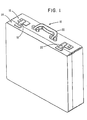
- Fig. 1 is a general, perspective view of a container 10 which houses a known computing system 12, shown schematically in Fig. 3.
- the container 10 is an attache case.
- the container 10 is comprised of first and second sections 14 and 16, respectively, which are shown in the closed position in Fig. 1 for transporting it.
- Conventional locks 18 and 20 are used to lock the two sections 14 and 16 together, and a handle 22 is used for carrying the container 10.
- the first section 14 of the container 10 is placed on a table 24, for example, the locks 18 and 20 are opened, and the second section 16 is raised to the open or operating position shown in Fig. 2.
- the second section 16 forms an angle of less than 90 degrees with the first section 14 when the container 10 is in the operating position, and it is held in this position by a hinge 25 (Fig. 5) and by support members 26 and 28 which will be described further hereinafter.
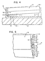
- the means for mounting the keyboard unit 32 within the container 10 is shown in Fig. 4, and this means includes a hinge 40 and a stop 42.
- One leaf 40 - 1 of the hinge 40 is secured to the first section 14, and the remaining leaf 40 - 2 is secured to the keyboard unit 32 to enable the unit 32 to pivot slightly about the hinge pin 40 - 3.
- the stop 42 is conventional and adjustable and is used to enable the end 32 - 1 of the keyboard unit 32 to be supported in a raised position when the keyboard unit 32 is pivoted slightly about the hinge pin 40 - 3 (counterclockwise as viewed in Fig. 4) to change the angle of the keyboard unit 32 relative to the table 24 to suit operator preferences.
- the hinge 40 may also be a conventional separable hinge which permits the keyboard unit to be removed from the container 10 to accommodate operator preference. Prior to closing the container 10, the stop 42 is returned to its lower position to provide for compactness within the container 10.
- the means for mounting the display unit 34 within the container 10 includes the support members 26 and 28 (Fig. 2) alluded to earlier, herein. Because the support members 26 and 28 are identical, except for being mirror images of each other, a discussion of only support member 26 will follow.
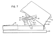
- the support member 26 is comprised of two links 26 - and 26 - 2 as shown in Figs 5, 6, and 7.
- Link 26 - 1 has one end pivotally joined to a sidewall 14 - 1 of the first section 14 by a washer 44 and a fastener 46 as shown best in Fig. 6.
- the remaining end of link 26 - 1 Is pivotally joined to link 26 - 2 (between Its ends) by a fastener 48.
- One end of link 26 - 2 is pivotally joined to the sidewall 16 - 1 of the second section 16 by a washer 50 and a fastener 52 as shown best in Fig. 6, and the remaining end of link 26 - 2 has an offset portion or tang 54 thereon.
- the tang 54 fits into a notch 56 (Fig.
- the support members 26 and 28 also perform the function of moving the display unit 34 from a first position in which the display unit 34 is substantially parallel to the first section 14 when the container 10 is closed and for moving the display unit 34 to a second position, shown in Fig. 5, where the display unit 34 is positioned at a proper viewing angle for a user of the system 10 who is operating the keyboard unit 32.
- a spacer block 62 (Figs. 5, 6, and 7) positioned between the display unit 34 and the link 26 - 2, and the fastener 48, which couples the links 26 -1 and 26 - 2 together, is also used to secure one end of the spacer block 62 to the link 26 - 2.
- the remaining end of the spacer block 62 is secured to the link 26 - 2 by a fastener 64.
- the spacer block 62 is secured to the display unit 34 by a suitable adhesive.
- the means for mounting disc drive units- 36 and 38 Is shown In Figs. 2 and 5, and it includes the supporting member or chamber 66 shown in Fig. 5.
- the supporting chamber 66 is essentially a narrow but wide container which has its lower end pivotally joined to a cross member 68 by a hinge 70.
- the cross member 68 is supported within the second section 16.
- the movement of the supporting chamber 66 out of the second section 16 is limited by a flexible tension member 72 as shown in Fig. 5.
- the first section 14 and the second section 16 are held apart at an included angle of less than 90 degrees causing the center of gravity of the chamber 66 to produce a turning moment which pivots the chamber 66 about the hinge 70 to the operating position shown.
- the supporting chamber 66 is divided into three compartments, as shown in Fig. 2, for the preferred embodiment being described.
- Disc drive unit 36 is placed in one compartment
- disc drive unit 38 is placed in the second compartment
- the third compartment 74 may be used for the storage of floppy discs associated with the disc drive units 36 and 38.
- a floppy disc 76 (only a portion shown in Fig. 5) is aligned with the receiving slot 78 for insertion into the disc drive unit 38 shown only in dashed outline in Fig. 5.
- the supporting chamber 66 has attractive padding material 80 (Fig. 5) located at least on the side which faces the keyboard unit 32 so that these two units are insulated from shock or damage when the second section 16 is moved towards the first section 14 for closing.
- the tension member 72 (Fig. 5) also keeps the supporting member 66 from crashing against the keyboard unit 14 as the container 10 is closed.
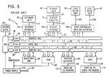
- the computing system 12 which is housed in the container 10 is shown In Fig. 3. Because the computing system 12 is conventional, it will be described only briefly herein.
- the system 12 includes a central processing unit (CPU) 82 and system clock 84 along with buffers 86, 88, and 90 which are used to couple the address bus 92, data bus 94, and control bus 96, respectively, to the CPU 82.
- CPU central processing unit
- the system 12 also Includes a bootstrap ROM 98, a RAM 100, a keyboard interface 102, a display interface 104, a disc controller chip and interface 106, a printer interface 108, and a communication interface such as the universal asynchronous receiver transmitter (UART) 110, with each of the component elements mentioned in this sentence being coupled to the address bus 92, the data bus 94, and the control bus 96 as shown by lines A, D, and C, respectively, which are shown only for the display interface 104 to simplify the drawing.
- the system 12 also includes a power supply 112 which converts 110 VAC to the necessary voltage levels for the various components shown in Fig. 3. While the system 12 is shown as being operated from 110 VAC, the power supply 112 could also represent a battery- operated system where appropriate.
- the keyboard unit 32 is connected to the keyboard Interface 102 by conductors shown as 114.
- the display unit 34 is coupled to display circuits 116 by conductors 118 which are routed under fabric 120 (partially broken away in Fig. 2) to protect the conductors and to present a neat appearance for the interior of the container 10.
- the display unit 34 is of the liquid crystal variety to provide compactness.
- the data to be displayed appears within the rectangle 122, although other designs or layouts may be used.
- the display circuits 116 associated with the particular display unit 34 used are coupled to the display interface 104 by conductors 124.
- the disc drive unit 36 and the disc drive unit 38 are coupled to the disc controller chip and interface 106 by conductors 126 and 128, respectively, which also are located under the fabric 120 (Fig. 2) to present a neat appearance to the interior of the container 10.
- a coupling 130 and associated conductor 132 are used to couple the printer interface 108 (Fig. 3) to a printer (not shown).
- a coupling 134 and associated conductor 136 are used to couple these ports and modems to the UART 110 shown in Fig. 3.
- the couplings 130 and 134 are shown only schematically in Fig. 3. In certain situations, the modems may be included on a printed circuit card which is part of the system 12.
- the elements of the computing system 12 such as the CPU 82, RAM 100 and various interfaces like 102 and 106, for example, are located in a compartment 138 (Fig. 4) which is located in the keyboard unit 32.
- the size of the container 10 may be to accommodate the particular computing adjusted to accommodate the particular computing system 12 employed.
- the computing system 12 may be conventionally operated by entering data and instructions on the keys 32 - 2, 32 - 3, for example, of the keyboard unit 32, by using the disc drive units 36 and 38 and the display unit 34, and by outputting data to peripheral devices like a printer via the coupling 130.
Landscapes
- Engineering & Computer Science (AREA)
- Computer Hardware Design (AREA)
- Theoretical Computer Science (AREA)
- Physics & Mathematics (AREA)
- General Engineering & Computer Science (AREA)
- Human Computer Interaction (AREA)
- General Physics & Mathematics (AREA)
- Mathematical Physics (AREA)
- Purses, Travelling Bags, Baskets, Or Suitcases (AREA)
- Casings For Electric Apparatus (AREA)
- Packaging For Recording Disks (AREA)
Claims (6)
Applications Claiming Priority (2)
| Application Number | Priority Date | Filing Date | Title |
|---|---|---|---|
| US727944 | 1985-04-26 | ||
| US06/727,944 US4736332A (en) | 1985-04-26 | 1985-04-26 | Portable personal computing system |
Publications (2)
| Publication Number | Publication Date |
|---|---|
| EP0220212A1 EP0220212A1 (de) | 1987-05-06 |
| EP0220212B1 true EP0220212B1 (de) | 1990-03-21 |
Family
ID=24924750
Family Applications (1)
| Application Number | Title | Priority Date | Filing Date |
|---|---|---|---|
| EP86902257A Expired - Lifetime EP0220212B1 (de) | 1985-04-26 | 1986-04-07 | Tragbares personalrechnersystem |
Country Status (6)
| Country | Link |
|---|---|
| US (1) | US4736332A (de) |
| EP (1) | EP0220212B1 (de) |
| JP (1) | JPS62502639A (de) |
| CA (1) | CA1247221A (de) |
| DE (1) | DE3669795D1 (de) |
| WO (1) | WO1986006516A1 (de) |
Families Citing this family (48)
| Publication number | Priority date | Publication date | Assignee | Title |
|---|---|---|---|---|
| USD301471S (en) | 1986-03-13 | 1989-06-06 | Kabushiki Kaisha Toshiba | Combined copying machine and electronic computer |
| JPH0512062Y2 (de) * | 1986-11-18 | 1993-03-26 | ||
| JPS63103123U (de) * | 1986-12-25 | 1988-07-04 | ||
| DE8708904U1 (de) * | 1987-06-25 | 1988-04-28 | Systec Gesellschaft für Digital-Analog-Technik mbH, 1000 Berlin | Informations- und Kommunikationsgerät |
| GB8728644D0 (en) * | 1987-12-08 | 1988-01-13 | Ifejika V A | Portable information processing apparatus |
| US4903221A (en) * | 1988-10-31 | 1990-02-20 | Zenith Electronics Corporation | Keyboard latching arrangement for portable computers |
| JPH02148114A (ja) * | 1988-11-30 | 1990-06-07 | Nippon I B M Kk | パーソナル・コンピュータ |
| US4861970A (en) * | 1989-01-17 | 1989-08-29 | Hwang Kuo H | Multipurpose calculator |
| JPH0733264Y2 (ja) * | 1989-02-07 | 1995-07-31 | アルプス電気株式会社 | フラットディスプレイ支持機構 |
| USRE36654E (en) * | 1989-03-28 | 2000-04-11 | In Focus Systems, Inc. | Stacked LCD color display |
| CA1323922C (en) * | 1989-09-26 | 1993-11-02 | William Fang | Personal health monitor enclosure |
| US5239444A (en) * | 1989-10-20 | 1993-08-24 | Kabushiki Kaisha Toshiba | Tiltable portable electronic apparatus with sliding tilt leg |
| DE3935042C1 (en) * | 1989-10-20 | 1991-03-07 | Nixdorf Computer Ag, 4790 Paderborn, De | Flat screen VDU for data processor - has support consisting of stand and linkage for pivotable retention |
| JP2766347B2 (ja) * | 1989-10-31 | 1998-06-18 | 株式会社東芝 | 小型電子機器 |
| US5080452A (en) * | 1990-03-01 | 1992-01-14 | Tuckman Tab R | Integral storage receptacle for personal computer |
| US5051868A (en) * | 1990-07-25 | 1991-09-24 | Sun Microsystems, Inc. | Computer construction |
| DE4032959A1 (de) * | 1990-10-17 | 1992-04-23 | Josef Schreiner | Portabler computer |
| USD344074S (en) | 1991-01-04 | 1994-02-08 | Collins Steven M | Combined laptop computer with cellular telephone and carrying case therefor |
| US5305183A (en) * | 1991-07-09 | 1994-04-19 | Edison Welding Institute | Portable personal computer with passive backplane having a doublesided staggered connector array |
| US5260884A (en) * | 1991-07-17 | 1993-11-09 | Jonathan Stern | Brief case having integral computer |
| US5227953A (en) * | 1991-10-18 | 1993-07-13 | Hewlett-Packard Company | Apparatus for retaining and electrically interconnecting multiple devices |
| JPH05189084A (ja) * | 1992-01-10 | 1993-07-30 | Toshiba Corp | 小形電子機器 |
| US5212628A (en) * | 1992-01-17 | 1993-05-18 | The I.D.E.A. Corporation | Modular portable work station having a movable support tray |
| US5214574A (en) * | 1992-04-16 | 1993-05-25 | Chang Bo E | Portable computer housing in combination with a portable computer |
| WO1994000037A1 (en) * | 1992-06-24 | 1994-01-06 | Cad Forms Technology Inc. | A pen based computer protective case |
| US5668570A (en) * | 1993-06-29 | 1997-09-16 | Ditzik; Richard J. | Desktop computer with adjustable flat panel screen |
| US5495389A (en) * | 1993-10-08 | 1996-02-27 | International Business Machines Corporation | Personal computer with configurational flexibility and service features |
| JPH07210271A (ja) * | 1994-01-13 | 1995-08-11 | Citizen Watch Co Ltd | 携帯型コンピュータ |
| USD378676S (en) * | 1994-09-09 | 1997-04-01 | International Business Machines Corporation | Holder for portable computing device |
| US5552957A (en) * | 1994-09-09 | 1996-09-03 | International Business Machines Corporation | Portable computer field kit |
| US6037548A (en) * | 1996-02-22 | 2000-03-14 | Siemens Nixdorf Informationssysteme Ag | Scales for retail outlets |
| US5761034A (en) * | 1997-01-06 | 1998-06-02 | Chu; Shi | Portable main frame for a computer having upper and lower covers provided with computer components and pivotally connected together |
| JPH10262719A (ja) * | 1997-03-27 | 1998-10-06 | Mitsubishi Electric Corp | ノートパソコン収納ケース |
| US6654235B2 (en) * | 2000-01-25 | 2003-11-25 | Bruce Imsand | Portable workstation computer |
| DE20119393U1 (de) * | 2001-11-28 | 2003-04-10 | Bormann EDV + Zubehör GmbH, 86356 Neusäß | Computerkoffer |
| KR100456582B1 (ko) * | 2001-12-06 | 2004-11-10 | 삼성전자주식회사 | 컴퓨터 |
| TW539147U (en) * | 2002-02-06 | 2003-06-21 | Hon Hai Prec Ind Co Ltd | Computer case |
| US20050190542A1 (en) * | 2004-03-01 | 2005-09-01 | Chee Bill T.C. | Case for handheld device |
| CN2750629Y (zh) * | 2004-11-26 | 2006-01-04 | 鸿富锦精密工业(深圳)有限公司 | 电子装置壳体 |
| US20060133052A1 (en) * | 2004-12-17 | 2006-06-22 | Harmon Roger W | Foldable electronic device having a flexible hinge mechanism |
| US20070177343A1 (en) * | 2006-02-02 | 2007-08-02 | Ben Ming Hsia | Portable personal computer |
| US20070177344A1 (en) * | 2006-02-02 | 2007-08-02 | Ben Ming Hsia | Portable personal computer |
| US8240359B2 (en) * | 2006-04-17 | 2012-08-14 | Gerald Garrett | Liquid storage and cooling computer case |
| CN102917563B (zh) * | 2011-08-04 | 2016-10-12 | 中海沥青(泰州)有限责任公司 | 连动装置 |
| US9092200B2 (en) * | 2012-01-10 | 2015-07-28 | Hewlett-Packard Development Company, L.P. | Display device |
| CN108958382A (zh) * | 2018-08-03 | 2018-12-07 | 英业达科技有限公司 | 笔记本电脑 |
| TWI791377B (zh) * | 2021-03-15 | 2023-02-01 | 仁寶電腦工業股份有限公司 | 電子裝置 |
| KR102736199B1 (ko) * | 2023-03-08 | 2024-11-28 | 엘지전자 주식회사 | 디스플레이 디바이스 |
Citations (1)
| Publication number | Priority date | Publication date | Assignee | Title |
|---|---|---|---|---|
| EP0126542A2 (de) * | 1983-04-12 | 1984-11-28 | MicroOffice Systems, Technology, Inc. | Tragbarer Rechner |
Family Cites Families (20)
| Publication number | Priority date | Publication date | Assignee | Title |
|---|---|---|---|---|
| US3920979A (en) * | 1973-10-19 | 1975-11-18 | Jack S Kilby | Electronic check writer |
| US4084213A (en) * | 1977-02-22 | 1978-04-11 | Modern Controls, Inc. | Portable keyboard/display terminal |
| USD253438S (en) | 1977-09-06 | 1979-11-20 | Markley Harold T | Combined work case, pad holder and calculator |
| US4222109A (en) * | 1978-06-05 | 1980-09-09 | Siwula John T | Electronic checkbook |
| US4308588A (en) * | 1978-06-05 | 1981-12-29 | Siwula John T | Electronic checkbook |
| USD256189S (en) | 1978-06-20 | 1980-08-05 | George Rapoport | Combined attache case and detachable file folder |
| US4224675A (en) * | 1978-12-11 | 1980-09-23 | Pinkerman John P | Portable checkbook-balance calculating device |
| ATE5105T1 (de) * | 1979-06-07 | 1983-11-15 | Bioself International Inc. | Taschenrechner fuer familienplanung. |
| USD260202S (en) | 1979-06-15 | 1981-08-18 | Computer Transceiver Systems, Inc. | Computer terminal case |
| USD266208S (en) | 1979-06-25 | 1982-09-21 | Cannon Gary L | Video game tote case |
| US4294496A (en) * | 1979-08-03 | 1981-10-13 | Gm Research | Portable computer enclosure |
| USD267834S (en) | 1980-03-20 | 1983-02-08 | Yew Tow S | Doctor's attache case |
| GB2100065A (en) * | 1981-03-18 | 1982-12-15 | Adams David John | Portable electronic equipment |
| DE3119209A1 (de) * | 1981-05-14 | 1982-12-09 | Robert Bosch Gmbh, 7000 Stuttgart | "tragbares mobiles datenterminal" |
| JPS58163007A (ja) * | 1982-03-24 | 1983-09-27 | Fanuc Ltd | 携帯型nc自動プログラミング装置 |
| USD277284S (en) | 1982-10-01 | 1985-01-22 | High Technology Solutions, Inc. | Keyboard |
| US4571456B1 (en) * | 1982-10-18 | 1995-08-15 | Grid Systems Corp | Portable computer |
| US4496943A (en) * | 1982-11-18 | 1985-01-29 | Portable Terminal Corp. | Portable information display |
| GB2143117A (en) * | 1983-07-15 | 1985-02-06 | Richard Douglas Mountford | Case for accommodating a micro computer |
| US4669053A (en) * | 1984-05-31 | 1987-05-26 | Zenith Electronics Corporation | Portable personal computer |
-
1985
- 1985-04-26 US US06/727,944 patent/US4736332A/en not_active Expired - Fee Related
-
1986
- 1986-02-20 CA CA000502340A patent/CA1247221A/en not_active Expired
- 1986-04-07 EP EP86902257A patent/EP0220212B1/de not_active Expired - Lifetime
- 1986-04-07 JP JP61501974A patent/JPS62502639A/ja active Pending
- 1986-04-07 WO PCT/US1986/000683 patent/WO1986006516A1/en not_active Ceased
- 1986-04-07 DE DE8686902257T patent/DE3669795D1/de not_active Expired - Lifetime
Patent Citations (1)
| Publication number | Priority date | Publication date | Assignee | Title |
|---|---|---|---|---|
| EP0126542A2 (de) * | 1983-04-12 | 1984-11-28 | MicroOffice Systems, Technology, Inc. | Tragbarer Rechner |
Also Published As
| Publication number | Publication date |
|---|---|
| CA1247221A (en) | 1988-12-20 |
| WO1986006516A1 (en) | 1986-11-06 |
| DE3669795D1 (de) | 1990-04-26 |
| JPS62502639A (ja) | 1987-10-08 |
| US4736332A (en) | 1988-04-05 |
| EP0220212A1 (de) | 1987-05-06 |
Similar Documents
| Publication | Publication Date | Title |
|---|---|---|
| EP0220212B1 (de) | Tragbares personalrechnersystem | |
| US5107402A (en) | Portable computer provided with a tilting screen articulated thereon by tilting linkage with a bent shape | |
| US6016248A (en) | Hand held tablet computer having external mechanisms for facilitating positioning and operation | |
| JP3073121B2 (ja) | 表示機器の外装構造 | |
| US6304431B1 (en) | Portable computer system having ergonomic keyboard and detachable display unit | |
| US5200913A (en) | Combination laptop and pad computer | |
| US4742478A (en) | Housing for a portable computer | |
| US6118653A (en) | Camera mounting mechanism for supporting an electronic camera on a portable computer | |
| JP3627156B2 (ja) | ポータブル・コンピューティング・システムのパッケージング構造 | |
| US6867961B2 (en) | Portable computer | |
| US4839837A (en) | Three layered laptop computer | |
| KR100284300B1 (ko) | 휴대형 컴퓨터 | |
| US5847924A (en) | Notebook computer assembly having an attachable compact extension module for connecting peripheral equipment to a notebook computer | |
| US20050083644A1 (en) | Portable computer | |
| US20030142472A1 (en) | Portable computer having a latch apparatus | |
| US5805125A (en) | Portable information processing apparatus and liquid crystal display device | |
| EP0730216A1 (de) | Tragbares Informationsverarbeitungsgerät | |
| JPH10124186A (ja) | ポータブルコンピュータ | |
| JPH08314569A (ja) | 可搬型情報処理装置 | |
| US6629636B1 (en) | Sales transaction terminal device | |
| EP0793163A2 (de) | Tragbarer Rechner | |
| EP0730215A1 (de) | Tragbares Informationsverabeitungsgerät und Tragevorrichtung für ein tragbares Informationsverarbeitungsgerät | |
| JP2500278B2 (ja) | 電子機器 | |
| USRE39429E1 (en) | Combination laptop and pad computer | |
| US5272598A (en) | Portable electronic apparatus having an interchangeable detachable battery and optional component for expanding a function |
Legal Events
| Date | Code | Title | Description |
|---|---|---|---|
| PUAI | Public reference made under article 153(3) epc to a published international application that has entered the european phase |
Free format text: ORIGINAL CODE: 0009012 |
|
| AK | Designated contracting states |
Kind code of ref document: A1 Designated state(s): DE FR GB |
|
| 17P | Request for examination filed |
Effective date: 19870415 |
|
| DET | De: translation of patent claims | ||
| 17Q | First examination report despatched |
Effective date: 19890223 |
|
| GRAA | (expected) grant |
Free format text: ORIGINAL CODE: 0009210 |
|
| AK | Designated contracting states |
Kind code of ref document: B1 Designated state(s): DE FR GB |
|
| REF | Corresponds to: |
Ref document number: 3669795 Country of ref document: DE Date of ref document: 19900426 |
|
| ET | Fr: translation filed | ||
| PLBE | No opposition filed within time limit |
Free format text: ORIGINAL CODE: 0009261 |
|
| STAA | Information on the status of an ep patent application or granted ep patent |
Free format text: STATUS: NO OPPOSITION FILED WITHIN TIME LIMIT |
|
| 26N | No opposition filed | ||
| PGFP | Annual fee paid to national office [announced via postgrant information from national office to epo] |
Ref country code: FR Payment date: 19920327 Year of fee payment: 7 |
|
| PGFP | Annual fee paid to national office [announced via postgrant information from national office to epo] |
Ref country code: GB Payment date: 19920401 Year of fee payment: 7 |
|
| PGFP | Annual fee paid to national office [announced via postgrant information from national office to epo] |
Ref country code: DE Payment date: 19920428 Year of fee payment: 7 |
|
| REG | Reference to a national code |
Ref country code: GB Ref legal event code: 732E |
|
| REG | Reference to a national code |
Ref country code: FR Ref legal event code: TP |
|
| PG25 | Lapsed in a contracting state [announced via postgrant information from national office to epo] |
Ref country code: GB Effective date: 19930407 |
|
| GBPC | Gb: european patent ceased through non-payment of renewal fee |
Effective date: 19930407 |
|
| PG25 | Lapsed in a contracting state [announced via postgrant information from national office to epo] |
Ref country code: FR Effective date: 19931229 |
|
| PG25 | Lapsed in a contracting state [announced via postgrant information from national office to epo] |
Ref country code: DE Effective date: 19940101 |
|
| REG | Reference to a national code |
Ref country code: FR Ref legal event code: ST |