EP0220242B1 - Chevalet pour sechage de vetements et son receptacle - Google Patents
Chevalet pour sechage de vetements et son receptacle Download PDFInfo
- Publication number
- EP0220242B1 EP0220242B1 EP86902742A EP86902742A EP0220242B1 EP 0220242 B1 EP0220242 B1 EP 0220242B1 EP 86902742 A EP86902742 A EP 86902742A EP 86902742 A EP86902742 A EP 86902742A EP 0220242 B1 EP0220242 B1 EP 0220242B1
- Authority
- EP
- European Patent Office
- Prior art keywords
- stanchion
- receptacle
- assembly
- relation
- interior
- Prior art date
- Legal status (The legal status is an assumption and is not a legal conclusion. Google has not performed a legal analysis and makes no representation as to the accuracy of the status listed.)
- Expired
Links
- 238000001035 drying Methods 0.000 title claims abstract description 19
- XLYOFNOQVPJJNP-UHFFFAOYSA-N water Substances O XLYOFNOQVPJJNP-UHFFFAOYSA-N 0.000 claims abstract description 12
- 230000000717 retained effect Effects 0.000 claims abstract description 8
- 238000010276 construction Methods 0.000 claims description 3
- 230000014759 maintenance of location Effects 0.000 claims 1
- 230000001419 dependent effect Effects 0.000 description 2
- 235000019687 Lamb Nutrition 0.000 description 1
- 241000618809 Vitales Species 0.000 description 1
- 230000000712 assembly Effects 0.000 description 1
- 238000000429 assembly Methods 0.000 description 1
- 230000015556 catabolic process Effects 0.000 description 1
- 238000003780 insertion Methods 0.000 description 1
- 230000037431 insertion Effects 0.000 description 1
- 230000002093 peripheral effect Effects 0.000 description 1
Images

Classifications
-
- D—TEXTILES; PAPER
- D06—TREATMENT OF TEXTILES OR THE LIKE; LAUNDERING; FLEXIBLE MATERIALS NOT OTHERWISE PROVIDED FOR
- D06F—LAUNDERING, DRYING, IRONING, PRESSING OR FOLDING TEXTILE ARTICLES
- D06F57/00—Supporting means, other than simple clothes-lines, for linen or garments to be dried or aired
Definitions
- the present invention relates to a drying rack for clothes or like articles including an upstanding stanchion removably secured to an underlying receptacle positioned for collection of water dripping from suspended wet clothes or articles supported on arms connected to the stanchion.
- Drying structures including drying racks which are structured to support garments, clothes or like articles thereon have been known and in use for many years.
- the structure of such prior art devices includes an upstanding rack having a plurality of arms extending outwardly from an upper end thereof wherein the arms are spaced apart from one another and structured to have clothes, garments or the like suspended therefrom.
- Such an assembly should therefore include some type of cooperatively positioned receptacle and further the entire assembly preferably should be collapsible so as to allow storage in small areas.
- US-A-3023912 discloses a clothing drying assembly of the type primarily designed to support clothes and like articles for drying, said assembly comprising:
- clothes may be supported on any of the outwardly extending arms and thereby exposed to the air so as to facilitate drying. Water dripping from the drying garments is collected in the underlying receptacle means for later disposal.
- said support means includes at least one but preferably a plurality of arms radially extending outwardly from a centrally disposed hub portion wherein the plurality of arms and hub portion are of an integral, one-piece construction.
- the arms and the hub portion have a substantially hollow interior which is accessible from an under portion of the mounting means.
- the mounting means When in an operative position the mounting means is removably secured to a top free end of the stanchion through insertion of the extremity thereof into the hollow interior of the hub portion.
- the mounting means is removably attached in overlying and retained engagement with the connecting means.
- the connecting means in this embodiment, comprises a plurality of connecting arms extending radially outward from a central socket wherein the connecting arms are collectively dimensioned and configured to correspond to the plurality of arms of the mounting means. Accordingly, the hollow- ness of the mounting means allows its positioning in a nested fashion overlying the plurality of connecting arms such that the hub portion covers the centrally located socket of the connecting means.
- Further retaining means include at least a first and second retaining portion secured to an inner surface of the receptacle means and being dimensioned and structured to removably engage and retain stanchion portions. Accordingly, the stanchion and the mounting means are both retained in at least partially surrounding and enclosed relation on the interior of the receptacle means for storage of the entire assembly in a minimal space. Further embodiments of the invention are described in the dependent claims 2-12.
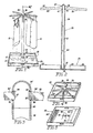
- the drying assembly of the present invention comprises a receptacle means generally indicated as 20 which includes peripheral walls 22 integrally connected to and extending upwardly from a floor 24 of the receptacle. These elements define the receptacle interior which has an overall dimension both longitudinal and transverse of predetermined length so as to catch water dripping from articles 10 such as clothes or the like being dried.
- the assembly further comprises a stanchion 30 which, in the preferred embodiment, includes two stanchion portions 34 and 36 having their correspondingly positioned ends interconnected to one another as at 42. Further, the stanchion portions are interconnected so as to be aligned in substantially coaxial relation to one another thereby defining the entire stanchion 30 extending upwardly from the floor 24 and the interior of the receptacle means 20.
- a connecting means includes a connecting socket 32 integrally formed on the interior of the receptacle means 20 and being structured to be substantially hollow so as to surround, and thereby support the lower or free end 35 of stanchion portion 34. It should be further noted that the location of socket 32 is dependent upon the overall configuration and disposition of a plurality of arms 50 comprising an arm means which will be described in greater detail hereinafter.
- An important feature of the present invention is the disposition of the interior of the receptacle means 20 in underlying relation to the plurality of arms 50 such that water dripping from garments 10 will fall into and be collected as at 12 into the interior of the receptacle means 20.
- the stanchion 30 serves as a support means in that mounting means generally indicated as 37 is movably attached as at 40 to the upper or free end 41 of stanchion portion 36.
- the mounting means includes a central hub portion 38 interconnected to end 41 in telescoping relation as at connection 40.
- Arm means is connected to the hub portion 38 and comprises a plurality of arms 50 extending radially outward from hub portion 38 in substantially equally spaced relation to one another.
- the plurality of arms 50 and the interior of the receptacle means 22 are relatively disposed such that any garments or clothes 10 beings suspended from the various arms must be posi.. tioned in overlying relation to the interior of the: receptacle means 20.
- a collection of water 12 wil I thereby be maintained within receptacle mean:. 20.
- each of the arms 50 are integrally attached to the hub portion 38 and when the mounting means 37 is removed from the stanchion portion 36 it may be stored as a single piece (Fig. 4) in the interior of the receptacle, means 20. More specifically, in this embodiment the hub portion may be connected to or telescopically fitted within the connecting socket 32 as also shown in Figure 4.
- the hub, portion 38 comprises a plurality of apertures 36 spaced about the outer periphery from one another. These apertures are structured and disposed to allow connection of the individual arms 50' wherein upstanding finger 54 serves to secure the corresponding end 57 of each of the arms 50' on the interior of the hub portion 38'. Breakdown or collapse of this embodiment occurs by removing each of the individual arms 50' and storing such arms individually on the interior of the receptacle means 20.
- the stanchion portions 34 and 36 are separable from one another and are also separable from the receptacle means 20 and the mounting means 37 respectively. Therefore, each of the stanchion portions 34 and 36 are mounted on the interior of the receptacle means as are the remainder of the components of the assembly.
- each of the arms 50 and/or 50' include a plurality of notches 52 on the upper longitudinal edge thereof. These notches are to secure the individual garments or clothing 10 on the arms and prevent inadvertent removal therefrom. While the embodiment of Figure 1 shows the garments individually attached to the arms without the aid of conventional clothes hangers, such notches 52 are structured to supportingly engage such conventional clothes hangers and the garments or clothes may be supported thereon and in turn supported from the individual arms 50 or 50' by conventinal clothes hangers.
- the receptacle means 20 includes upstanding stanchion 30 including stanchion portions 34 and 36 serving to support at an upper free end as at 40, mounting means 60.
- the mounting means in this embodiment includes a hub portion 62 and arm means comprising at least one and preferably a plurality of radially extending arms 64 directed outwardly from hub 62.
- the hub portion 62 and the plurality of arms 64 comprising the arm means is formed into an integral, one-piece construction wherein each of the arms 64 includes notches 52' formed along an upper edge thereof. Each of these notches is dimensioned and configured to receive a conventional clothes hanger 53 or the like for supporting the articles of clothing 10 on the individual arm 64.
- each of the stanchion portions 34 and 36 include an end portion 41' and 41 respectively which is dimensioned and configured to fit within either the opposite end 35', 35 of the other stanchion portion or within the interior of the hub portion 62.
- the mounting means 60 including the plurality of arms 64 and the hub portion 62 have a hollow interior portion which is accessible from the under portion of the mounting means 60. This allows the respective ends 41 or 41' to be fitted in telescopic relation within the interior of the hub portion 62 for mounting in an operative position as represented in Figures 6 and 7.
- the stanchion 30 may be represented by only a single stanchion portion 34, 36 (Fig. 7) when it is desired or necessary to position the mounting means 60 a shorter distance above but in overlying relation to the interior of the receptacle means 20.
- the connecting means 29 is formed to include a plurality of connecting arms 65 which extend upwardly from a floor or base 24 of the receptacle 20. Also, the connecting arms 65 are collectively dimensioned and configured in correspondence with the pluralty of arms 64 such that the mounting portion 60 may be fitted in a nested fashion over the mounting means 29 (see Fig. 11). In such position, the mounting means 60 is nested in a retained, frictional engagement with the connecting means 29 so as to be retained in at least partially covering relation within the interior of the receptacle 20 for storage.
- the embodiment of Figure 6 through 11 further includes retaining means in the form of a first and second retaining portion 70 and 72.
- Each retaining portion comprises an upstanding spaced apart pair of flanges 73 which are inherently flexible or biased so as to provide a removable snap action type of fit about the respective stanchion portions 34 and 36.
- the connecting means 29 when in the disposition represented in Figure 11 may also be considered part of the retaining means in that it serves to frictionally engage and thereby retain the mounting means 60 as shown.
- the hub portion 62 is disposed in overlying relation to the central socket 32 which serves to engage the lower end 35 or 35' of the stanchion or stanchion portions as shown in Figures 6 and 7.
- each of the stanchion portions may be substantially identical both in configuration and dimension and so as to be interchangeable when forming the entire elongated stanchion 30.
- a plurality of stanchion portions more than two can be utilized to form the elongated stanchion 30 and still fall within the intended scope of the present invention.
- the stanchion portion may be relatively dimensioned such that one fits inside the other in telescoping relation.
- the full height of the stanchion may be realized by outwardly extending the telescoped stanchion portions relative to one another and providing their interconnection in such outwardly extending position by a spring biased finger mounted on one stanchion portion passing through an aligned aperture mounted on the other stanchion portion.
- spring biased finger and "snap fit" connection is well known in the prior art.
- the receptacle 20 may be as deep as desired to accommodate the water collection.
- handle means may be provided for the receptacle such as an out- turned lips 58, (Fig. 11) or finger openings 21 and 21' (Fig. 1).
Landscapes
- Engineering & Computer Science (AREA)
- Textile Engineering (AREA)
- Holders For Apparel And Elements Relating To Apparel (AREA)
- Accessory Of Washing/Drying Machine, Commercial Washing/Drying Machine, Other Washing/Drying Machine (AREA)
- Drying Of Solid Materials (AREA)
Abstract
Claims (12)
Priority Applications (1)
| Application Number | Priority Date | Filing Date | Title |
|---|---|---|---|
| AT86902742T ATE57461T1 (de) | 1985-04-25 | 1986-04-21 | Kleidungstrocknungsrahmen und kabine dazu. |
Applications Claiming Priority (2)
| Application Number | Priority Date | Filing Date | Title |
|---|---|---|---|
| US06/727,160 US4592473A (en) | 1983-09-26 | 1985-04-25 | Clothes drying rack and accompanying receptacle |
| US727160 | 1985-04-25 |
Publications (3)
| Publication Number | Publication Date |
|---|---|
| EP0220242A1 EP0220242A1 (fr) | 1987-05-06 |
| EP0220242A4 EP0220242A4 (fr) | 1987-09-22 |
| EP0220242B1 true EP0220242B1 (fr) | 1990-10-17 |
Family
ID=24921565
Family Applications (1)
| Application Number | Title | Priority Date | Filing Date |
|---|---|---|---|
| EP86902742A Expired EP0220242B1 (fr) | 1985-04-25 | 1986-04-21 | Chevalet pour sechage de vetements et son receptacle |
Country Status (6)
| Country | Link |
|---|---|
| US (1) | US4592473A (fr) |
| EP (1) | EP0220242B1 (fr) |
| AU (1) | AU5776386A (fr) |
| CA (1) | CA1241302A (fr) |
| DE (1) | DE3674982D1 (fr) |
| WO (1) | WO1986006259A1 (fr) |
Families Citing this family (26)
| Publication number | Priority date | Publication date | Assignee | Title |
|---|---|---|---|---|
| GB2222519A (en) * | 1988-09-08 | 1990-03-14 | Catherine Mary Kelly | Clothes horse |
| US5219081A (en) * | 1992-05-14 | 1993-06-15 | Good Choice Co., Ltd. | Clothes tree |
| GB9217566D0 (en) * | 1992-08-19 | 1992-09-30 | Grayson Jean | Display stand |
| US5931320A (en) * | 1997-07-09 | 1999-08-03 | Gajda; James J. | Drying rack |
| FR2792658A1 (fr) * | 1999-04-20 | 2000-10-27 | Francois Gilot | Etendage a linge a modules de rangement amovibles reglable en hauteur |
| US7036670B2 (en) * | 2003-01-08 | 2006-05-02 | Peter Ar-Fu Lam | Cloth drying apparatus |
| US6772889B2 (en) * | 2002-05-01 | 2004-08-10 | James L. Moceri | Shelf structure for holding wet apparel and footwear |
| CN2641436Y (zh) * | 2003-09-03 | 2004-09-15 | 江门市盈佑贸易有限公司 | 一种五金杂货架的连接器 |
| AU2004243337B2 (en) * | 2003-05-27 | 2010-09-23 | Angela Lesley Sausman | Apparatus for drying and storage of diving garment and accessories |
| AU2003902624A0 (en) * | 2003-05-27 | 2003-06-12 | Angela Lesley Sausman | Apparatus for drying and storage of diving garments and accessories |
| US20050247837A1 (en) * | 2004-05-08 | 2005-11-10 | Spencer Jessica L | Hanger assembly |
| USD544164S1 (en) * | 2004-12-08 | 2007-06-05 | William Hinkens | Equipment drying tree |
| USD581121S1 (en) | 2005-09-29 | 2008-11-18 | Carmel Austin | Umbrella-type clothes drying line with removable cover |
| USD585326S1 (en) | 2006-11-08 | 2009-01-27 | Donaldson Jessica L | Holiday ornament hanger assembly |
| USD571687S1 (en) | 2006-11-08 | 2008-06-24 | Spencer Jessica L | Holiday ornament hanger assembly |
| US20080142513A1 (en) * | 2006-12-15 | 2008-06-19 | Mark Geisler | Multi-Purpose Storage Device |
| US20120137534A1 (en) * | 2010-12-07 | 2012-06-07 | Pierce James Barnard | Apparatus for drying clothes |
| US9974385B2 (en) * | 2013-01-30 | 2018-05-22 | Sandra Huizar Villalobos | Shoe carousel device |
| US9380890B2 (en) | 2014-02-19 | 2016-07-05 | Ellena M. Mustari | Article suspension apparatus |
| US10337136B1 (en) * | 2018-02-28 | 2019-07-02 | Austin S. Fallah | Apparatus for drying clothes |
| CN108866978B (zh) * | 2018-07-23 | 2020-12-18 | 浙江弘新科技有限公司 | 一种家用曲面贴附防滴漏的晾衣架 |
| USD910350S1 (en) * | 2019-08-15 | 2021-02-16 | MyGift Enterprise, LLC | Display stand |
| US11486083B2 (en) * | 2020-09-22 | 2022-11-01 | Gabriela Doyle | Sock-pair joining device |
| USD1041784S1 (en) * | 2022-09-02 | 2024-09-10 | Krusader Llc | Drying rack |
| USD1122003S1 (en) * | 2023-09-15 | 2026-04-14 | Lindsey E. Stratton | Collapsible rack within a case and hangers set |
| USD1050775S1 (en) * | 2024-02-24 | 2024-11-12 | Heshan KES Sanitary Ware Limited | Towel rack |
Family Cites Families (13)
| Publication number | Priority date | Publication date | Assignee | Title |
|---|---|---|---|---|
| US420838A (en) * | 1890-02-04 | Clothes-drier | ||
| US1326059A (en) * | 1919-12-23 | Folding clothes-rack | ||
| US66520A (en) * | 1867-07-09 | bedding | ||
| US896990A (en) * | 1907-05-16 | 1908-08-25 | Collapsible Hanger Company | Supporting or display rack or stand. |
| US2277332A (en) * | 1940-04-04 | 1942-03-24 | Goshen Cushion & Body Co | Collapsible costumer |
| US2447924A (en) * | 1946-03-04 | 1948-08-24 | John A Vitale | Costumer |
| US2542137A (en) * | 1948-02-21 | 1951-02-20 | Sigurd A Hanson | Clothes rack |
| US2604214A (en) * | 1949-12-03 | 1952-07-22 | Henry A Fussell | Clothes stand |
| US3023912A (en) * | 1959-06-11 | 1962-03-06 | Frances H Sebastian | All purpose dryer |
| US3131112A (en) * | 1961-02-20 | 1964-04-28 | Raylite Electric Corp | Molded plastic segmented trunk and branch holder means for simulated christmas trees |
| US3661270A (en) * | 1970-01-20 | 1972-05-09 | Velca Spa | Collapsible coat rack - umbrella stand unit |
| US3589311A (en) * | 1970-05-08 | 1971-06-29 | Richard T Medlen | Knock-down type of portable bench |
| US4323163A (en) * | 1980-03-12 | 1982-04-06 | Johns Robert L | Article display units and members for forming them |
-
1985
- 1985-04-25 US US06/727,160 patent/US4592473A/en not_active Expired - Lifetime
-
1986
- 1986-04-21 DE DE8686902742T patent/DE3674982D1/de not_active Expired - Lifetime
- 1986-04-21 EP EP86902742A patent/EP0220242B1/fr not_active Expired
- 1986-04-21 AU AU57763/86A patent/AU5776386A/en not_active Abandoned
- 1986-04-21 WO PCT/US1986/000813 patent/WO1986006259A1/fr not_active Ceased
- 1986-04-24 CA CA000507417A patent/CA1241302A/fr not_active Expired
Also Published As
| Publication number | Publication date |
|---|---|
| EP0220242A1 (fr) | 1987-05-06 |
| US4592473A (en) | 1986-06-03 |
| EP0220242A4 (fr) | 1987-09-22 |
| CA1241302A (fr) | 1988-08-30 |
| AU5776386A (en) | 1986-11-18 |
| DE3674982D1 (de) | 1990-11-22 |
| WO1986006259A1 (fr) | 1986-11-06 |
Similar Documents
| Publication | Publication Date | Title |
|---|---|---|
| EP0220242B1 (fr) | Chevalet pour sechage de vetements et son receptacle | |
| US5492237A (en) | Expandable and retractable multiple article drying rack | |
| US5469635A (en) | Baby bottle dryers for multiple bottles | |
| US4697357A (en) | Garment-drying netting platform | |
| US5157850A (en) | Sole dryer | |
| WO2011082203A1 (fr) | Égouttoir à anneaux pour parapluies | |
| KR101639425B1 (ko) | 빨래 건조대 | |
| GB1599641A (en) | Rotary clothes dryer | |
| US20030006206A1 (en) | Collapsible clothesline | |
| KR101991904B1 (ko) | 조립식 청소도구 보관대 | |
| JPH0358951U (fr) | ||
| JPH033163Y2 (fr) | ||
| JP4079529B2 (ja) | ハンガー収納具 | |
| JPS5920879Y2 (ja) | 物干杆付き洗濯物篭 | |
| JPH09238812A (ja) | 傘収納装置 | |
| JPS6018215Y2 (ja) | 靴ハンガ− | |
| JPH07204394A (ja) | 物干し装置 | |
| JPS5920880Y2 (ja) | 物干杆付き洗濯物篭 | |
| JPS6337037Y2 (fr) | ||
| JP2535894Y2 (ja) | コールドパーマ用ロッド収納ケース | |
| JPS6223697U (fr) | ||
| KR880002259Y1 (ko) | 낚시용 망테기 | |
| JPS62189063U (fr) | ||
| JPH0328878Y2 (fr) | ||
| KR200162805Y1 (ko) | 냉장고 선반의 장착구조 |
Legal Events
| Date | Code | Title | Description |
|---|---|---|---|
| PUAI | Public reference made under article 153(3) epc to a published international application that has entered the european phase |
Free format text: ORIGINAL CODE: 0009012 |
|
| AK | Designated contracting states |
Kind code of ref document: A1 Designated state(s): AT BE CH DE FR GB IT LI LU NL SE |
|
| 17P | Request for examination filed |
Effective date: 19870602 |
|
| A4 | Supplementary search report drawn up and despatched |
Effective date: 19870922 |
|
| 17Q | First examination report despatched |
Effective date: 19890413 |
|
| GRAA | (expected) grant |
Free format text: ORIGINAL CODE: 0009210 |
|
| AK | Designated contracting states |
Kind code of ref document: B1 Designated state(s): AT BE CH DE FR GB IT LI LU NL SE |
|
| PG25 | Lapsed in a contracting state [announced via postgrant information from national office to epo] |
Ref country code: IT Free format text: LAPSE BECAUSE OF FAILURE TO SUBMIT A TRANSLATION OF THE DESCRIPTION OR TO PAY THE FEE WITHIN THE PRE;WARNING: LAPSES OF ITALIAN PATENTS WITH EFFECTIVE DATE BEFORE 2007 MAY HAVE OCCURRED AT ANY TIME BEFORE 2007. THE CORRECT EFFECTIVE DATE MAY BE DIFFERENT FROM THE ONE RECORDED.SCRIBED TIME-LIMIT Effective date: 19901017 Ref country code: CH Effective date: 19901017 Ref country code: BE Effective date: 19901017 Ref country code: AT Effective date: 19901017 Ref country code: SE Effective date: 19901017 Ref country code: NL Effective date: 19901017 Ref country code: LI Effective date: 19901017 Ref country code: FR Effective date: 19901017 |
|
| REF | Corresponds to: |
Ref document number: 57461 Country of ref document: AT Date of ref document: 19901115 Kind code of ref document: T |
|
| REF | Corresponds to: |
Ref document number: 3674982 Country of ref document: DE Date of ref document: 19901122 |
|
| REG | Reference to a national code |
Ref country code: CH Ref legal event code: PL |
|
| EN | Fr: translation not filed | ||
| NLV1 | Nl: lapsed or annulled due to failure to fulfill the requirements of art. 29p and 29m of the patents act | ||
| PG25 | Lapsed in a contracting state [announced via postgrant information from national office to epo] |
Ref country code: GB Effective date: 19910421 |
|
| PG25 | Lapsed in a contracting state [announced via postgrant information from national office to epo] |
Ref country code: LU Free format text: LAPSE BECAUSE OF NON-PAYMENT OF DUE FEES Effective date: 19910430 |
|
| PLBE | No opposition filed within time limit |
Free format text: ORIGINAL CODE: 0009261 |
|
| STAA | Information on the status of an ep patent application or granted ep patent |
Free format text: STATUS: NO OPPOSITION FILED WITHIN TIME LIMIT |
|
| 26N | No opposition filed | ||
| GBPC | Gb: european patent ceased through non-payment of renewal fee | ||
| PG25 | Lapsed in a contracting state [announced via postgrant information from national office to epo] |
Ref country code: DE Effective date: 19920201 |