EP0220345A1 - Appareil pour l'aération d'eau - Google Patents
Appareil pour l'aération d'eau Download PDFInfo
- Publication number
- EP0220345A1 EP0220345A1 EP19850307535 EP85307535A EP0220345A1 EP 0220345 A1 EP0220345 A1 EP 0220345A1 EP 19850307535 EP19850307535 EP 19850307535 EP 85307535 A EP85307535 A EP 85307535A EP 0220345 A1 EP0220345 A1 EP 0220345A1
- Authority
- EP
- European Patent Office
- Prior art keywords
- air
- water
- passages
- tubular casing
- column
- Prior art date
- Legal status (The legal status is an assumption and is not a legal conclusion. Google has not performed a legal analysis and makes no representation as to the accuracy of the status listed.)
- Granted
Links
- XLYOFNOQVPJJNP-UHFFFAOYSA-N water Substances O XLYOFNOQVPJJNP-UHFFFAOYSA-N 0.000 title claims abstract description 122
- 238000005273 aeration Methods 0.000 title claims abstract description 11
- 238000010276 construction Methods 0.000 claims description 23
- 238000009792 diffusion process Methods 0.000 claims description 13
- 230000002093 peripheral effect Effects 0.000 claims 1
- 238000007710 freezing Methods 0.000 abstract description 3
- 238000000746 purification Methods 0.000 abstract description 2
- 230000000630 rising effect Effects 0.000 description 36
- 230000001105 regulatory effect Effects 0.000 description 13
- QVGXLLKOCUKJST-UHFFFAOYSA-N atomic oxygen Chemical compound [O] QVGXLLKOCUKJST-UHFFFAOYSA-N 0.000 description 10
- 238000009434 installation Methods 0.000 description 10
- 229910052760 oxygen Inorganic materials 0.000 description 10
- 239000001301 oxygen Substances 0.000 description 10
- 238000005192 partition Methods 0.000 description 7
- 239000003643 water by type Substances 0.000 description 6
- 238000004891 communication Methods 0.000 description 3
- 230000000881 depressing effect Effects 0.000 description 2
- 230000009977 dual effect Effects 0.000 description 1
- 230000000694 effects Effects 0.000 description 1
- 238000007689 inspection Methods 0.000 description 1
- 238000012423 maintenance Methods 0.000 description 1
- 244000005700 microbiome Species 0.000 description 1
- 239000000203 mixture Substances 0.000 description 1
- 238000012986 modification Methods 0.000 description 1
- 230000004048 modification Effects 0.000 description 1
- 239000008239 natural water Substances 0.000 description 1
- 230000001737 promoting effect Effects 0.000 description 1
- 238000005086 pumping Methods 0.000 description 1
Images


Classifications
-
- B—PERFORMING OPERATIONS; TRANSPORTING
- B01—PHYSICAL OR CHEMICAL PROCESSES OR APPARATUS IN GENERAL
- B01F—MIXING, e.g. DISSOLVING, EMULSIFYING OR DISPERSING
- B01F35/00—Accessories for mixers; Auxiliary operations or auxiliary devices; Parts or details of general application
- B01F35/71—Feed mechanisms
- B01F35/712—Feed mechanisms for feeding fluids
-
- A—HUMAN NECESSITIES
- A01—AGRICULTURE; FORESTRY; ANIMAL HUSBANDRY; HUNTING; TRAPPING; FISHING
- A01K—ANIMAL HUSBANDRY; AVICULTURE; APICULTURE; PISCICULTURE; FISHING; REARING OR BREEDING ANIMALS, NOT OTHERWISE PROVIDED FOR; NEW BREEDS OF ANIMALS
- A01K63/00—Receptacles for live fish, e.g. aquaria; Terraria
- A01K63/04—Arrangements for treating water specially adapted to receptacles for live fish
- A01K63/042—Introducing gases into the water, e.g. aerators, air pumps
-
- B—PERFORMING OPERATIONS; TRANSPORTING
- B01—PHYSICAL OR CHEMICAL PROCESSES OR APPARATUS IN GENERAL
- B01F—MIXING, e.g. DISSOLVING, EMULSIFYING OR DISPERSING
- B01F23/00—Mixing according to the phases to be mixed, e.g. dispersing or emulsifying
- B01F23/20—Mixing gases with liquids
- B01F23/23—Mixing gases with liquids by introducing gases into liquid media, e.g. for producing aerated liquids
- B01F23/232—Mixing gases with liquids by introducing gases into liquid media, e.g. for producing aerated liquids using flow-mixing means for introducing the gases, e.g. baffles
- B01F23/2323—Mixing gases with liquids by introducing gases into liquid media, e.g. for producing aerated liquids using flow-mixing means for introducing the gases, e.g. baffles by circulating the flow in guiding constructions or conduits
- B01F23/23231—Mixing gases with liquids by introducing gases into liquid media, e.g. for producing aerated liquids using flow-mixing means for introducing the gases, e.g. baffles by circulating the flow in guiding constructions or conduits being at least partially immersed in the liquid, e.g. in a closed circuit
- B01F23/232311—Mixing gases with liquids by introducing gases into liquid media, e.g. for producing aerated liquids using flow-mixing means for introducing the gases, e.g. baffles by circulating the flow in guiding constructions or conduits being at least partially immersed in the liquid, e.g. in a closed circuit the conduits being vertical draft pipes with a lower intake end and an upper exit end
-
- B—PERFORMING OPERATIONS; TRANSPORTING
- B01—PHYSICAL OR CHEMICAL PROCESSES OR APPARATUS IN GENERAL
- B01F—MIXING, e.g. DISSOLVING, EMULSIFYING OR DISPERSING
- B01F35/00—Accessories for mixers; Auxiliary operations or auxiliary devices; Parts or details of general application
- B01F35/30—Driving arrangements; Transmissions; Couplings; Brakes
- B01F35/32—Driving arrangements
- B01F35/32005—Type of drive
- B01F35/3203—Gas driven
-
- B—PERFORMING OPERATIONS; TRANSPORTING
- B01—PHYSICAL OR CHEMICAL PROCESSES OR APPARATUS IN GENERAL
- B01F—MIXING, e.g. DISSOLVING, EMULSIFYING OR DISPERSING
- B01F35/00—Accessories for mixers; Auxiliary operations or auxiliary devices; Parts or details of general application
- B01F35/71—Feed mechanisms
- B01F35/717—Feed mechanisms characterised by the means for feeding the components to the mixer
- B01F35/71755—Feed mechanisms characterised by the means for feeding the components to the mixer using means for feeding components in a pulsating or intermittent manner
-
- B—PERFORMING OPERATIONS; TRANSPORTING
- B01—PHYSICAL OR CHEMICAL PROCESSES OR APPARATUS IN GENERAL
- B01F—MIXING, e.g. DISSOLVING, EMULSIFYING OR DISPERSING
- B01F35/00—Accessories for mixers; Auxiliary operations or auxiliary devices; Parts or details of general application
- B01F35/71—Feed mechanisms
- B01F35/717—Feed mechanisms characterised by the means for feeding the components to the mixer
- B01F35/71805—Feed mechanisms characterised by the means for feeding the components to the mixer using valves, gates, orifices or openings
-
- C—CHEMISTRY; METALLURGY
- C02—TREATMENT OF WATER, WASTE WATER, SEWAGE, OR SLUDGE
- C02F—TREATMENT OF WATER, WASTE WATER, SEWAGE, OR SLUDGE
- C02F3/00—Biological treatment of water, waste water, or sewage
- C02F3/02—Aerobic processes
- C02F3/12—Activated sludge processes
- C02F3/22—Activated sludge processes using circulation pipes
- C02F3/223—Activated sludge processes using circulation pipes using "air-lift"
-
- C—CHEMISTRY; METALLURGY
- C02—TREATMENT OF WATER, WASTE WATER, SEWAGE, OR SLUDGE
- C02F—TREATMENT OF WATER, WASTE WATER, SEWAGE, OR SLUDGE
- C02F7/00—Aeration of stretches of water
-
- E—FIXED CONSTRUCTIONS
- E02—HYDRAULIC ENGINEERING; FOUNDATIONS; SOIL SHIFTING
- E02B—HYDRAULIC ENGINEERING
- E02B1/00—Equipment or apparatus for, or methods of, general hydraulic engineering, e.g. protection of constructions against ice-strains
- E02B1/003—Mechanically induced gas or liquid streams in seas, lakes or water-courses for forming weirs or breakwaters; making or keeping water surfaces free from ice, aerating or circulating water, e.g. screens of air-bubbles against sludge formation or salt water entry, pump-assisted water circulation
-
- B—PERFORMING OPERATIONS; TRANSPORTING
- B01—PHYSICAL OR CHEMICAL PROCESSES OR APPARATUS IN GENERAL
- B01F—MIXING, e.g. DISSOLVING, EMULSIFYING OR DISPERSING
- B01F35/00—Accessories for mixers; Auxiliary operations or auxiliary devices; Parts or details of general application
- B01F35/30—Driving arrangements; Transmissions; Couplings; Brakes
- B01F35/32—Driving arrangements
- B01F35/32005—Type of drive
- B01F35/32015—Flow driven
-
- Y—GENERAL TAGGING OF NEW TECHNOLOGICAL DEVELOPMENTS; GENERAL TAGGING OF CROSS-SECTIONAL TECHNOLOGIES SPANNING OVER SEVERAL SECTIONS OF THE IPC; TECHNICAL SUBJECTS COVERED BY FORMER USPC CROSS-REFERENCE ART COLLECTIONS [XRACs] AND DIGESTS
- Y02—TECHNOLOGIES OR APPLICATIONS FOR MITIGATION OR ADAPTATION AGAINST CLIMATE CHANGE
- Y02W—CLIMATE CHANGE MITIGATION TECHNOLOGIES RELATED TO WASTEWATER TREATMENT OR WASTE MANAGEMENT
- Y02W10/00—Technologies for wastewater treatment
- Y02W10/10—Biological treatment of water, waste water, or sewage
Definitions
- the present invention relates to water aeration apparatus, more particularly to aeration apparatus which takes advantage of the raising or suction action of air under pressure to cause a large amount of water to be exposed to that action for aeration purposes or water purification as well as anti-freezing purposes in water-filled areas such as dams, impounding reservoirs, and lakes and marshes.
- a conventional water aeration apparatus of the kind using the raising or suction action of air to be supplied under pressure is actually used for aeration purposes in dam or impounding reservoir installations or natural water resouces such as lakes and marshes, and is known to provide an effective means for that purpose (as disclosed in the Japanese Utility Model Official Publication as opened to the public inspection under No. 57 (1982) - 39117).
- the conventional apparatus comprises an air lift pump including a tubular casing, which has a single passage through which water is pumped up by its exposure to the action of air suppled under pressure, and the passage has a bore diameter range of between 40 cm and 50 cm. Because of the single water passage construction, the single tubular casing has its capacity limitations in handling water at a time. When this apparatus is used in a dam installation or elsewhere which contains water to a depth of for example 20 m or more, each tubular casing is required to be installed for one million volumetric tons of water to be handled. Therefore, it is necessary to increase the number of the individual tubular casing installations as the volume of water to be handled increases.
- volume of such air chamber may be found from the following equation, for example: where K is a factor of 0.3 to 1.0, r is a radius of a tubular casing, and V is the volume of an air chamber.
- the present invention provides water aeration apparatus which produces a convection that makes water circulate between the bottom and surface, which comprises: a tubular casing having a large diameter consisting of a plurality of smaller-diameter tubular passages, for allowing water to rise through each of said tubular passages under the action of a compressed air supply; and an air supply chamber located below said tubular passages for communicating with each of said tubular passages.
- the column may comprise a number of individual tubes or pipes (for example, two to ten) having a small bore diameter (such as 30 cm to 50 cm, for example), and below those tubes a multiple-partitioned air chamber for each of the tubes or a common air chamber for all the tubes.
- a large bore-diameter tubular casing may be divided internally to provide a plurality of longitudinal tubular passages.
- Figs. 1 through 13 is described in detail. As shown in those figures, this embodiment includes many possible variations in which water passage tubes may be arranged both in different numbers and in different geometrical configurations.
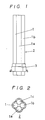
- Figs. 1 and 2 are a typical, basic example of those variations. Then, the following description is made by referring to the example shown in Figs. 1 and 2.
- a collective tubular casing which is generally designated by 2
- the air chamber 3 may be partitioned separately for each of the tubes as shown in Figs.
- the collective tubular casing 2 shown in Figs. 1 and 2 may have many possible variations as shown in Figs. 3 through 10. In Figs. 3, it is configured to include two tubes, as designated by 4.
- the variation 5 in Fig. 4 includes three tubes arranged in a triangular form.
- Fig. 5 shows a variation 6 in which five tubes are arranged.
- the variation 7 shown in Fig. 6 six tubes are used with one center tube surrounded by the five tubes.
- the variation 8 in Fig. 7 also uses six tubes, which are arranged in a triangular form.
- Fig. 9 shows a varied configuration 10, which also includes six tubes arranged in a hexagonal form.
- the variation 11 in Fig. 10 includes nine tubes arranged in a square form.
- those tubes determine the total diameter or area in cross section of a single tubular casing. Therefore, the total diameter may be increased by increasing the number of individual tubes, which may be more than nine tubes.
- those tubes should be configured geometrically so that the collective tubular casing provides equilibrium and positional stability when it is actually installed deep in water.
- the air chamber 3 includes separate air supply compartments, the number of which corresponds to the number of the individual tubes 1, 1a,1b, 1c making up the tubular casing and each of which communicates with the corresponding tube.
- Those air supply compartments are enclosed by an outer jacket 12 which is equipped with a top end plate 13.
- the outer jacket 12 is hermetically mounted around the individual tubes collectively.
- Each of the air supply compartments is formed by cylindrical partitions 14 and 15, which are concentrically spaced apart from each other and inserted between the outer jacket 12 and its corresponding tube.
- the cylindrical partition 14 has an air communicating aperture 16 at the upper portion while the partition 15 has an air communication aperture 17 at the lower portion.
- the gap 22 formed between the outer jacket 12 and partition 14, and the gap 23 formed between the partitions 14 and 15 communicate with each other through the aperture 16.
- the gap 23 and the gap 18 formed between the partition 15 and the corresponding tube communicate with each other through the aperture 17.
- Air communication between the gap 18 and the corresponding tube is made through windows 19, 19b, 19c which are made in the tube.
- Each of the air supply compartments has an air inlet port, through which, as indicated by an arrow 21, air is supplied under pressure into the outer gap 22 from an air suction hose 20, 20b, 20c which connects with any external compressed air supply source, such as air compressor.
- the air under pressure through the inlet port is drawn into the gap 22 and then through the aperture 16 into the gap 23. During the time that the air supply continues to take place, the air is gathering upwardly inside the gaps 22 and 23 and the water level inside the tube is gradually being lowered under the action of the air.
- the air filled inside the gaps 22 and 23 is made to flow in the direction of an arrow 25, passing through the aperture 17 to flow in the direction of an arrow 26 and then through the aperture 19b to flow into the tube as indicated by an arow 27.
- the air flow into the tube then forms into a single air mass like a bullet shape 28, and is rising through the tube. As the air mass is rising, the portion of water above the air mass is boosted, and the portion of water located below the air mass is placed under the suction action of the air mass and is pumped up.
- the jets of water produce water rings over the surface, diffusing effectively in radial directions.
- a large sphere of convection is formed around the collective tubular casing, and water circulates between the surface and the depth (such as a depth of 20 m and more). This enhances the capability of the single collective tubular casing, allowing it to handle 10 million tons of water at one site.
- Fig. 13 shows the variation of the air chamber 3 in Figs. 11 and 12, which provides a common air chamber for all of the individual tubes 1, 1a, 1b and 1c.
- a single air supply room is provided below the bottom ends of those tubes, and communicates with each of the tubes.
- the flow of air supplied through the apertures 19b, etc. gathers upwardly in a single area which has a diameter substantially equal to that of a single tubular casing.
- the air flow is distributed into each individual tube, rising through it toward the surface and forming an air mass.
- water is drawn into the single area under the suction action of those air masses, and is also distributed into each tube. Thereafter, the same thing occurs as described for the air chambers in Figs. 11 and 12.
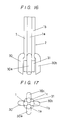
- FIG. 16 A varied form of the collective tubular casing described in the preceding embodiment is shown in Figs. 16 through 18, which includes an air supply chamber whose construction differs from the preceding ones, and water suction pipes in addition to those tubes described above.
- the collective tubular casing includes the same number of individual air and water passage tubes (four), but may include additional tubes.
- the collective tubular casing 2 includes small-diameter individual tubes combined together, a common air chamber 31 which is located below the tubes and communicates with each of the tubes, and water suction pipes 30, 30a, 30b, and 30c each of which is connected with the corresponding tube.
- Fig. 16 A varied form of the collective tubular casing described in the preceding embodiment is shown in Figs. 16 through 18, which includes an air supply chamber whose construction differs from the preceding ones, and water suction pipes in addition to those tubes described above.
- the collective tubular casing includes the same number of individual air and water passage tubes (four), but may include additional tubes.
- the collective tubular casing 2
- the air chamber 31 includes an outer jacket 32 closed at the top, an inner cylindrical partition 33 open at the top and closed at the bottom, and tubular passage 34 which extends through the closed top of the outer jacket 32 and allows air to flow therethrough into the individual tubes.
- Those parts 32, 33 and 34 are arranged concentrically at spaced relations with respect to each other.
- An compressed air is supplied from an air suction hose 35 into the air chamber 31 as indicated by an arrow 36, and gathers upwardly in the air chamber 31. As the air supply is increasing, it acts on the water in the air chamber, depressing its level down to the position where the bottom open end of the tubular passage 34 is located.
- the air and water passages making up the tubular casing may be varied as shown in Figs. 14 and 15.
- Fig. 14 the interior of a larger-diameter tubular caising 46 is equally divided into three separate portions 47 which are formed like an are shape, and three smaller-diameter tubes 48, 48a, and 48b forming the air and water passages are provided longitudinally.
- Fig. 15 three smaller-diameter tubes 49, 49a, and 49b are bound by ropes 50, forming a collective tubular casing.
- the air chamber as described in the preceding embodiments may be used.
- a further variation of the collective tubular casing shown in Figs. 19 and 20 includes an air chamber that is located between four individual small-bore diameter water passage tubes and an additional water suction pipe that extends below the air chamber.
- the air chamber 53 is formed below the lower ends of the individual water passage tubes 54, 54a, 54b, and 54c so that it can communicate with each of those tubes for supplying air under pressure, and the water suction pipe 54 extends below the air chamber, through which water is rising under the suction of the air supplied from the air chamber.
- the length of the water suction pipe may be determined, depending upon the depth of the water in which the tubular casing is actually to be installed.
- This construction described above is particularly useful in allowing deep waters, such as dam installations and lakes and marshes, to be aerated.
- the construction that includes the four tubes of 30 m and the water suction pipe of 20 m length may be used.
- This specific construction tubular casing may be installed so that the top ends of the tubes are located 5 m to 10 m deep beneath the water surface, and air may be supplied under the low atmospheric pressure equivalent to about 2 atms. Under those conditions, the portion of water which is located 50 m to 60 m deep can effectively be subjected to the aeration. The fact that air can be supplied under such low pressure allows for the use of any low-pressure air supply equipment.
- the use of the low-pressure air supply makes the total system including the other accompanying equipment less costly than using the high-pressure air supply. This also reduces any difference in the air volumetric capacity between the air chamber and the upper portions of the individual tubes. As such, the operation can continue smoothly.
- Figs. 22 and 23 illustrate a two-stage construction according to another embodiment of the present invention, which consists of an upper collective tubular casing and a lower collective tubular casing that are connected together for the air and water communication.
- the lower collective tubular casing 58 which consists of individual tubes 57, 57a, 57b, and 57c each of a diameter of 40cm, it includes a lower air chamber 55 located below the lower collective tubular casing 58 and connected thereto, an air joining tubing 56 located above the lower air chamber 55 and where air from the air chamber gathers, and a water-flow regulating tubing 59 located above the lower collective tubular casing 58 and connected thereto.
- the upper collective tubular casing 63 which consists of individual tubes 62, 62a, 62b, and 62c each of a diameter of 45 cm, it includes an upper air chamber 60 located below the upper collective tubular casing 63 and connected to the top end of the lower water-flow regulating tube 59, an air joining tubing 61 located above the upper air chamber 60 and connected thereto, and a water-flow regulating tubing 64 located above the upper tubular casing 63 and connected thereto.
- each individual tube in the lower collective tubular casing 58 has a diameter of 40cm, and each of those in the upper collective tubular casing 63 has a diameter of 45cm.
- the diameter may be varied, depending upon the installation requirements. For example, the diameter may have the range of between the shown diameters and two times those diameters.
- the construction shown in Figs. 22 and 23 is designed to be installed in a dam that is 50m or more deep, for example. Therefore, each of the upper and lower colletivie tubular casings 58 and 63 has a length of about 20m,and each of the associated tubes such as the water-flow regulating tube has a length of between 3m and 5m.
- Each of the air joining tubes 56 and 61 receives air which is supplied from the corresponding air chamber at regular intervals, and provides an area that allows the air gather together, forming a single air mass or bubble. This air mass is divided through a divider plate 65 into four air masses or bubbles, each of which is rising through the corresponding individual tube.
- a frusto-conical separator guide 66 is located below the upper air chamber 60, and a horizontal plate 67 is provided below the separator guide 66.
- the separator guide 66 includes inner and outer guides having like frusto-conical shapes, which are arranged at specific intervals. Those inner and outer guides separate air from water, allowing air to be introduced into the air chamber and delivering water onto the horizontal plate 67. Therefore, the water which is drawn through inlet ports 68 into the lower collective tubular casing 58 as indicated by an arrow 72 is being raised through the individual tubes toward the separator guide 66, as indicated by an arrow 73.
- Fig. 25 is a variation of the construction shown in Fig. 22, which includes an additional collective tubular casing added above the two-stage construction.
- the lower collective tubular casing 78 includes a lower air chamber 76 below it, an air joining tube 77 connected between the lower air chamber 76 and the tubular casing 78, and a water-flow regulating tube 79 connected to the tubular casing 78.
- the intermediate collective tubular casing 83 includes an intermediate air chamber 81 connected to both the water-flow regulating tube 79 through a separator guide 80 and to the intermediate tubular casing 83, an air joining the tube 82 conneted to the intermediate air chamber 81, and a water-flow regulating tube 84 connected to the intermediate tubular casing 83.
- a separator guide 85 is provided between the intermediate water-flow regulating tube 84 and the tubular casing 88, and an upper air chamber 86 is connected through the separator guide 85 to the tubular casing 88. It further includes an air joining tube 87 above the air chamber 86, and a water flow regulating tube 89 above and the tubular casing 88.
- an air under pressure is supplied through an air supply hose 90 into the lower air chamber 76 as indicated by an arrow 91, from which the air is delivered into the lower air joining tube 77 at regular intervals, as described in the preceding embodiments.
- the air gathers together within the air joining tube 77, forming a single, large air mass or bubble.
- This air mass is rising through the air joining tube 77, from which it is divided into four air bubbles.
- Those air bubbles are introduced into the corresponding individual tubes within the lower collective tubular casing 78 (four tubes are shown for the example), and are rising through the individual tubes as indicated by an arrow 92.
- the air bubbles within the air chamber 81 are further rising and enters the air joining tube 82, as indicated by an arrow 97, through which the air bubbles are introduced into the intermediate collective tubular casing 83, through which they are rising as indicated by an arrow 98.
- the air bubbles enter the separator guide 85 via the water-flow regulating tube 84, as indicated by an arrow 99, where the air bubbles and the water are separated, allowing the air bubbles to enter the upper air chamber 86 and allowing the water to disperse against the horizontal plate 100 in the radial directions as indicated by an arrow 101.
- the air bubbles within the unpper air chamber 86 are rising, as indicated by an arrow 102, entering the air joining tube 87 through which they are further rising through the upper collective tubular casing 88 as indicated by an arrow 103 and then through the flow-regulating tube 89.
- the water is dispersed in the radial directions on the surface, as indicated by an arrow 104.
- water is drawn through inlet ports 105 into the tubular casing 83 under the action of the air bubbles, as indicated by an arrow 106, and is rising together with the rising air bubbles as indicated by an arrow 98.
- the air bubbles and the water are separated, allowing the water to strike down against the horizontal plate 100 and disperse in the radial directions as described before.
- the water which is drawn through the inlet ports 107 into the upper collective tubular casing 88 as indicated by an arrow 108 is rising through the tubular casing 88 as indicated by an arrow 103, arriving at the flow-regulating tube 89 from which the water is jetted and dispersed in the radial directions as indicated by an arrow 104.
- the construction described above provides three circulating flows around the three different collective tubular casings, one being caused by the water drawn through the inlet ports 93 and dispersed along the horizontal plate 96 in the radial direction, the second being caused by the water drawn through the inlet ports 105 and dispersed along the horizontal plate 100 in the radial directions, and the third being caused by the water drawn through the inlet ports 107 and jetted through the flow-regulating tube 89 and dispersed in the radial directions.
- the quality of the waters around those three different areas can be improved so that they can contain more oxygen.
- This has the accompanying effect of promoting the growth of fishes and other microbioorganisms living in the waters. This also allows the microorganisms to be processed.
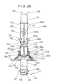
- Fig. 26 provides a combination of a single colletive tubular casing and an air diffusion tubing located below the tubular casing
- the construction provided by the embodiment includes a collective tubular casing 114 and an air diffusion tubing 109.
- the air diffusion tubing 109 is located below the colletive tubular casing 114, and includes an air diffusing pipe 110 which is disposed below the air diffusing tubing 109 across it.
- a separator guide 111 is located above the air diffusion tubing 109, and includes frusto-conical guide members 112a, 112b, 112c and 112d which are spaced away from each other.
- An air chamber 112 above the air diffusion tubing 109 is connected to the air diffusion tubing 109 and to an air joining tubing 113 located above the air chamber 112, above which the collective tubular casing 114 is located.
- the collective tubular casing 114 is connected to a flow-regulating tubing 115 which is located above it. All of the above-mentioned parts are communicated internally with each other, allowing the air and water to be rising through the passages formed by the different parts.
- An air under pressure is supplied through an air supply hose 116 into the air diffusing pipe 110, as indicated by an arrow 117.
- the air is rising in minute air bubbles as indicated by an arrow 118, entering the air diffusion tubing 109 above the air diffusion pipe 110.
- Those minute air bubbles are further rising through the air diffusion tubing 109, as indicated by an arrow 119, and water is drawn through inlet ports 120 into the air diffusing tubing 109 under the action of the air bubbles, as indicated by an arrow 121.
- the water and air bubbles are mixed together, and the oxygen contained in the air bubbles dissolves into the water.
- the water-air mixture is rising as indicated by an arrow 124, and enters the separator guide 111, where the water and air are separated.
- the water goes down onto the frusto-conical guide members 112a, 112b, 112c, and 112d within the separator guide 111, as indicated by an arrow 122. Striking the guide members, the water is guided along those members onto the horizontal plate 123 and dispersed along the plate 123 in the radial directions as indicated by an arrow 125.
- the air, which is separated from the water, is rising and is introduced into the outer air room 126 within the air chamber 112.
- the air gathers in the intermediate and inner air rooms 126a and 126b, depressing the water present inside the air chamber 112 down to the level where the communicating port 127 between the inner and intermediate air rooms is located.
- the air present in the air chamber 112 is delivered at one time through the commnicating ports 127, 128 and 129 into the air joining tubing 113, as indicated by an arrow 130.
- a single, large air mass or bubble 131 can be formed within the air joining tube 113, and is rising through the tube 113 as indicated by an arrow 132.
- the air bubble 131 reaches the air divider plate 133, through which the air bubble is divided into smaller air bubbles, which are rising through the corresponding tubes 134, 134a in the collective tubular casing 114, as indicated by arrows 135 and 135a.
- the air bubbles are rising through the tubes so that they closely contact the inner wall of the tube, as indicated by the dot-dash lines 136 and 136a, they develop a vacuum or negative pressure behind them, drawing water under the suction of the vacuum through the inlet ports 137 and 137a into the tubes, as indicated by arrows 138 and 138a.
- the water drawn in the tubes is being raised under the action of the preceiding air bubbles, and is jetted through the flow regulating tube 115, dispersing on the surface in the radial directions as indicated by an arrow 139.
- two circulating flows are produced, one around the air diffusion tube 109 and the other around the collective tubular casing 114.
- the air diffusing tube below the collective tubular casing can atomize the air introduced, and the oxygen contained in the air can dissolve into the water with improved efficiency.
- This embodiment is more effective when it is used for the deep waters such as dams, etc., in order to increase the amount of oxygen to be contained in the water that is located deep, thereby improving its quality.
- the water that is located on the surface and contains much oxygen can go down into the deep by the circulating flow of a jet of water that is caused by the upper collective tubular casing, and meet the water portion that is located and contains less oxygen.
- the quality of the water can be improved without relying on the oxygen contained in the air supply.
- FIG. 21 shows the example in which several tubular casings 2 are to be installed at appropriate intervals in a sea port or bay in the cold climate regions.
- any of those collective tubular casings is installed, it is placed in its vertical position deep into the water, with its bottom end located near to the bottom of the water and its top end located about 5 m deep beneath the water surface. Then, a compresed air is introduced into the air chamber from any external air supply source such as air compressor.
- the air gathers upwardly in the air chamber and then is released from the air chamber, flowing into the individual tubular passages usually in the form of tubes. As the air is rising through each of the tubular passages, it forms into an air mass like a bullet shape. Following the first air mass, another air mass is formed in the same manner as described above. Thus, the portion of water which is sandwiched between the preceding and following air masses is rising through the tubular passages under both the suction and boost actions of the air masses. That portion of water located near the bottom contains less oxygen, and is rising toward the surface, from which it is jetted and diffused in radial directions as indicated by an arrow 52.
- the portion of water located on the surface and containing enough oxygen is in turn being lowered toward the bottom under the action of the produced convection. Exchanging those portions of water between the bottom and surface improves the oxygen content in the water rapidly.
- This water circulation by convection also provides an effective anti-freezing means. Since the portion of water located near the bottom is usually maintained to a temperature of 4°C at the lowerst, the water surface can also be maintained to the temperature of 4 °C or higher by causing the water to circulate by convection between the bottom and surface.
Landscapes
- Chemical & Material Sciences (AREA)
- Chemical Kinetics & Catalysis (AREA)
- Life Sciences & Earth Sciences (AREA)
- Engineering & Computer Science (AREA)
- General Engineering & Computer Science (AREA)
- Organic Chemistry (AREA)
- Biodiversity & Conservation Biology (AREA)
- Environmental Sciences (AREA)
- Hydrology & Water Resources (AREA)
- Environmental & Geological Engineering (AREA)
- Water Supply & Treatment (AREA)
- Animal Husbandry (AREA)
- Microbiology (AREA)
- Marine Sciences & Fisheries (AREA)
- Mechanical Engineering (AREA)
- Civil Engineering (AREA)
- Structural Engineering (AREA)
- Aeration Devices For Treatment Of Activated Polluted Sludge (AREA)
Priority Applications (2)
| Application Number | Priority Date | Filing Date | Title |
|---|---|---|---|
| EP19850307535 EP0220345B1 (fr) | 1985-10-18 | 1985-10-18 | Appareil pour l'aération d'eau |
| DE8585307535T DE3582069D1 (de) | 1985-10-18 | 1985-10-18 | Wasserbeluefter. |
Applications Claiming Priority (1)
| Application Number | Priority Date | Filing Date | Title |
|---|---|---|---|
| EP19850307535 EP0220345B1 (fr) | 1985-10-18 | 1985-10-18 | Appareil pour l'aération d'eau |
Publications (2)
| Publication Number | Publication Date |
|---|---|
| EP0220345A1 true EP0220345A1 (fr) | 1987-05-06 |
| EP0220345B1 EP0220345B1 (fr) | 1991-03-06 |
Family
ID=8194406
Family Applications (1)
| Application Number | Title | Priority Date | Filing Date |
|---|---|---|---|
| EP19850307535 Expired - Lifetime EP0220345B1 (fr) | 1985-10-18 | 1985-10-18 | Appareil pour l'aération d'eau |
Country Status (2)
| Country | Link |
|---|---|
| EP (1) | EP0220345B1 (fr) |
| DE (1) | DE3582069D1 (fr) |
Cited By (7)
| Publication number | Priority date | Publication date | Assignee | Title |
|---|---|---|---|---|
| EP0325337A3 (en) * | 1988-01-20 | 1989-10-25 | Gist-Brocades N.V. | Startup openings in a three-phase gaslift loop reactor |
| EP0366317A1 (fr) * | 1988-10-13 | 1990-05-02 | Kaiyo Kogyo Kabushiki Kaisha | Procédé et dispositif pour modifier la qualité d'une grande quantité d'eau |
| US5227056A (en) * | 1989-08-03 | 1993-07-13 | Kaiyo Kogyo Kabushiki Kaisha | Apparatus for improving the quality of a large amount of water and the quantity of dissolved oxygen therein |
| US5256309A (en) * | 1989-08-03 | 1993-10-26 | Kaiyo Kogyo Kabushiki Kaisha | Method of improving the quality of large amount of water, and quantity of dissolved oxygen therein |
| WO2003064017A1 (fr) * | 2002-01-28 | 2003-08-07 | Anthony Gibson Wynes | Appareil de melange |
| CN108166469A (zh) * | 2018-01-30 | 2018-06-15 | 长春华普大通防冰工程技术有限公司 | 水利水电工程防冰系统 |
| CN114467833A (zh) * | 2021-12-24 | 2022-05-13 | 何雷 | 一种水产品运输用物流箱 |
Citations (5)
| Publication number | Priority date | Publication date | Assignee | Title |
|---|---|---|---|---|
| US3148509A (en) * | 1960-10-24 | 1964-09-15 | Pneumatic Breakwaters Ltd | Wave reduction, de-icing and destratification apparatus |
| US4231863A (en) * | 1979-04-26 | 1980-11-04 | Sutphin Eldon M | Method and apparatus for treating water |
| US4293506A (en) * | 1979-01-15 | 1981-10-06 | Atara Corporation | Liquid circulating device |
| US4436675A (en) * | 1981-10-26 | 1984-03-13 | Kaiyo Kogyo Co., Ltd. | Multistage water purification apparatus |
| FR2557559A1 (fr) * | 1984-01-04 | 1985-07-05 | Magyar Asvanyolaj Es Foeldgaz | Procede et dispositif pour faire circuler un liquide a l'aide de gaz |
-
1985
- 1985-10-18 EP EP19850307535 patent/EP0220345B1/fr not_active Expired - Lifetime
- 1985-10-18 DE DE8585307535T patent/DE3582069D1/de not_active Expired - Fee Related
Patent Citations (5)
| Publication number | Priority date | Publication date | Assignee | Title |
|---|---|---|---|---|
| US3148509A (en) * | 1960-10-24 | 1964-09-15 | Pneumatic Breakwaters Ltd | Wave reduction, de-icing and destratification apparatus |
| US4293506A (en) * | 1979-01-15 | 1981-10-06 | Atara Corporation | Liquid circulating device |
| US4231863A (en) * | 1979-04-26 | 1980-11-04 | Sutphin Eldon M | Method and apparatus for treating water |
| US4436675A (en) * | 1981-10-26 | 1984-03-13 | Kaiyo Kogyo Co., Ltd. | Multistage water purification apparatus |
| FR2557559A1 (fr) * | 1984-01-04 | 1985-07-05 | Magyar Asvanyolaj Es Foeldgaz | Procede et dispositif pour faire circuler un liquide a l'aide de gaz |
Cited By (8)
| Publication number | Priority date | Publication date | Assignee | Title |
|---|---|---|---|---|
| EP0325337A3 (en) * | 1988-01-20 | 1989-10-25 | Gist-Brocades N.V. | Startup openings in a three-phase gaslift loop reactor |
| EP0366317A1 (fr) * | 1988-10-13 | 1990-05-02 | Kaiyo Kogyo Kabushiki Kaisha | Procédé et dispositif pour modifier la qualité d'une grande quantité d'eau |
| US5227056A (en) * | 1989-08-03 | 1993-07-13 | Kaiyo Kogyo Kabushiki Kaisha | Apparatus for improving the quality of a large amount of water and the quantity of dissolved oxygen therein |
| US5256309A (en) * | 1989-08-03 | 1993-10-26 | Kaiyo Kogyo Kabushiki Kaisha | Method of improving the quality of large amount of water, and quantity of dissolved oxygen therein |
| WO2003064017A1 (fr) * | 2002-01-28 | 2003-08-07 | Anthony Gibson Wynes | Appareil de melange |
| US7240897B2 (en) | 2002-01-28 | 2007-07-10 | Wynes Anthony G | Mixing apparatus |
| CN108166469A (zh) * | 2018-01-30 | 2018-06-15 | 长春华普大通防冰工程技术有限公司 | 水利水电工程防冰系统 |
| CN114467833A (zh) * | 2021-12-24 | 2022-05-13 | 何雷 | 一种水产品运输用物流箱 |
Also Published As
| Publication number | Publication date |
|---|---|
| DE3582069D1 (de) | 1991-04-11 |
| EP0220345B1 (fr) | 1991-03-06 |
Similar Documents
| Publication | Publication Date | Title |
|---|---|---|
| US4906363A (en) | Water aeration apparatus | |
| US7137620B2 (en) | Diffuser and an aeration apparatus equipped with such a diffuser | |
| EP0220345B1 (fr) | Appareil pour l'aération d'eau | |
| US7954791B2 (en) | Fine bubble airlift device | |
| US4436675A (en) | Multistage water purification apparatus | |
| US5421999A (en) | Floating nitrification reactor in a treatment pond | |
| AU2022273489B2 (en) | Fish farming cage utilizing live biomass as driving force for water exchange | |
| JPH01111494A (ja) | 連設型間けつ空気揚水筒 | |
| EP0606432B1 (fr) | Reacteur | |
| US4879046A (en) | Local water cleaning method for use in consecutive water areas | |
| JPH10229781A (ja) | 水中散気方法およびその装置 | |
| US6582612B1 (en) | Plankton mitigation system | |
| CN218345269U (zh) | 一种多层曝气反应器 | |
| JPH07275884A (ja) | 大容量深水曝気装置 | |
| JPS6339315B2 (fr) | ||
| KR950002539B1 (ko) | 천수역(淺水域)에 있어서 정수방법 및 장치 | |
| EP0557630A1 (fr) | Système de circulation totale d'eau pour zones d'eau peu profondes | |
| JPS62221497A (ja) | 散気式無終端水路水槽 | |
| Hargreaves et al. | Design and construction of degassing units for catfish hatcheries | |
| CN1017139B (zh) | 水域曝气装置 | |
| KR890004209Y1 (ko) | 양수장치 | |
| AU665266B2 (en) | A reactor | |
| JPH05288198A (ja) | 複合揚水方法及び装置 | |
| JP2676048B2 (ja) | 複合多段揚水装置 | |
| JPH039839Y2 (fr) |
Legal Events
| Date | Code | Title | Description |
|---|---|---|---|
| PUAI | Public reference made under article 153(3) epc to a published international application that has entered the european phase |
Free format text: ORIGINAL CODE: 0009012 |
|
| AK | Designated contracting states |
Kind code of ref document: A1 Designated state(s): DE FR GB |
|
| 17P | Request for examination filed |
Effective date: 19870730 |
|
| 17Q | First examination report despatched |
Effective date: 19880808 |
|
| GRAA | (expected) grant |
Free format text: ORIGINAL CODE: 0009210 |
|
| AK | Designated contracting states |
Kind code of ref document: B1 Designated state(s): DE FR GB |
|
| REF | Corresponds to: |
Ref document number: 3582069 Country of ref document: DE Date of ref document: 19910411 |
|
| ET | Fr: translation filed | ||
| PLBE | No opposition filed within time limit |
Free format text: ORIGINAL CODE: 0009261 |
|
| STAA | Information on the status of an ep patent application or granted ep patent |
Free format text: STATUS: NO OPPOSITION FILED WITHIN TIME LIMIT |
|
| 26N | No opposition filed | ||
| PGFP | Annual fee paid to national office [announced via postgrant information from national office to epo] |
Ref country code: GB Payment date: 19951009 Year of fee payment: 11 |
|
| PGFP | Annual fee paid to national office [announced via postgrant information from national office to epo] |
Ref country code: FR Payment date: 19951010 Year of fee payment: 11 |
|
| PGFP | Annual fee paid to national office [announced via postgrant information from national office to epo] |
Ref country code: DE Payment date: 19951026 Year of fee payment: 11 |
|
| PG25 | Lapsed in a contracting state [announced via postgrant information from national office to epo] |
Ref country code: GB Effective date: 19961018 |
|
| GBPC | Gb: european patent ceased through non-payment of renewal fee |
Effective date: 19961018 |
|
| PG25 | Lapsed in a contracting state [announced via postgrant information from national office to epo] |
Ref country code: FR Effective date: 19970630 |
|
| PG25 | Lapsed in a contracting state [announced via postgrant information from national office to epo] |
Ref country code: DE Effective date: 19970701 |
|
| REG | Reference to a national code |
Ref country code: FR Ref legal event code: ST |