EP0220428A2 - Electrical connection devices - Google Patents
Electrical connection devices Download PDFInfo
- Publication number
- EP0220428A2 EP0220428A2 EP86112044A EP86112044A EP0220428A2 EP 0220428 A2 EP0220428 A2 EP 0220428A2 EP 86112044 A EP86112044 A EP 86112044A EP 86112044 A EP86112044 A EP 86112044A EP 0220428 A2 EP0220428 A2 EP 0220428A2
- Authority
- EP
- European Patent Office
- Prior art keywords
- module
- cable
- fixed member
- outer side
- side face
- Prior art date
- Legal status (The legal status is an assumption and is not a legal conclusion. Google has not performed a legal analysis and makes no representation as to the accuracy of the status listed.)
- Pending
Links
Images

Classifications
-
- H—ELECTRICITY
- H02—GENERATION; CONVERSION OR DISTRIBUTION OF ELECTRIC POWER
- H02G—INSTALLATION OF ELECTRIC CABLES OR LINES, OR OF COMBINED OPTICAL AND ELECTRIC CABLES OR LINES
- H02G3/00—Installations of electric cables or lines or protective tubing therefor in or on buildings, equivalent structures or vehicles
- H02G3/02—Details
- H02G3/08—Distribution boxes; Connection or junction boxes
- H02G3/18—Distribution boxes; Connection or junction boxes providing line outlets
- H02G3/185—Floor outlets and access cups
Definitions
- This invention relates to connection devices such as junction boxes and the like for use with flat cables for power distribution such as the type designed for undercarpet use.
- connection system which is simple and effective to use in situ and which is nevertheless adaptable to a variety of different circumstances.
- British Patent Application 84 24281 discloses a connection device in the form of a pedestal on which can be mounted a standard socket outlet unit.
- the pedestal is formed by a base member across which the cable is laid, an upper clamping member secured to the base member, and an insulative separating plate.
- the separating plate is inserted between conductive elements of the cable, notably beneath the earthing screen and above the current-carrying conductors.
- Contact with the current-carrying conductors is made by means of respective insulation displacement contact (IDC) means on a base member, which are joined to respective screw terminals.
- the separating plate stops the IDC means penetrating too far.
- a further IDC means on the clamping member connects with the earthing screen.
- the socket outlet is connected up with short lengths of electric wire, familiar to the electrician.
- connection device is of great practicality but there are instances where it would be desirable to provide other sockets closely adjacent to the power socket, such as telephone or data outlets, or to enable connection of further power outlets by flat cable to an existing outlet.
- an electrical connection housing comprising a fixed member adapted to be secured to a flat surface and having an outer side face for receiving a module member, and a module member having an inner side face conforming to the outer side face of the fixed member, the module member also having protruding engagement means extending under the outer side face of the fixed member to be retained between the fixed member and the flat surface when the fixed member is fastened to the surface, whereby the module member is located in position without being directly secured to the surface, the module member providing a housing for a selectable type of connector member.
- the module member preferably has an outer side face of the same shape as the outer side face of the fixed member.
- the invention provides an insulation displacement contact assembly comprising a threaded bolt having a head with rotatable formations thereon, a cup-shaped insulation displacement contact on the end of the bolt and having insulation displacement portions on its rim pointing away from the head, and means retaining the contact on the bolt.
- the invention provides an electrical connection device for connection to a flat conductor strip, the device comprising a housing block and a contact assembly, the contact assembly including a plate, a bolt threaded through the plate, and a cup-shaped insulation displacement contact on the end of the bolt and having insulation displacement portions on its rim, and the housing block having a first slot for receiving a portion of flat cable, and a second slot spaced from and parallel to the first for receiving the plate of the contact assembly.
- This invention thus provides a connection device including a power socket and other sockets closely adjacent thereto, such as a telephone outlet, a data outlet or an additional power outlet.
- This invention is particularly suitable for undercarpet systems.
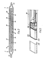
- the undercarpet cable 10 shown in Figure 2 will first be described. it has a live conductor 12 and a neutral conductor 14. For use on 240 volts with a 30 amp current rating, these conductors are preferably of copper strip about 0.25 mm thick and about 20 mm wide. These conductors 12,14 are sandwiched between two flat films or strips 16,18 which form an inner insulation sheath 15 and are about 60-65 mm wide.
- the strips 16,18 are each conveniently a lamination of a polyester layer of about 0.06 mm thickness on the outer side away from the conductors, a fire retardant vinyl layer also of about 0.1 mm, and a heat-sealable adhesive layer on the innermost side.
- the total thickness of each strip 16,18 is about 0.15 mm.
- the conductors 12,14 are placed side by side on the lower strip 16 with a space of the order of 10 mm between them, and the upper strip 18 is then applied.
- the composite is then passed through shaped heat-sealing rollers to cause the conductors to be fully bonded to the sheath, and the two layers of the sheath to be bonded to each other in the regions where there is no conductor. These regions comprise a central region 20 between the conductors, and edge regions 22 to either side of the conductors.
- the live and neutral conductors 12,14 are in this way formed into a sealed insulated inner package.
- the earthing conductor 26 has a width approximately equal to the width of the whole package and acts as an electromagnetic screen, as well as assisting effective heat dissipation and providing a safety function in the event that the cable is penetrated by a foreign body (e.g. a nail).
- the earthing conductor 26 can normally be about half the thickness of the live and neutral conductors 12,14.
- the earthing conductor 26 should preferably not be bonded to the package 24 but is simply loosely laid on it, and if it is bonded to the conductor package, it should be sufficiently lightly bonded to be readily separable from it by hand.
- An outer insulation jacket or sheath 28 is now formed tightly around the combination of the package 24 and earthing conductor 26, by two flat strips 30,32 which are of the same plastics lamination as the strips 16,18, only about 20 mm wider.
- the edges 34 of the strips 30,32 are then heat sealingly bonded to each other to form a sealed sheath.
- the earthing conductor 26 is bonded to the upper strip 32 and the package 24 can be lightly bonded, for example at intermittent bands along the cable, to the lower strip 30.
- the completed cable is then typically about 80-85 mm wide and 1 mm thick.
- the sheath 28 has the effect of sealing the edge portion of the cable construction, and attaching the edge of the earthing conductor 26 to the edge of the package 24 to hold them together.
- the outer sheath 28 preferably carries indications, e.g. by colour coding, as to which is the top and which is the live conductor. If desired a second earthing conductor can be placed beneath the conductor package to provide further electrical and mechanical protection and also to enable the cable to be used either way up. This enables the cable to be made to change direction by a simple fold.
- the cable is installed underneath the carpet in an office or like environment.
- the cable is laid on the floor and covered by a steel tape which provides mechanical protection and which is secured to the floor by adhesive tape.
- the carpet can then be replaced over the cable.
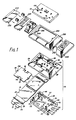
- FIG. 1 illustrates the mounting of a socket outlet 40 on the cable 10.
- a socket outlet 40 is a standard socket outlet appropriate to the type of plug connector to be received, and in the United Kingdom can be a twin socket outlet in accordance with the relevant British Standard (BS 1363) as designed for flush or surface wall mounting. No special socket outlet unit is required.
- the socket outlet will normally have screw connectors designed to receive an input power cable of conventional type.
- the base unit 52 is of generally rectangular shape and has a broad transverse recess 58 forming a surface across which the flat cable 10 is laid.
- the end pillars 60 to either side of this recess 58 contain various moulded bores. These include two bores 62 near two opposed corners of the base unit for receiving fixing screws, if the pedestal is to be mounted on a wooden floor, or masonary or concrete fixing devices for other floors.
- bores 64 which each accommodate a threaded bush 66 to receive a bolt (not shown) which secures the clamp unit 54 to the base unit.
- the contact 76 comprises a square plate the corners of which are bent upwards as shown to provide four sharp contact points, capable of penetrating the insulating sheath of the cable 10 to make good electrical contact with the live and neutral conductors 12 and 14.
- the clamp unit 54 is designed to fit over and around the base unit 52 and with the assistance of the plate 56 to press the package 24 in the cable 10 down onto the IDC contacts 76 so that proper contact is made.
- the clamp unit 54 of the same general shape as the base unit but has a central aperture 78 for receiving the rear of the socket outside 40 and associated wiring, and also a larger flange 80 which bears against the floor (or may be relieved to receive the edge of the carpet).
- Four bores 82 accommodate the bolts (not shown) which are received in the threaded bushes 66 in the base unit. When the bolts are tightened the necessary clamping force is applied to the cable.
- the bolts are of the type which take a hexagonal Allen key so that they can provide a large clamping force.
- the lower end of the post 86 is designed to form an insulation displacement contact which provides an earth termination to the earth conductor 26 in the cable 10.
- the upper end of the post 86 is provided with a screw terminal 88 similar to the screw terminals 72 for the live and neutral conductors. Further bores 90 are aligned above the four possible positions of the terminal posts 72, and open into the aperture 78.
- the cable is laid across the floor and the desired position for an outlet socket is chosen. A hole of appropriate size is made in the carpet.
- the electrician has to gain access to the cable conductors. This he does with a sharp knife by slitting or cutting off the edges 34 of the outer sheath 28 in the region that will be lying over the recess 58.
- the line of the cut is shown at X in Figure 2 and by the dashed lines X in Figure 1.
- making these cuts in the right place is very easy.
- the earthing conductor 26 is at least as wide as the conductor package 24.
- all the electrician has to do is to feel for the edge of the earthing conductor 26, and to cut alongside it. In this way he removes the edge portions 34 which bond the two halves of the outer sheath together, but he is in no danger of violating the live and neutral conductor package 24.
- the earthing conductor 26 was not bonded to the conductor package 24 or at least not firmly bonded.
- the top part consists of the top outer insulation strip 32 and the earthing conductor 26
- the bottom part consists of the bottom outer insulating strip 30 and the conductor package 24, the latter containing the live and neutral conductors 12 and 14 in the inner insulating sheath 15.
- the electrician takes the insulating plate 56, which is of the same general shape as the recess 58 across which the cable lies.
- the electrician slides this plate between the two separated parts of the cable and places it over the recess 58.
- the clamp unit 54 is placed on top and the clamping bolts in bores 82 are tightened into bushes 66.
- the clamping force is sufficient to force the bottom part of the cable down onto the contacts 76 to cause the contact points to penetrate the insulation and make contact with the live and neutral conductors 12 and 14 respectively, and to cause the contact portion of the terminal post 86 to penetrate the earth conductor 26.
- the plate 56 has bores or recesses 92 which are aligned with the points of the contacts 76. To maintain the alignment of the plate 56, the plate has rectangular projections 94 at either end which slide into corresponding recesses 96 in the inside edges of the pillars 60.
- the base plate 52 may optionally include threaded bushes 98 at this point, in which case the plate 56 has corresponding holes 100. A bolt can then be passed through each hole 100 into the bush 98 and tightened to hold the plate 56 and hence the bottom part of the cable in place for the subsequent assembly stages.
- the plate 56 is of such a thickness that there can be no danger of the contacts 76 penetrating from the underside as far as the top surface of the plate to make contact with the earth, or the earth IDC penetrating from the upper side to make contact with the live and neutral conductors below. To assist in allowing penetration of the conductor the plate has cut-outs 102.
- the plate 56 can have appropriate instructions printed on it to assist the electrician in installing the socket outlet correctly.
- the clamp unit 54 has two threaded bushes 104 at the required spacing at either end of the aperture 78.
- Conventional fixing bolts (not shown) pass through holes 106 in the socket outlet 40 and engage in bushes 104.
- the base unit 52 has two bores 108 which receive the ends of these fixing bolts should they protrude through the clamp unit 54.
- the shroud or cover 200 is interposed between the socket outlet 40 and the clamp unit 54.
- the shroud has a configuration generally similar to the top surface of the clamp unit 54, with a central aperture 202 just smaller than the outer periphery of the socket outlet so as to be clamped between the socket outlet and the clamp unit.
- Two lips 204 are provided having apertures 206 which are positioned in line with the bushed 104 in the clamp unit, so that the bolts in holes 106 pass through the apertures 206.
- terminal posts 72 protrude through the bores 90 in the clamp unit 54, so that the screw terminals 110 are accessible from above and the wire-receiving transverse bores 112 in the terminal posts are open into the aperture 78.
- a short length of insulated wire is then run from the terminal posts to the terminals on the rear of the standard twin switched socket 40.
- the earth connection is provided by a further length of wire between the respective terminal on the socket 40 and the screw terminal 88 at the top of terminal post 86 which makes direct contact with the earth conductor 26 in the cable.
- This type of connection is familiar to electricians and so is easy to make and most unlikely to be made incorrectly.
- the pedestal 50 provides a standard fixing for the socket 40, alternative types of outlet can be used which have the same fixing parameters.
- An advantage of the system illustrated is that if it is desired to remove the socket outlet from the position in which it is installed, this can be done without difficulty. The only damage done to the cable is to make small pinpricks in the insulation.
- the same basic pedestal can be used in other different configurations. Different types of outlet sockets can be mounted by using a spacer or adaptor moulding.
- the pedestal illustrated can also be used to join two lengths of cable 10, or as a transition box to join a length of conventional supply cable to the flat cable 10.
- the pedestal When used as a junction box to join two lengths of flat cable in line, the pedestal includes four of the terminal posts 72 and associated insulation displacement contacts 76 spaced in the recess 58.
- the cable lengths are cut so as to terminate in the middle of the recess, and thus the contacts 76 at one end of the recess 58 will embed in one of the cable ends and those at the other end of the recess in the other cable end.
- the live and neutral connections are completed by short lengths of wire between the terminal posts 72, and the earth connections by a short length of wire between terminal posts 86.
- a socket 40 can be mounted on such a junction box or, if no socket is required at that point, a conventional plain blanking plate can be used. This system is particularly useful in that it enables an existing cable length terminating at a socket outlet to be extended by an additional length of cable without the need to replace the existing length with a longer length.
- the cable and pedestal cooperate to provide an extremely effective power distribution system for undercarpet use.
- the cable provides the current-carrying conductors with two layers of insulation, but is constructed so as to facilitate terminating and joining to the cable.
- the pedestal takes advantage of the cable construction and provides a simple but adaptable mounting which can be used in various configurations, namely with standard outlet sockets, or as a junction box to join two like cable lengths, or as a transition box to join the flat cable to a conventional cable, or to perform two of these functions simultaneously.
- the system is essentially as described in British Patent Application 84 24281, though with the addition of the shroud 200.
- the shroud or cover gives the added advantage of being replaceable to enable other styles of socket to be fitted, as may be used in other countries, without having to change the base and clamp unit. It also allows colour changes to be made easily and hides any unacceptable marks on the clamp unit.
- FIG. 1 includes a various modules 220, 222, 224 which can be attached to the side of the pedestal unit 50.
- Module 220 provides two telephone outlets
- module 222 has two data outlet sockets
- module 224 is designed to enable a power spur to be connected.
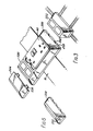
- Figure 3 shows the modules connected to the assembled central pedestal unit. The modules can be chained together except that no further modules may be added before or after a power spur module 224 because the outgoing power cable will be in the way and power cables from the spur connect directly to the power pedestal.
- FIGS 3 to 5 show how the modules are attached to the pedestal unit 50.
- the modules have the outline shape of the end part of the shroud 200, and their inner faces conform to the shape of the end part of the shroud, so as to provide a natural extension to the shroud.
- the outer face of the shroud is generally inclined downwardly and outwardly, as seen in Figures 3 and 5.
- the inner face of the module 220 has as an extension of its bottom surface two T-pieces 230. These T-pieces pass through recesses 232 in the bottom of the shroud and of the clamping unit, and stop the module from moving away from the pedestal or the preceding module, thus holding the structure in the assembled condition.
- the method of assembly of the modules onto the pedestal is best illustrated by Figure 5.
- the socket outlet 40 is first released, also releasing the shroud or cover 200.
- the modules are then abutted to the power pedestal and held captive by the cover when the cover is screwed into position.
- the module can not now be removed as the T-pieces can not be released from the cover unless the cover is lifted from the floor.
- the underside of the modules is hollow to accommodate the connector components as shown at 240 in Figure 1. If desired, recesses 242 ( Figure 3) can be provided to allow access between the module and pedestal interiors for conductor wires.
- the socket-receiving modules 220 and 222 have standard sized openings which receive telephone, data and fibre optic connectors as desired.
- Figure 3 illustrates how the telephone and data lines to the modules can be laid under the carpet, either parallel or at right angles to the run of the power cable.
- the modules 220 or 222 may sometimes be desired to use the modules 220 or 222 separately from the power outlet pedestal unit. This can be done using the link member 250 of Figure 6 which is configured like the two opposed ends of the shroud or cover 200. Two bores 252 are provided by which the link member can be secured to the floor with fastening devices.
- the power spur module 224 is slightly different in that is has no socket outlet apertures and really just provides a cover for insulation displacement contacts used to connect a spur cable.
- These contact members are illustrated in Figures 7 to 9 and comprise a nylon moulding 260 ( Figures 7 and 8) and a contact assembly 280 ( Figure 9).
- the moulding 260 is generally rectangular of about 20mm by 16mm by 13mm and essentially provides two slots, a first open slot 262 for receiving the end of a flat conductor from a selection of cable, and second through slot 264 for locating the contact assembly above the cable end.
- the contact assembly 280 comprises a flat brass plate 282 having two threaded bores 284, 286. Into one of these there is threaded a bolt 288 having a slotted head and which carries at its end a cup-shaped IDC contact 290 having eight triangular teeth 292 formed on its rim and pointing away from the head of the bolt. The end of the bolt is rivetted over as at 294 to retain the contact 290 on the bolt while allowing relative rotation of the bolt and contact. A washer 296 may assist in this.
- the assembly 290 is slid into the slot 264 in the moulding 260. This will position the contact 290 above the plane of the cable-receiving slot 262. A recess 296 may be provided beneath the contact 290.
- the bolt 288 can be tightened with the aid of a screwdriver in the head of the bolt, moving the threaded bolt downwardly through the plate 282 and forcing the teeth 292 into the cable end. A positive connection is thus made.
- the other bore 286 in the strip 282 enables a normal screw connection to be made to a short length of cable, the other end of which is terminated on one of the terminal posts 72 and 86 as appropriate.
- the contact system formed by bolt 288, cup-shaped IDC contact 290 and washer 296 may be suitable for other purposes and the terminal post 86 may be of similar design.
Landscapes
- Engineering & Computer Science (AREA)
- Architecture (AREA)
- Civil Engineering (AREA)
- Structural Engineering (AREA)
- Connector Housings Or Holding Contact Members (AREA)
Abstract
Description
- This invention relates to connection devices such as junction boxes and the like for use with flat cables for power distribution such as the type designed for undercarpet use.
- A demand exists for a connection system which is simple and effective to use in situ and which is nevertheless adaptable to a variety of different circumstances.
-
British Patent Application 84 24281 discloses a connection device in the form of a pedestal on which can be mounted a standard socket outlet unit. The pedestal is formed by a base member across which the cable is laid, an upper clamping member secured to the base member, and an insulative separating plate. The separating plate is inserted between conductive elements of the cable, notably beneath the earthing screen and above the current-carrying conductors. Contact with the current-carrying conductors is made by means of respective insulation displacement contact (IDC) means on a base member, which are joined to respective screw terminals. The separating plate stops the IDC means penetrating too far. A further IDC means on the clamping member connects with the earthing screen. The socket outlet is connected up with short lengths of electric wire, familiar to the electrician. - Such a connection device is of great practicality but there are instances where it would be desirable to provide other sockets closely adjacent to the power socket, such as telephone or data outlets, or to enable connection of further power outlets by flat cable to an existing outlet.
- According to this invention in one aspect there is provided an electrical connection housing, comprising a fixed member adapted to be secured to a flat surface and having an outer side face for receiving a module member, and a module member having an inner side face conforming to the outer side face of the fixed member, the module member also having protruding engagement means extending under the outer side face of the fixed member to be retained between the fixed member and the flat surface when the fixed member is fastened to the surface, whereby the module member is located in position without being directly secured to the surface, the module member providing a housing for a selectable type of connector member. The module member preferably has an outer side face of the same shape as the outer side face of the fixed member.
- In another aspect the invention provides an insulation displacement contact assembly comprising a threaded bolt having a head with rotatable formations thereon, a cup-shaped insulation displacement contact on the end of the bolt and having insulation displacement portions on its rim pointing away from the head, and means retaining the contact on the bolt.
- In a further aspect the invention provides an electrical connection device for connection to a flat conductor strip, the device comprising a housing block and a contact assembly, the contact assembly including a plate, a bolt threaded through the plate, and a cup-shaped insulation displacement contact on the end of the bolt and having insulation displacement portions on its rim, and the housing block having a first slot for receiving a portion of flat cable, and a second slot spaced from and parallel to the first for receiving the plate of the contact assembly.
- This invention thus provides a connection device including a power socket and other sockets closely adjacent thereto, such as a telephone outlet, a data outlet or an additional power outlet. This invention is particularly suitable for undercarpet systems.
-
- Figure 1 is an exploded perspective view of an outlet socket and its pedestal mounted on an undercarpet power cable.
- Figure 2 is a section through the cable.
- Figure 3 is a perspective view of the pedestal when assembled with associated modules.
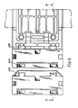
- Figure 4 is an underplan view of part of the pedestal unit and modules.
- Figure 5 is a sectional view taken on the line V-V in Figure 4.
- Figure 6 is a perspective view of a link section for joining modules in the absence of a power outlet pedestal unit.
- Figure 7 is a perspective view of a plastics ;block for housing an insulation displacement contact (IDC) in the power module.
- Figure 8 shows various views of the block of Figure 7, namely (a) a sectional view, and (b) front, (c) back, (d) top and (e) bottom views.
- Figure 9 is a side view of the IDC assembly used in the block.
- The
undercarpet cable 10 shown in Figure 2 will first be described. it has alive conductor 12 and aneutral conductor 14. For use on 240 volts with a 30 amp current rating, these conductors are preferably of copper strip about 0.25 mm thick and about 20 mm wide. Theseconductors strips inner insulation sheath 15 and are about 60-65 mm wide. Thestrips strip conductors lower strip 16 with a space of the order of 10 mm between them, and theupper strip 18 is then applied. The composite is then passed through shaped heat-sealing rollers to cause the conductors to be fully bonded to the sheath, and the two layers of the sheath to be bonded to each other in the regions where there is no conductor. These regions comprise acentral region 20 between the conductors, andedge regions 22 to either side of the conductors. The live andneutral conductors - To form the complete cable a solid copper earthing (or grounding)
conductor 26 is now placed over the conductor package. The earthing conductor has a width approximately equal to the width of the whole package and acts as an electromagnetic screen, as well as assisting effective heat dissipation and providing a safety function in the event that the cable is penetrated by a foreign body (e.g. a nail). Theearthing conductor 26 can normally be about half the thickness of the live andneutral conductors earthing conductor 26 should preferably not be bonded to thepackage 24 but is simply loosely laid on it, and if it is bonded to the conductor package, it should be sufficiently lightly bonded to be readily separable from it by hand. - An outer insulation jacket or
sheath 28 is now formed tightly around the combination of thepackage 24 andearthing conductor 26, by twoflat strips strips edges 34 of thestrips earthing conductor 26 is bonded to theupper strip 32 and thepackage 24 can be lightly bonded, for example at intermittent bands along the cable, to thelower strip 30. The completed cable is then typically about 80-85 mm wide and 1 mm thick. Thesheath 28 has the effect of sealing the edge portion of the cable construction, and attaching the edge of theearthing conductor 26 to the edge of thepackage 24 to hold them together. - The
outer sheath 28 preferably carries indications, e.g. by colour coding, as to which is the top and which is the live conductor. If desired a second earthing conductor can be placed beneath the conductor package to provide further electrical and mechanical protection and also to enable the cable to be used either way up. This enables the cable to be made to change direction by a simple fold. - The dimensions given above are for a 240
volts 30 amp cable with twin and earth conductors. For three-phase applications an additional two current-carrying conductors can be incorporated and the overall size varied to give the required performance characteristics. - The cable is installed underneath the carpet in an office or like environment. The cable is laid on the floor and covered by a steel tape which provides mechanical protection and which is secured to the floor by adhesive tape. The carpet can then be replaced over the cable.
- Figure 1 illustrates the mounting of a
socket outlet 40 on thecable 10. This is achieved by means of a box orpedestal 50 which is moulded of rigid plastics material and comprises abase unit 52, an upper clamp unit 54, and ashroud 200, together with aninsulation plate 56. Thesocket outlet 40 is a standard socket outlet appropriate to the type of plug connector to be received, and in the United Kingdom can be a twin socket outlet in accordance with the relevant British Standard (BS 1363) as designed for flush or surface wall mounting. No special socket outlet unit is required. The socket outlet will normally have screw connectors designed to receive an input power cable of conventional type. - The
base unit 52 is of generally rectangular shape and has a broad transverse recess 58 forming a surface across which theflat cable 10 is laid. Theend pillars 60 to either side of this recess 58 contain various moulded bores. These include twobores 62 near two opposed corners of the base unit for receiving fixing screws, if the pedestal is to be mounted on a wooden floor, or masonary or concrete fixing devices for other floors. At the four corners of the base unit there arebores 64 which each accommodate a threaded bush 66 to receive a bolt (not shown) which secures the clamp unit 54 to the base unit. - Four bores 68 are also provided which open towards the transverse recess 58 and communicate with
shallow channels 70 in the base of the recess. At least two of these bores, one on eachpillar 60, receivescrew terminals 72 which are connected by acopper strip 74 to an insulation-displacement contact (IDC) 76 to form a unitary contact member. Thecontact 76 comprises a square plate the corners of which are bent upwards as shown to provide four sharp contact points, capable of penetrating the insulating sheath of thecable 10 to make good electrical contact with the live andneutral conductors - The clamp unit 54 is designed to fit over and around the
base unit 52 and with the assistance of theplate 56 to press thepackage 24 in thecable 10 down onto theIDC contacts 76 so that proper contact is made. The clamp unit 54 of the same general shape as the base unit but has acentral aperture 78 for receiving the rear of the socket outside 40 and associated wiring, and also a larger flange 80 which bears against the floor (or may be relieved to receive the edge of the carpet). Four bores 82 accommodate the bolts (not shown) which are received in the threaded bushes 66 in the base unit. When the bolts are tightened the necessary clamping force is applied to the cable. Preferably the bolts are of the type which take a hexagonal Allen key so that they can provide a large clamping force.Bores 84 adjacent theaperture 78 in the centre of the longer side of the clamp unit (the side which runs transverse to the cable) each accommodate a captive IDC terminal post 86. The lower end of the post 86 is designed to form an insulation displacement contact which provides an earth termination to theearth conductor 26 in thecable 10. The upper end of the post 86 is provided with a screw terminal 88 similar to thescrew terminals 72 for the live and neutral conductors. Further bores 90 are aligned above the four possible positions of the terminal posts 72, and open into theaperture 78. - The manner in which the cable is connected to the pedestal will now be described.
- The cable is laid across the floor and the desired position for an outlet socket is chosen. A hole of appropriate size is made in the carpet. At this point the electrician has to gain access to the cable conductors. This he does with a sharp knife by slitting or cutting off the
edges 34 of theouter sheath 28 in the region that will be lying over the recess 58. The line of the cut is shown at X in Figure 2 and by the dashed lines X in Figure 1. With the cable described, making these cuts in the right place is very easy. It will be recalled that the earthingconductor 26 is at least as wide as theconductor package 24. Thus all the electrician has to do is to feel for the edge of the earthingconductor 26, and to cut alongside it. In this way he removes theedge portions 34 which bond the two halves of the outer sheath together, but he is in no danger of violating the live andneutral conductor package 24. - It will also be recalled that the earthing
conductor 26 was not bonded to theconductor package 24 or at least not firmly bonded. Thus over the length where theedges 34 are removed, the cable can easily be separated into two parts with a gap between them. The top part consists of the topouter insulation strip 32 and the earthingconductor 26, and the bottom part consists of the bottom outer insulatingstrip 30 and theconductor package 24, the latter containing the live andneutral conductors sheath 15. - Now the electrician takes the insulating
plate 56, which is of the same general shape as the recess 58 across which the cable lies. The electrician slides this plate between the two separated parts of the cable and places it over the recess 58. The clamp unit 54 is placed on top and the clamping bolts in bores 82 are tightened into bushes 66. The clamping force is sufficient to force the bottom part of the cable down onto thecontacts 76 to cause the contact points to penetrate the insulation and make contact with the live andneutral conductors earth conductor 26. - To assist in this the
plate 56 has bores or recesses 92 which are aligned with the points of thecontacts 76. To maintain the alignment of theplate 56, the plate hasrectangular projections 94 at either end which slide intocorresponding recesses 96 in the inside edges of thepillars 60. Thebase plate 52 may optionally include threadedbushes 98 at this point, in which case theplate 56 has correspondingholes 100. A bolt can then be passed through eachhole 100 into thebush 98 and tightened to hold theplate 56 and hence the bottom part of the cable in place for the subsequent assembly stages. - The
plate 56 is of such a thickness that there can be no danger of thecontacts 76 penetrating from the underside as far as the top surface of the plate to make contact with the earth, or the earth IDC penetrating from the upper side to make contact with the live and neutral conductors below. To assist in allowing penetration of the conductor the plate has cut-outs 102. - The
plate 56 can have appropriate instructions printed on it to assist the electrician in installing the socket outlet correctly. - To attach the
standard socket outlet 40, the clamp unit 54 has two threadedbushes 104 at the required spacing at either end of theaperture 78. Conventional fixing bolts (not shown) pass throughholes 106 in thesocket outlet 40 and engage inbushes 104. Thebase unit 52 has twobores 108 which receive the ends of these fixing bolts should they protrude through the clamp unit 54. The shroud or cover 200 is interposed between thesocket outlet 40 and the clamp unit 54. The shroud has a configuration generally similar to the top surface of the clamp unit 54, with acentral aperture 202 just smaller than the outer periphery of the socket outlet so as to be clamped between the socket outlet and the clamp unit. Twolips 204 are provided havingapertures 206 which are positioned in line with the bushed 104 in the clamp unit, so that the bolts inholes 106 pass through theapertures 206. - In use it is, of course, necessary to complete the electrical connections to the
socket outlet 40 before it is bolted in place. The terminal posts 72 protrude through thebores 90 in the clamp unit 54, so that thescrew terminals 110 are accessible from above and the wire-receivingtransverse bores 112 in the terminal posts are open into theaperture 78. In the example illustrated in Figure 1 there are twoterminal posts 72, one for each of the live andneutral conductors socket 40. The earth connection is provided by a further length of wire between the respective terminal on thesocket 40 and the screw terminal 88 at the top of terminal post 86 which makes direct contact with theearth conductor 26 in the cable. This type of connection is familiar to electricians and so is easy to make and most unlikely to be made incorrectly. As thepedestal 50 provides a standard fixing for thesocket 40, alternative types of outlet can be used which have the same fixing parameters. - An advantage of the system illustrated is that if it is desired to remove the socket outlet from the position in which it is installed, this can be done without difficulty. The only damage done to the cable is to make small pinpricks in the insulation.
- The same basic pedestal can be used in other different configurations. Different types of outlet sockets can be mounted by using a spacer or adaptor moulding. The pedestal illustrated can also be used to join two lengths of
cable 10, or as a transition box to join a length of conventional supply cable to theflat cable 10. - When used as a junction box to join two lengths of flat cable in line, the pedestal includes four of the
terminal posts 72 and associatedinsulation displacement contacts 76 spaced in the recess 58. The cable lengths are cut so as to terminate in the middle of the recess, and thus thecontacts 76 at one end of the recess 58 will embed in one of the cable ends and those at the other end of the recess in the other cable end. The live and neutral connections are completed by short lengths of wire between theterminal posts 72, and the earth connections by a short length of wire between terminal posts 86. Asocket 40 can be mounted on such a junction box or, if no socket is required at that point, a conventional plain blanking plate can be used. This system is particularly useful in that it enables an existing cable length terminating at a socket outlet to be extended by an additional length of cable without the need to replace the existing length with a longer length. - The cable and pedestal cooperate to provide an extremely effective power distribution system for undercarpet use. The cable provides the current-carrying conductors with two layers of insulation, but is constructed so as to facilitate terminating and joining to the cable. The pedestal takes advantage of the cable construction and provides a simple but adaptable mounting which can be used in various configurations, namely with standard outlet sockets, or as a junction box to join two like cable lengths, or as a transition box to join the flat cable to a conventional cable, or to perform two of these functions simultaneously.
- As thus far described, the system is essentially as described in
British Patent Application 84 24281, though with the addition of theshroud 200. The shroud or cover gives the added advantage of being replaceable to enable other styles of socket to be fitted, as may be used in other countries, without having to change the base and clamp unit. It also allows colour changes to be made easily and hides any unacceptable marks on the clamp unit. - The construction of the earlier application has proved extremely practical, in enabling power to be made available in an area such as a shop or office at a position remote from the walls without the need to cause any significant disruption in installation. It has been appreciated that the system would be significantly enhanced if, in addition to mains power, other facilities could be made available such as telephone and/or data links. Flat cable suitable for running to such an island site is readily available; the voltages involved do not pose the same dangers to personnel as do mains voltages. Also it is sometimes desired to add further power outlets and the easiest way of doing this is often to provide a spur from an existing outlet.
- With these objects in mind the system in Figure 1 includes a
various modules pedestal unit 50.Module 220 provides two telephone outlets,module 222 has two data outlet sockets, andmodule 224 is designed to enable a power spur to be connected. Figure 3 shows the modules connected to the assembled central pedestal unit. The modules can be chained together except that no further modules may be added before or after apower spur module 224 because the outgoing power cable will be in the way and power cables from the spur connect directly to the power pedestal. - Figures 3 to 5 show how the modules are attached to the
pedestal unit 50. The modules have the outline shape of the end part of theshroud 200, and their inner faces conform to the shape of the end part of the shroud, so as to provide a natural extension to the shroud. The outer face of the shroud is generally inclined downwardly and outwardly, as seen in Figures 3 and 5. The inner face of themodule 220 has as an extension of its bottom surface two T-pieces 230. These T-pieces pass throughrecesses 232 in the bottom of the shroud and of the clamping unit, and stop the module from moving away from the pedestal or the preceding module, thus holding the structure in the assembled condition. - The method of assembly of the modules onto the pedestal is best illustrated by Figure 5. The
socket outlet 40 is first released, also releasing the shroud orcover 200. The modules are then abutted to the power pedestal and held captive by the cover when the cover is screwed into position. The module can not now be removed as the T-pieces can not be released from the cover unless the cover is lifted from the floor. - If it is desired to change the accessory modules, it is necessary only to release the
cover 200. It is not necessary to unscrew the clamp unit or base and the IDC contacts remain undisturbed. - The underside of the modules is hollow to accommodate the connector components as shown at 240 in Figure 1. If desired, recesses 242 (Figure 3) can be provided to allow access between the module and pedestal interiors for conductor wires. The socket-receiving
modules - It may sometimes be desired to use the
modules link member 250 of Figure 6 which is configured like the two opposed ends of the shroud orcover 200. Two bores 252 are provided by which the link member can be secured to the floor with fastening devices. - The
power spur module 224 is slightly different in that is has no socket outlet apertures and really just provides a cover for insulation displacement contacts used to connect a spur cable. These contact members are illustrated in Figures 7 to 9 and comprise a nylon moulding 260 (Figures 7 and 8) and a contact assembly 280 (Figure 9). Themoulding 260 is generally rectangular of about 20mm by 16mm by 13mm and essentially provides two slots, a firstopen slot 262 for receiving the end of a flat conductor from a selection of cable, and second throughslot 264 for locating the contact assembly above the cable end. - The contact assembly 280 comprises a
flat brass plate 282 having two threadedbores 284, 286. Into one of these there is threaded abolt 288 having a slotted head and which carries at its end a cup-shapedIDC contact 290 having eighttriangular teeth 292 formed on its rim and pointing away from the head of the bolt. The end of the bolt is rivetted over as at 294 to retain thecontact 290 on the bolt while allowing relative rotation of the bolt and contact. Awasher 296 may assist in this. - The
assembly 290 is slid into theslot 264 in themoulding 260. This will position thecontact 290 above the plane of the cable-receivingslot 262. Arecess 296 may be provided beneath thecontact 290. When a piece of cable is in theslot 262, thebolt 288 can be tightened with the aid of a screwdriver in the head of the bolt, moving the threaded bolt downwardly through theplate 282 and forcing theteeth 292 into the cable end. A positive connection is thus made. Theother bore 286 in thestrip 282 enables a normal screw connection to be made to a short length of cable, the other end of which is terminated on one of theterminal posts 72 and 86 as appropriate. - The contact system formed by
bolt 288, cup-shapedIDC contact 290 andwasher 296 may be suitable for other purposes and the terminal post 86 may be of similar design.
Claims (7)
Applications Claiming Priority (2)
| Application Number | Priority Date | Filing Date | Title |
|---|---|---|---|
| GB08523901A GB2183403B (en) | 1985-09-27 | 1985-09-27 | Electrical connection devices |
| GB8523901 | 1985-09-27 |
Publications (2)
| Publication Number | Publication Date |
|---|---|
| EP0220428A2 true EP0220428A2 (en) | 1987-05-06 |
| EP0220428A3 EP0220428A3 (en) | 1989-03-22 |
Family
ID=10585839
Family Applications (1)
| Application Number | Title | Priority Date | Filing Date |
|---|---|---|---|
| EP86112044A Pending EP0220428A3 (en) | 1985-09-27 | 1986-09-01 | Electrical connection devices |
Country Status (3)
| Country | Link |
|---|---|
| US (1) | US4699442A (en) |
| EP (1) | EP0220428A3 (en) |
| GB (1) | GB2183403B (en) |
Families Citing this family (1)
| Publication number | Priority date | Publication date | Assignee | Title |
|---|---|---|---|---|
| US9685730B2 (en) | 2014-09-12 | 2017-06-20 | Steelcase Inc. | Floor power distribution system |
Family Cites Families (6)
| Publication number | Priority date | Publication date | Assignee | Title |
|---|---|---|---|---|
| US2482214A (en) * | 1945-08-29 | 1949-09-20 | Bell Telephone Labor Inc | Connecting plug |
| NL6607174A (en) * | 1966-05-25 | 1967-11-27 | ||
| GB2083293B (en) * | 1980-08-29 | 1985-03-20 | Lian Huang Liu | Penetrating-screw |
| US4624522A (en) * | 1982-01-07 | 1986-11-25 | Thomas & Betts Corporation | Receptacle for flat multiconductor cable |
| US4479692A (en) * | 1982-01-07 | 1984-10-30 | Thomas & Betts Corporation | Receptacle for flat multiconductor cable |
| US4618203A (en) * | 1985-04-08 | 1986-10-21 | Thomas & Betts Corporation | Isolated ground device for flat undercarpet cable |
-
1985
- 1985-09-27 GB GB08523901A patent/GB2183403B/en not_active Expired
-
1986
- 1986-09-01 EP EP86112044A patent/EP0220428A3/en active Pending
- 1986-09-26 US US06/912,488 patent/US4699442A/en not_active Expired - Fee Related
Also Published As
| Publication number | Publication date |
|---|---|
| GB2183403B (en) | 1988-09-21 |
| GB8523901D0 (en) | 1985-10-30 |
| GB2183403A (en) | 1987-06-03 |
| EP0220428A3 (en) | 1989-03-22 |
| US4699442A (en) | 1987-10-13 |
Similar Documents
| Publication | Publication Date | Title |
|---|---|---|
| US4652772A (en) | Electric cables | |
| US4403821A (en) | Wiring line tap | |
| US7572976B1 (en) | Quick connect electrical box | |
| US6575777B2 (en) | Partition wiring system | |
| US6558190B1 (en) | Method and system of an installer-friendly, modularly adaptable, electrical, outlet gang box | |
| EP0106535B1 (en) | Electrical track | |
| US4289370A (en) | Flat conductor cable electrical conductor junction means | |
| US6333464B1 (en) | Electric wire splice connector | |
| US6544049B1 (en) | Electrical unit for mating with an electrical box | |
| US6213808B1 (en) | Method of joining electrical conductors and an apparatus for practicing this method | |
| US5064385A (en) | Station bar | |
| JPH0324032B2 (en) | ||
| US4705481A (en) | Electrical connection devices for use with flat cable | |
| US4902241A (en) | Electrical interconnection system | |
| EP0084413A2 (en) | Adapter and method for tapping or splicing flat multiconductor cable | |
| US6586672B2 (en) | Electrical insulating box assembly for electrical fixtures | |
| US4699442A (en) | Electrical connection devices | |
| US4927384A (en) | Flat wire to round wire electrical interconnect | |
| CN1638222B (en) | Means for connecting busbars to equipment in switchboards | |
| US20030171039A1 (en) | Electrical box for providing electrical power and low voltage signals to a building | |
| US5021608A (en) | Activating undercarpet cable from infloor conductors | |
| CA1214836A (en) | Electrical interconnection system | |
| US12119632B2 (en) | Electrical box with internal conductive elements | |
| JPH0455423Y2 (en) | ||
| EP0090494B1 (en) | Connector assembly for undercarpet cable |
Legal Events
| Date | Code | Title | Description |
|---|---|---|---|
| PUAI | Public reference made under article 153(3) epc to a published international application that has entered the european phase |
Free format text: ORIGINAL CODE: 0009012 |
|
| AK | Designated contracting states |
Kind code of ref document: A2 Designated state(s): DE FR IT |
|
| RAP1 | Party data changed (applicant data changed or rights of an application transferred) |
Owner name: AMPHENOL CORPORATION |
|
| PUAL | Search report despatched |
Free format text: ORIGINAL CODE: 0009013 |
|
| AK | Designated contracting states |
Kind code of ref document: A3 Designated state(s): DE FR IT |
|
| STAA | Information on the status of an ep patent application or granted ep patent |
Free format text: STATUS: THE APPLICATION IS DEEMED TO BE WITHDRAWN |
|
| 17P | Request for examination filed |
Effective date: 19890419 |
|
| 18D | Application deemed to be withdrawn |
Effective date: 19890403 |
|
| 18RA | Request filed for re-establishment of rights before grant |
Effective date: 19890804 |
|
| 18W | Application withdrawn |
Withdrawal date: 19891222 |
|
| D18W | Application withdrawn (deleted) | ||
| REG | Reference to a national code |
Ref country code: DE Ref legal event code: 8580 Free format text: IN HEFT 14/90, SEITE 3381, SP. 3: DIE VEROEFFENTLICHUNG IST ZU STREICHEN |
|
| RIN1 | Information on inventor provided before grant (corrected) |
Inventor name: RICHES, ARTHUR J. |