EP0220560A2 - Dispositif de chargement, en particulier pour véhicules, comprenant deux bras basculants actionnés particulièrement hydrauliquement - Google Patents
Dispositif de chargement, en particulier pour véhicules, comprenant deux bras basculants actionnés particulièrement hydrauliquement Download PDFInfo
- Publication number
- EP0220560A2 EP0220560A2 EP86113952A EP86113952A EP0220560A2 EP 0220560 A2 EP0220560 A2 EP 0220560A2 EP 86113952 A EP86113952 A EP 86113952A EP 86113952 A EP86113952 A EP 86113952A EP 0220560 A2 EP0220560 A2 EP 0220560A2
- Authority
- EP
- European Patent Office
- Prior art keywords
- load
- loading
- swivel
- swivel arms
- pallet
- Prior art date
- Legal status (The legal status is an assumption and is not a legal conclusion. Google has not performed a legal analysis and makes no representation as to the accuracy of the status listed.)
- Granted
Links
Images



Classifications
-
- B—PERFORMING OPERATIONS; TRANSPORTING
- B60—VEHICLES IN GENERAL
- B60P—VEHICLES ADAPTED FOR LOAD TRANSPORTATION OR TO TRANSPORT, TO CARRY, OR TO COMPRISE SPECIAL LOADS OR OBJECTS
- B60P1/00—Vehicles predominantly for transporting loads and modified to facilitate loading, consolidating the load, or unloading
- B60P1/48—Vehicles predominantly for transporting loads and modified to facilitate loading, consolidating the load, or unloading using pivoted arms raisable above load-transporting element
- B60P1/483—Vehicles predominantly for transporting loads and modified to facilitate loading, consolidating the load, or unloading using pivoted arms raisable above load-transporting element using pivoted arms shifting the load-transporting element in a fore or aft direction
-
- B—PERFORMING OPERATIONS; TRANSPORTING
- B66—HOISTING; LIFTING; HAULING
- B66C—CRANES; LOAD-ENGAGING ELEMENTS OR DEVICES FOR CRANES, CAPSTANS, WINCHES, OR TACKLES
- B66C1/00—Load-engaging elements or devices attached to lifting or lowering gear of cranes or adapted for connection therewith for transmitting lifting forces to articles or groups of articles
- B66C1/10—Load-engaging elements or devices attached to lifting or lowering gear of cranes or adapted for connection therewith for transmitting lifting forces to articles or groups of articles by mechanical means
- B66C1/12—Slings comprising chains, wires, ropes, or bands; Nets
-
- B—PERFORMING OPERATIONS; TRANSPORTING
- B66—HOISTING; LIFTING; HAULING
- B66C—CRANES; LOAD-ENGAGING ELEMENTS OR DEVICES FOR CRANES, CAPSTANS, WINCHES, OR TACKLES
- B66C1/00—Load-engaging elements or devices attached to lifting or lowering gear of cranes or adapted for connection therewith for transmitting lifting forces to articles or groups of articles
- B66C1/10—Load-engaging elements or devices attached to lifting or lowering gear of cranes or adapted for connection therewith for transmitting lifting forces to articles or groups of articles by mechanical means
- B66C1/62—Load-engaging elements or devices attached to lifting or lowering gear of cranes or adapted for connection therewith for transmitting lifting forces to articles or groups of articles by mechanical means comprising article-engaging members of a shape complementary to that of the articles to be handled
- B66C1/66—Load-engaging elements or devices attached to lifting or lowering gear of cranes or adapted for connection therewith for transmitting lifting forces to articles or groups of articles by mechanical means comprising article-engaging members of a shape complementary to that of the articles to be handled for engaging holes, recesses, or abutments on articles specially provided for facilitating handling thereof
Definitions
- the invention relates to a loading device, in particular for lorries, with two primarily hydraulically operated swivel arms, characterized in that the swivel space of the swivel arms (3) lies outside the width profile of the vehicle, while in the transport position the swivel arms are rotated behind the loading surface or drawn in under the loading surface be that they do not protrude the width profile of the vehicle.
- the invention is further characterized in that the force necessary for lifting and moving the load is generated primarily hydraulically with the aid of swivel cylinders (11), rotary piston cylinders (15) or swivel drives.
- the invention is further characterized in that the swivel arms (3) can automatically be supported on the ground and the gravity of the vehicle can be used sensibly when lifting and lowering the load.
- the loading device according to this invention also includes lifting gear (30), with the aid of which a plurality of primarily, but not exclusively, Euro-standard pallets or other similar loads of similar dimensions and properties up to the full capacity of a vehicle or the full lifting power of a crane can be combined into one heave and loaded or unloaded in one operation and that with the aid of this lifting device according to this invention pallets in large heaves without strangers Handling equipment can also be removed from larger pallet warehouses, even if not all sides necessary for attaching the lifting tackle are accessible for it and this lifting tackle can be used in part or as a whole to secure the load during transport, characterized in that it can be in the Usually composed of pallet carriers (31), stop members (32), load-bearing strands (33) and other load-bearing elements or for guiding and securing elements.
- Loading devices with two swivel arms which are firmly connected to the vehicle and are used, for example, as a skip loader are known.
- the disadvantage is that because of the attachment of the swivel arms and the hydraulic cylinders actuating them within the permissible vehicle width profile on the loading area, the available width of the loading area and the greatest width of the load available due to the swinging of the load between the swivel arms is considerably smaller than with trucks conventional design of the loading area.
- Another disadvantage is that for the transmission of the forces occurring during loading and unloading from the swivel arms to the chassis complex steel structures by him considerable weight are required, which limit the useful load capacity of the truck.
- Loading devices for trucks in the form of loading cranes are also known.
- the disadvantage of them is that their load capacity is considerably lower than the load capacity of the truck and that a time-consuming number of operations is required to fully load a truck.
- Another disadvantage is that loading cranes either reduce the available length of the loading area or the overall length of the vehicle increases, particularly when installed at the end of the vehicle.
- trucks with their own loading and unloading facilities with a large load capacity are available, e.g. Skip loader. They cannot be used for the transport of pallets because there is no suitable lifting gear that corresponds to the load capacity of the lifting device installed in the skip loader.
- This invention has for its object to present a loading and unloading device for trucks by means of two swivel arms, which allows loads to be loaded and unloaded up to the greatest load capacity of the truck and up to the greatest extent of its loading area in one operation or with Hil fe this loading device can also load or unload trailers or trucks without a loading device.
- a further object of the invention is to design the loading device in such a way that it does not restrict the standard loading surface when the truck is used as a means of transport, nor does it protrude beyond the permissible or desired vehicle width and does not increase the vehicle length, or only insignificantly.
- Another object of the invention is to provide a loading device that can be automatically supported against the ground during the loading or unloading process and at least partially transfers the forces that occur directly to the ground without using the vehicle frame, thereby the weight of the steel structure and thus the dead weight mined the vehicle and increased the available payload.
- Another object of the invention when using hydraulic rotary piston cylinders to generate force is to additionally reduce the dead weight and space requirements of the system.
- Another object of this invention is to show a lifting gear that allows multiple pallets up to to load an entire truck load in one operation, regardless of whether the lifting device is part of the vehicle or not.
- the lifting tackle according to this invention should enable the use of skip loaders for self-loading and external loading with a larger number of pallets or other loads of a similar type in one operation.
- Another object of this invention is to make the lifting gear adaptable to different dimensions of the total load, such as result from different pallet dimensions or different arrangements of the pallets.
- Another object of the invention is to ensure that the lifting gear as a whole or in parts and, if appropriate, with additional devices, to secure the cargo during transport or to contribute to it.
- the invention offers the possibility of loading goods of great extent and of great weight onto one's own or other transport vehicles with a loading device attached to a truck and thereby using the full extent of the loading area of conventional transport vehicles.
- the invention also offers the possibility of loading entire truck loads consisting of palletis in a single operation in a time-saving manner and without external support (e.g. by forklift trucks) and thus achieving significant cost savings when handling such goods.
- the invention offers the possibility of rationalizing the handling of palletized goods from railroad cars to trucks and vice versa by handling several pallets at the same time.
- freight containers and other large containers e.g. garbage containers
- freight containers and other large containers e.g. garbage containers
- the invention offers the possibility of recovering heavy, non-drivable motor vehicles after traffic accidents and of transporting them away on the loading area without further damage.
- existing skip loaders can be used for the transport of palletized goods and other loads of similar dimensions and can be used for the quick loading of conventional trucks and trailers with little investment using their rapid self-loading ability.
- cranes with a high load-bearing capacity and container gantry cranes can be used for the efficient handling of palletized goods and, when using trucks with a loading device according to this invention or skip loaders for the subsequent transport, further significant rationalization effects can be achieved. Due to the special properties of the lifting gear of this invention, it is also possible to delete particularly palletized goods in large heaps from ship holds, if not all sides of the hoist required for attaching the dishes are immediately accessible.
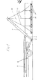
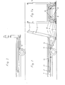
- the frame of the truck (1) and the loading area (2) can be seen in FIGS. 2, 2a and 3.
- the swivel arms (3) can be telescoped upwards (4) and have integrated support plungers (5) which can be extended downwards and rotated around on base plates (6) the pivot axis (7) are attached.
- the support rams (5) By extending the support rams (5) until the base plates (6) are lowered to the floor, the pivot point of the swivel arms (3) is moved close to the floor and the vertical forces acting on the loaded swivel arms (3) become direct without using the truck chassis derived into the ground.
- the swivel arms (3) are connected to each other by a telescopic crosshead (8) and a telescopic base plate connector (9). Both connections can be locked in their end positions (transport position: swivel arms (3) within the width profile of the vehicle and working position: swivel arms outside the loading area width).
- the base plates (6) are rotatably connected in two dimensions to handlebars (10) which are rotatably attached to the vehicle frame (2) in two dimensions. One axis of rotation is inclined upwards transversely to the longitudinal axis of the vehicle, and the second axis of rotation is rotated through 90 °. In the transport position (Fig.
- the handlebars (10) are approximately parallel to the vehicle frame (1).
- the swivel arms (3) are carried by the swivel cylinders (11) while the swivel arms (3) are extended in the working position (after releasing the locks).
- the base plates are moved downwards by extending the support punches (5).
- the handlebar sliding surfaces (13) are designed vertically, so that the floor plates (6) (after they have been swung out far enough) only perform a vertical movement when the support rams (5) are actuated.
- the crosshead (8) and base plate connector (9) are locked in their end positions.
- the swivel cylinders (11) are articulated on the one hand rotatably on the crosshead (8) and on the other hand rotatably on the vehicle frame (1).
- the actuating forces required for moving the load by swiveling the swivel arms (3) are transmitted from the swivel cylinders (11) through the crosshead (8) to the swivel arms (3).
- the drives of the swivel arms namely that especially when the swivel arms are at an incline, on the one hand the occurring load moments are greatest, but on the other hand the lever arm of the force attack becomes ever smaller, the lever arm of the force attack becomes the embodiment of this invention
- Swivel cylinder (11) by extending and retracting the support stamp (5) constantly approximately constant ge hold. The control pulse required for this is picked up by the support stamp control valves (14) between the swivel cylinder (11) and the vehicle frame (1).
- This control process works automatically, regardless of whether it is triggered by pressing the base plates (6) into soft ground, by moving the swivel arms (3) or by the vehicle suspension relaxing when the load is lifted from the loading area and an upward movement of the loading area ( 2) and vehicle frame (1).
- the fact that the two support punches (5) are controlled independently of one another also automatically compensates for a transverse inclination of the vehicle.
- the swivel arms (3) are firmly connected to rotary piston systems (15) and rotate about the axis of the swivel shaft (7).
- the hollow shafts of the rotary piston systems (15) there are pins (16) which cannot be rotated but can be displaced with an adjusting device (18).
- the pins (16) and the hollow shafts of the rotary piston systems (15) are non-positively connected, for example by spline profiles, so that the outer parts of the rotary pistons connected to the swivel arms (3) systems (15) can rotate around the axis of the swivel shaft (7) under power.
- the pivot shaft (7) is fixedly connected to the frame of the vehicle for the transmission of the torque acting on it.
- the swivel arms (3) are rotatably mounted in the hinge legs (17).
- the swivel arms (3) In order to bring the swivel arms (3) in the transport position under the loading surface (2) without exceeding the width profile, they are brought into a position horizontally ahead with the help of the rotary piston systems (15) (Fig. 5).
- the pins (16) are moved to the center of the vehicle with the adjusting device (18) and thereby pulled out of the hollow shafts of the rotary piston systems (15).
- the swivel arms (3) are folded inward about the axes (19) by the adjusting device (18) or with a special device.
- the swivel arms (3) can also be arranged displaceably on the swivel shaft (7) with the omission of the displaceable pins (16), so that they can be moved inwards in the transport position.
- the support legs (20) are connected to one another with an adjustable strut (21).
- the spreading angle of the support legs (20) can be varied by adjusting the strut (21).
- the support legs are provided with movable base plates (6).
- Both support legs (20) are rotatably connected at point (22) to the support bracket (23) which in turn is rotatably attached to the pivot pin (24) of the load arm (3).
- the pivot pins (24) seen when the swivel arm is above the loading area, are below the longitudinal axis of the swivel arm (3). attached. This ensures that the counterweight effect of the vehicle weight is the same even when the swivel arms (3) are inclined at different angles when picking up the load from the ground on the one hand and when depositing the load on the loading surface (2).
- the support legs (20) When lowering the swivel arm (3), the support legs (20) rest on the floor. With the help of the torque of the rotary piston system (15), the swivel shaft (7) is raised above the pivot pin (24). The support bracket (23), rotating around the point (22) fixed by the support legs, compensates for the horizontal movement of the pivot pin (24), so that the pivot shaft (7) and thus the vehicle does not change its position in the horizontal direction. (The lateral play of the carrying strap (23) can be limited by appropriately attached stops). If the swivel arms (3) are swiveled upwards when the load is picked up, the vehicle weight raised as described above acts as a counterweight.
- the lifting force to be applied is reduced in the area of its maximum value by the proportion of the vehicle weight and the hydraulic lifting device can be dimensioned correspondingly smaller.
- the proportional vehicle weight acts as a counterweight and in the same way reduces the deceleration forces to be applied by the hydraulic lifting device.
- the division of the loads between the support device and the articulation of the swivel arms (3) on the vehicle has an advantageous effect on the dimensioning of the components out.
- the fulcrum (22) of the support legs (20) can be provided in line with the axis of the swivel shaft (7) while foregoing advantages, or a support device can be dispensed with entirely.
- the loading device can be designed in such a way that the lifting and turning force is generated by a commercially available hydraulic swivel drive which is attached to the frame of the vehicle e.g. is fixed in the middle of the vehicle, with its drive shaft (7) it is part of the swivel shaft (7) rotatably mounted on the vehicle frame (2) and moves the swivel arms (3) via the displaceable pins (16).
- a commercially available hydraulic swivel drive which is attached to the frame of the vehicle e.g. is fixed in the middle of the vehicle, with its drive shaft (7) it is part of the swivel shaft (7) rotatably mounted on the vehicle frame (2) and moves the swivel arms (3) via the displaceable pins (16).
- the lifting and turning force for the swivel arms (3) can be provided by commercially available hydraulic cylinders, which are mounted inside or outside the vehicle frame (1) approximately horizontally and via the crankshaft (7) cranked for this purpose, the force on the crank drive Transfer the swivel shaft (7) rotatably mounted on the vehicle frame (1).
- these can be provided with hydraulically telescopic upper parts (4).
- the lifting gear can also include: foot hooks (34) Securing brackets (35), securing strands (36), turnbuckles (37), double hooks (38), load arms (39 Fig. 17) and guide forks when using lifting gear for trucks without tail lifts (40 Fig. 22) and when used for skip loaders loading flaps ( 41 Fig. 21).
- the lifting gear for a vehicle includes two sets of load-bearing strands (33) with stop members (32) and at least one, usually 2 pallet carriers (31) for 2 pallets standing next to each other later in the direction of travel.
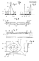
- the pallet carrier (31) (FIGS. 8 and 9) preferably has a round cross-section, other cross-sectional shapes (oval, square, rectangular, triangular or other) are conceivable.
- end plates (42) At the ends of the pallet carrier (31) there are end plates (42) with preferably approximately oval holes (43) for receiving the stop members (32).
- the pallet carrier (31) is introduced into the free spaces between the pallet feet near the outer feet in the flatter position.
- the pallet carrier (31) is moved to the lifting position by rotating it by approximately 90 °.
- the angled corners (44) of the end plates (42) capture the upper outer boundaries of the pallets, if necessary, press the pallets together and secure the pallets against displacement during the lifting process.
- the stop members (32) with the load-carrying strands (33) are attached and the load can be lifted.
- this force is provided at the beginning of the lifting process in that the approximately oval design of the holes (43) in the end plates (42) attacks the lifting force off-center and completes the rotation of the pallet carrier (31) in the lifting position (end plate approximately upright) .
- the inserted pallet carriers (31) are only attached to the accessible side.
- the angled corners (44) of the end plates (42) sit in the gap (45) between the pallets to be picked up (46) and the pallets remaining (47).
- the pallets to be picked slide in the direction of the arrow and the previously inaccessible holes (43) in the pallet carriers (31) for striking the remaining load-carrying strands (33) are exposed
- the pallet carrier (31) preferably consists of a middle piece (48) and two side pieces (49) which can be moved telescopically in the middle piece. It can thus be brought to the level required for the pallets to be recorded.
- the side pieces (49) (FIG. 9) can be locked by a spring (50) in the side pieces, on which two bolts are fastened.
- the locking bolt (51) protrudes through a hole in the side piece (49) into correspondingly selectable holes in the middle piece (48). Pressing the operating pin (52) in the side piece 49 releases the spring (50) moved down and the locking bolt (51) snaps out of the center piece (48). After releasing the operating pin (52), the spring force presses the locking pin (51) into the selected hole in the center piece (48).
- Other forms of locking are conceivable.
- the pallet carriers (31) can also be designed with only one telescopic side piece (49) or without adjustment.
- the side pieces (49) can be provided with reinforcements (53) which bring the cross section of the side pieces (49) to the dimensions of the middle piece (48) in the load-bearing area.
- these reinforcements can be appropriately prepared by using non-slip materials (rubber, plastics, nubbed or pointed metal parts, etc.).
- the side pieces (49) are closed by end plates (42 Fig. 10).
- the dimension (a) of the end plates (42) should preferably not exceed the corresponding cross-sectional dimension (b) of the center piece (48) in order to facilitate the insertion of the pallet carrier (31).
- the dimension (c) of the end plates (42) should preferably be larger than the vertical space formed by the tallet feet (according to the standard 100 mm) in order to ensure correct positioning of the pallet carrier (31) in the lifting position before, during and after the lifting process.
- the corner (44) of the end plate (42) is preferably angled outwards and sharpened or rounded at the edge (45). This ensures that the pallets to be picked up by the pallet carrier (31) are also captured according to the invention if they are flush with other pallets or the two pallets of a pair are not flush.
- the tab (56) of the end plate (42) is preferably bevelled at its edge (57) so that when the pallet carrier is rotated in the lifting position it comes into contact with the lower connecting board of the pallet feet only after the outer corner (44) has the upper one Limitation of the pallet has already covered.
- the edge (57) of the tab (56) is preferably round in its central part in order to counter the rotation of the pallet carrier in the lifting position with as little resistance as possible. Angling the tab (56) according to the angle of the corner (44) can be useful.
- FIG. 11 Another form of the pallet carrier (31) is shown in FIG. 11.
- a suspension pin (59) is attached to the end plate (42) for attaching the load-bearing strands (33), preferably off-center to the longitudinal axis of the pallet carrier (31) in the direction of the greatest extent of the end plate (42), on the one hand at the beginning of the Lifting process to rotate the pallet carrier (31) with leverage and thereby generate sufficient force to trigger a gapless movement of the pallets and, on the other hand, to keep the pallet carrier (31) in stable equilibrium under load.
- the dimension (f) must not exceed the dimension (g) in order to leave space for the hanging pin (59) in the openings of the neighboring pallet that can no longer be accommodated when the pallets are standing together.
- a central attachment of the suspension pins (59) is also conceivable.
- the hanging pin (59) consists of a cylindrical part with an end plate of approximately oval contour.
- the narrower dimension of the end plate is also larger than the cylindrical part and points in the direction of the greatest extent of the end plate (42) in order to ensure secure locking with the load arm (39) in the lifting position.
- Other contours of the cover plate are conceivable.
- end plates of the suspension pins (59) can be provided with holes (43) so that the pallet carriers can be used both with load arms (39) and with stop members (32).
- the suspension pins (59) can also be inserted into the end plates (42) and designed to be lockable in both end positions in order to be able to adapt the total length of the pallet carriers (31) to the available space on the loading surface of transport vehicles for transport.
- the load-carrying strands (33) are combined differently depending on the number of pallets to be lifted at the same time.
- One design is shown in FIG. 12 for 3 pairs of pallets and in FIG. 13 for 5 pairs of pallets. Other design forms are conceivable.
- the load-bearing strands (33) branch downward and, as shown in FIG. 12, are each connected to two pallet carriers (31 and 31 a) of different pairs of pallets (60 and 61), so that the two pairs of pallets are pressed together under load.
- the outer load-bearing strands (33) are usually equipped with foot hooks (34).
- a cable segment-shaped cable holder (93 Fig. 14) can be used according to the invention at the branching points. It has an eye in its upper part, which can also have the shape of a padlock.
- Distributed over the reinforced lower part of the cable holder (93) are frustoconical, tapering pockets (94), which are slit open on the sides so that a the corresponding rope can be inserted according to the load capacity.
- the upper openings of the pockets (94) can be closed by a rotatable securing plate (95). It can be secured.
- the rope (96) used as a load-bearing strand carries conical compression rope clamps at both ends, the conical shape of which corresponds to the shape of the pockets (94).
- the rope can carry several press rope clamps (97) one above the other, so that the rope length can be adapted to different needs.
- the stop members (32) are band-shaped and fork-shaped in their upper part and have a round pin (62) at their lower end, on which in turn an end plate (63) is firmly attached.
- the upper edge of the end plate is rounded with the radius (d), which corresponds to the radius of the larger arc of the hole (43) in the end plate (42) of the pallet carrier (31).
- the dimension (h) is slightly less than the distance of the smaller arc in the hole (43) of the end plate (42) from the inside diameter of the pallet carrier (31).
- the dimension (i) of the end plate (63) corresponds to the largest opening width of the hole (43) and measure (k) is larger than measure (i).
- the length of the spigot should be kept as short as possible.
- this design of the pin (62), end plate (63) and hole (43) of the end plate 42 of the pallet carrier (31) ensures that the stop member (32) is only in a certain position relative to the hole (43). with the lower part can first be inserted at an angle and connected to the pallet carrier by moving it into a position perpendicular to the longitudinal axis of the pallet carrier in such a way that it cannot detach itself either under load or without load.
- a removable and lockable bolt (65) for receiving the foot hook (34).
- This bolt (65) has an inclined surface (66) which corresponds to the inclination of the edges (70) of the foot hook (34).
- a further, similarly shaped pin (67) for receiving in guide forks (40) can be attached opposite the lower pin (62).
- the foot hooks (34) Fig. 16 have on their long legs an elongated hole (68) with upward-looking, tooth-like extensions (69) whose opening width corresponds to the diameter of the bolt (65).
- the bevelling of the edges (70) is different and is designed so that the foot hook (34) in the load-bearing position of the stop member (32) points with its upper edge to the upper end of the pallet foot on the outside. This ensures that even with different dimensions of the pallet feet, the foot hook (34) always acts on the upper part of the foot.
- the shorter leg of the foot hook (34) is angled twice and thus encompasses the pallet foot.
- This has an eye (71) at the top for fastening the load-bearing strand (33) and at the bottom an opening (72) with a contour that corresponds to that of the end plate of the suspension pin (59) and with the largest opening width in the direction of the longitudinal axis of the load arm (39 ) lies.
- the load arm (39) can only be slid over the suspension pin (59) in a certain position, while in all other positions, in particular under load, there is a connection between the parts which cannot be released automatically.
- foot hooks (34) are additionally attached on the side facing the pallet carrier so as to be rotatable about the opening (72).
- the attachment of the foot hook (34) between the load arm (39) and the pallet carrier (31) ensures that the foot hook (39) is held in a position parallel to the end plate (42) and thus to the pallet carrier under load.
- the foot hooks then have a hole (73) larger than the end plate of the suspension pin (59), so that the load arm (39) and foot hook (34) can be slipped on in different positions of the load arm (39) with an approximately horizontal foot hook (34).
- the other leg of the foot hook (34) is bent twice at right angles and encompasses the outer pallet foot. As a result, the outermost pallet carrier (31) of the Hieve is held in the immediate vicinity of the outer pallet feet even under load.
- the pallet load (FIG. 8) can be carried out by securing brackets (35) and securing strands (36) during be secured during transport.
- the securing strands (36) are connected to a branching point of the load-carrying strands (33) and form a non-positive connection to a pallet carrier of an inner pair of pallets via this with a lower load-carrying strand.
- the necessary pretension can be brought about by means of turnbuckles (37) in the safety lines (36).
- the securing brackets (35) generally consist of two parts which can be telescoped and locked in different lengths, so that their length can be adapted to the dimensions of the load. They can also be made non-adjustable.
- the load-carrying strands (33) and the securing strands (36) can be designed entirely or partially in the form of chains, polyester belts, band-shaped metal or plastic parts or ropes with the associated connecting links.
- the upper suspension heads (74) of the lifting gear must be connected to the crane hook using a conventional crossbar. If, for example, goods palletized in a port are unloaded with a crane using the lifting tackle according to the invention and then immediately conveyed to the end, for example with skip loaders, the lifting tackle can be used instead of the upper suspension heads or subsequently Double hook (38) Fig. 18 can be equipped.
- the load-bearing strands or the suspension heads are then attached in the eye (75), which can be designed as a U-lock, commercially.
- the crane When unloading, the crane heaves the heave up to just above the loading area of the skip loader between the swivel arms. Now the swivel arms are swung into the lower side openings of the double hook. By lowering the traverse, the support bolts of the swivel arms (3) slide up to the round end of the recesses (76) and transfer the load. If the crossbar is lowered further, the eyes of the crossbar slide out of the upper recess (76). The hieve is taken over by the demountable tipper and can be placed on its loading surface for further transport.
- two pallet carriers (31) are positioned under the wheels of each axle and a load-bearing strand (33) for the pallet carriers (31) of one axle is split in each case.
- the load-carrying strands (33) can be equipped with shortening members.
- the lifting gear can be designed in the form of loading platform side walls. 19 shows three pairs of pallets (60) standing next to each other, connected to one another by pallet carriers (31). A drop side is shown above.
- the tailgate upper part (79) is load-bearing and is connected to the loading device via eyes and load-bearing strands.
- Loops (80) made primarily from wire rope are used as the connection between the top wall part (79) and pallet carriers (31) (FIG. 20), into which a full thimble is integrated at the top and bottom.
- the lower thimble carries pins (62) with an end plate (63) as described for the stop member (32).
- the upper thimble has a continuous bolt that protrudes on both sides.
- the top wall part (79) is provided with slits which are open at the bottom and correspond to the thickness of the upper thimbles.
- the bolts protruding from the upper thimble are carried by the reinforced lower edges of the top wall part (79).
- the slots are distributed in such a way that all desired pallet dimensions can be attached with vertically hanging rope loops.
- the vertical end boundaries (81) Fig. 20 of the top wall part (79) are reinforced and open at the bottom.
- the drop side lower part (83) is connected to the drop side upper part (79) so as to be rotatable about a horizontal axis. It can be folded upwards by 180 ° and locked with the upper part of the drop side (79).
- the free-hanging side wall lower parts (83) are angled outward by approximately 5 ° by spring force or in another suitable manner.
- beads for receiving the rope loops can be incorporated, which prevent movement of the loops (80) together with the associated pallet carriers (31) in the direction of the longitudinal axis of the vehicle and thus fulfill a transport securing function during transport.
- the vertical end boundaries (84) of the lower part of the drop side (83) are U-shaped in the upper part with parallel legs open to the loading area, while the distance between the legs widens downwards.
- the tips of the stanchions (82) first come into contact with the end boundaries (84) of the lower side parts (83) which are slightly spread outwards.
- the lower side parts of the drop side slide with their end limits (84) from the stanchions into the correct position.
- the upper ends of the stanchions (82) penetrate into the lower end openings (81) of the upper side of the drop side divide (79). They press against the upper edge of the end limits (84) of the lower part of the drop side (84) and push them against the spreading spring force in a vertical position.
- the drop side lower parts (83) are connected to the loading surface (2) at the bottom via releasable hinges (85). As a result, after the stanchions (82) have been pulled out downwards, the side walls can be folded down like normal side walls.
- the top and bottom parts of the side wall are connected to the front and rear walls in the usual way.
- FIG. 21 For pallet transport with skip loaders, these (Fig. 21) are equipped with two loading flaps (41) closing the loading area to the rear. They serve for the precise positioning during the depositing of the load on the loading area, the expansion of the loading area to a pallet-compatible size and the securing of the load during transport.
- the loading flaps (41) have a 1-shaped cross section and are closed off by end plates on the sides facing away from the center of the vehicle. They are rotatably mounted on the main shaft (86) connecting the swivel arms of the skip loader.
- the bearing blocks (87) of the sliding bolt (88) are fastened to the loading flaps (41) in such a way that a non-positive connection to the catch hook (83) is produced with the sliding bolt (88).
- Turnbuckles are attached to the end plates at the connection points (91), which flap the hatch (41) horizontally Connect the load bearing position to the loading area.
- the loading flaps hang down.
- the loading flaps (41) are connected to the catch hook (89) by means of the sliding lock (88). As soon as the load hovers over the loading area immediately before lowering, the catch hook (89) is actuated. The loading flaps (41) guide the still suspended load into the correct position.
- guide forks (40) can be attached to the loading surface (2).
- the guide forks (40 are used to guide the load into the correct position shortly before being placed on the loading surface, namely transversely to the direction of travel through the surfaces of the guide forks and in the direction of travel by receiving the suspension pins (59) or the pins (67) of the stop member (32) into the opening of the fork, and after the load has been set down, they serve to protect the Trarsports by giving the hanging pins (59) and thus the pallet carriers (31) a position which cannot be changed in any direction.
- the guide forks (40) have an upward opening which is considerably larger than the diameter of the cylindrical part of the suspension pins (59), tapers downwards and ends in an area with parallel boundaries. in this area the opening width (92) is slightly larger than that Diameter of the cylindrical part of the pin (59), but smaller than the end plate.
- the guide fork (40) is mounted so that it can be rotated outward about 10 ° about a horizontal axis from the vertical. as a result, the load is easily grasped when the load is lowered, and the guide fork (40) is placed in the vertical position after the load has been lowered through the end plates of the suspension pins (59).
- the guide forks can be equipped with horizontally attached slide locks that can be locked in the "open” and "CLOSED” positions and which close off the lower part of the fork opening.
- the fork opening is closed to secure it in transit, thus locking the hanging pin (59) and thus the pallet carrier (31) and the load upwards.
- the guide forks (40) are folded about their horizontal axis from its position about 10 ° off-normal to about 100 0 inwardly in the horizontal. Its axis of rotation is mounted in a trough-shaped fitting which is let into the loading area (2) and has a contour which corresponds to that of the guide fork (40) and has a depth corresponding to its thickness. As a result, the guide fork (40) can be folded flush into the loading area (2) if necessary.
- the guide forks can also be designed to be foldable under the loading area.
Landscapes
- Engineering & Computer Science (AREA)
- Mechanical Engineering (AREA)
- Transportation (AREA)
- Forklifts And Lifting Vehicles (AREA)
- Loading Or Unloading Of Vehicles (AREA)
- Vehicle Cleaning, Maintenance, Repair, Refitting, And Outriggers (AREA)
- Jib Cranes (AREA)
Priority Applications (1)
| Application Number | Priority Date | Filing Date | Title |
|---|---|---|---|
| AT86113952T ATE83713T1 (de) | 1985-10-11 | 1986-10-08 | Ladeeinrichtung, insbesondere fuer lastkraftwagen, mit zwei vornehmlich hydraulisch betaetigten schwenkarmen. |
Applications Claiming Priority (4)
| Application Number | Priority Date | Filing Date | Title |
|---|---|---|---|
| DE19858528955 DE8528955U1 (de) | 1985-10-11 | 1985-10-11 | Hebegeschirr für Paletten und ähnliche Lasten |
| DE8528956U | 1985-10-11 | ||
| DE8528955U | 1985-10-11 | ||
| DE19858528956 DE8528956U1 (de) | 1985-10-11 | 1985-10-11 | Ladeeinrichtung, insbesondere für Lastkraftwagen, mit zwei vornehmlich hydraulisch betätigten Schwenkarmen |
Publications (3)
| Publication Number | Publication Date |
|---|---|
| EP0220560A2 true EP0220560A2 (fr) | 1987-05-06 |
| EP0220560A3 EP0220560A3 (en) | 1989-07-26 |
| EP0220560B1 EP0220560B1 (fr) | 1992-12-23 |
Family
ID=25950466
Family Applications (1)
| Application Number | Title | Priority Date | Filing Date |
|---|---|---|---|
| EP86113952A Expired - Lifetime EP0220560B1 (fr) | 1985-10-11 | 1986-10-08 | Dispositif de chargement, en particulier pour véhicules, comprenant deux bras basculants actionnés particulièrement hydrauliquement |
Country Status (3)
| Country | Link |
|---|---|
| EP (1) | EP0220560B1 (fr) |
| AT (1) | ATE83713T1 (fr) |
| DE (1) | DE3687340D1 (fr) |
Cited By (11)
| Publication number | Priority date | Publication date | Assignee | Title |
|---|---|---|---|---|
| FR2627440A1 (fr) * | 1988-02-24 | 1989-08-25 | Bennes Marrel | Vehicule de transport a bras de chargement lateralement mobiles |
| AU639831B2 (en) * | 1990-10-01 | 1993-08-05 | Robin Enard Wynyard | A load transferring device |
| WO1995021075A1 (fr) * | 1994-02-04 | 1995-08-10 | Ove Hammarstrand | Dispositif de levage |
| CN108382285A (zh) * | 2018-04-13 | 2018-08-10 | 江苏高德液压机械有限公司 | 随车抓防脱装置 |
| CN108407698A (zh) * | 2018-04-13 | 2018-08-17 | 江苏高德液压机械有限公司 | 随车抓抓具 |
| CN109534020A (zh) * | 2018-12-20 | 2019-03-29 | 苏奕鹄 | 一种货物的自动搬运方法 |
| CN114619938A (zh) * | 2020-12-09 | 2022-06-14 | 海沃控股有限公司 | 拉臂车及其操作方法 |
| AU2017283005B2 (en) * | 2016-06-22 | 2022-10-20 | Crh Concrete A/S | A lifting system and a carrier element for such a lifting system |
| CN117303208A (zh) * | 2023-11-30 | 2023-12-29 | 山东中杰特种装备股份有限公司 | 一种压力容器翻转装置 |
| CN118929404A (zh) * | 2024-08-26 | 2024-11-12 | 江苏广瀛物流控股有限公司 | 一种物流运输大件卸货结构及其方法 |
| CN120157035A (zh) * | 2025-05-20 | 2025-06-17 | 河南省全安重工起重机有限公司 | 一种建筑材料运输用起重装置 |
Family Cites Families (7)
| Publication number | Priority date | Publication date | Assignee | Title |
|---|---|---|---|---|
| US2099116A (en) * | 1936-05-07 | 1937-11-16 | Western Electric Co | Clamp |
| CH339720A (de) * | 1955-12-16 | 1959-07-15 | Von Roll Ag | Kranlasttraverse zum Transport von palettiertem Gut |
| GB1255630A (en) * | 1968-11-19 | 1971-12-01 | I And P Lifting Gear Ltd | Improvements in lifting devices |
| FR2154382B1 (fr) * | 1971-09-30 | 1974-09-27 | Manutentio Socoma Coop | |
| DE2322657C2 (de) * | 1973-05-05 | 1982-02-11 | Bernhard Dipl.-Ing. 1000 Berlin Leuschner | "Fahrzeug, insbesondere Lkw, mit einem dem Transport von Stahlbetonraumzellen, insbesondere Fertiggaragen, dienenden Aufbau" |
| DE2421074A1 (de) * | 1974-05-02 | 1975-11-20 | Ulrich Padberg | Palettengeschirr zum verladebetrieb mit kraenen |
| AT341348B (de) * | 1976-03-29 | 1978-02-10 | Goldhofer Fahrzeugwerk | Mehrachsiges fahrzeug mit einer ladeplattform |
-
1986
- 1986-10-08 DE DE8686113952T patent/DE3687340D1/de not_active Expired - Fee Related
- 1986-10-08 AT AT86113952T patent/ATE83713T1/de not_active IP Right Cessation
- 1986-10-08 EP EP86113952A patent/EP0220560B1/fr not_active Expired - Lifetime
Cited By (13)
| Publication number | Priority date | Publication date | Assignee | Title |
|---|---|---|---|---|
| EP0330574A1 (fr) * | 1988-02-24 | 1989-08-30 | Marrel | Véhicule de transport à bras de chargement latéralement mobiles |
| FR2627440A1 (fr) * | 1988-02-24 | 1989-08-25 | Bennes Marrel | Vehicule de transport a bras de chargement lateralement mobiles |
| AU639831B2 (en) * | 1990-10-01 | 1993-08-05 | Robin Enard Wynyard | A load transferring device |
| WO1995021075A1 (fr) * | 1994-02-04 | 1995-08-10 | Ove Hammarstrand | Dispositif de levage |
| AU2017283005B2 (en) * | 2016-06-22 | 2022-10-20 | Crh Concrete A/S | A lifting system and a carrier element for such a lifting system |
| CN108382285A (zh) * | 2018-04-13 | 2018-08-10 | 江苏高德液压机械有限公司 | 随车抓防脱装置 |
| CN108407698A (zh) * | 2018-04-13 | 2018-08-17 | 江苏高德液压机械有限公司 | 随车抓抓具 |
| CN109534020A (zh) * | 2018-12-20 | 2019-03-29 | 苏奕鹄 | 一种货物的自动搬运方法 |
| CN114619938A (zh) * | 2020-12-09 | 2022-06-14 | 海沃控股有限公司 | 拉臂车及其操作方法 |
| CN117303208A (zh) * | 2023-11-30 | 2023-12-29 | 山东中杰特种装备股份有限公司 | 一种压力容器翻转装置 |
| CN117303208B (zh) * | 2023-11-30 | 2024-02-02 | 山东中杰特种装备股份有限公司 | 一种压力容器翻转装置 |
| CN118929404A (zh) * | 2024-08-26 | 2024-11-12 | 江苏广瀛物流控股有限公司 | 一种物流运输大件卸货结构及其方法 |
| CN120157035A (zh) * | 2025-05-20 | 2025-06-17 | 河南省全安重工起重机有限公司 | 一种建筑材料运输用起重装置 |
Also Published As
| Publication number | Publication date |
|---|---|
| EP0220560B1 (fr) | 1992-12-23 |
| ATE83713T1 (de) | 1993-01-15 |
| DE3687340D1 (de) | 1993-02-04 |
| EP0220560A3 (en) | 1989-07-26 |
Similar Documents
| Publication | Publication Date | Title |
|---|---|---|
| DE68902720T2 (de) | Hebe- und transportvorrichtung. | |
| AT506371B1 (de) | Entladefahrzeug und kombination eines entladefahrzeuges mit einer behälterabdeckung | |
| DE60003193T2 (de) | Frachtcontainer | |
| EP2423147B1 (fr) | Agencement destiné à retourner une charge | |
| DE2242001C3 (de) | Lasttragvorrichtung zum Anbau an einen Kranausleger | |
| EP0220560B1 (fr) | Dispositif de chargement, en particulier pour véhicules, comprenant deux bras basculants actionnés particulièrement hydrauliquement | |
| EP0949161B1 (fr) | Procédé et dispositif pour un système de manipulation de fret | |
| DE1803451A1 (de) | Hubgestell fuer Frachtbehaelter | |
| DE1680107C3 (de) | Vorrichtung für Fahrzeuge zum Auf- und Abladen von Lasten | |
| DE4328635C1 (de) | Ladegeschirr mit beweglichen Kupplungsorganen, insbesondere verdrehbaren Verriegelungsbolzen | |
| EP0251219A2 (fr) | Véhicule de transport muni d'un dispositif de chargement pour conteneur, cellule ou récipient | |
| EP0328878A2 (fr) | Véhicule utilitaire pour le transport de conteneurs | |
| DE2647227C2 (de) | Umschlaggerät zum Heben und Kippen von Frachtcontainern für Schüttgut | |
| DE1267167B (de) | Vorrichtung zur Handhabung von Stueckguetern | |
| EP0438998B1 (fr) | Voiture de transport, en particulier voiture à bas niveau, ainsi que méthode pour le chargement et le déchargement de ladite voiture | |
| EP1694586B1 (fr) | Palonnier | |
| DE3007279A1 (de) | Seitenlader fuer behaelter | |
| EP1688300B1 (fr) | Dispositif pour charger et décharger une plate-forme | |
| DE102006014731A1 (de) | Hubfahrzeug mit Kippcontainer | |
| DE8528955U1 (de) | Hebegeschirr für Paletten und ähnliche Lasten | |
| DE3336668A1 (de) | Kippaufbau an kraftfahrzeugen, insbesondere fuer mulden-hinterkipper | |
| DE3338538C2 (de) | Bewegbarer Lastenträger in Form eines Fahrzeuganhängers | |
| DE69734127T2 (de) | Mehrzweck-Container | |
| DE3407568A1 (de) | Wechselbehaelter-transport-system | |
| EP1364829A2 (fr) | Véhicule pour conteneurs |
Legal Events
| Date | Code | Title | Description |
|---|---|---|---|
| PUAI | Public reference made under article 153(3) epc to a published international application that has entered the european phase |
Free format text: ORIGINAL CODE: 0009012 |
|
| AK | Designated contracting states |
Kind code of ref document: A2 Designated state(s): AT BE CH DE FR GB IT LI LU NL SE |
|
| RTI1 | Title (correction) | ||
| RHK1 | Main classification (correction) |
Ipc: B60P 1/48 |
|
| PUAL | Search report despatched |
Free format text: ORIGINAL CODE: 0009013 |
|
| AK | Designated contracting states |
Kind code of ref document: A3 Designated state(s): AT BE CH DE FR GB IT LI LU NL SE |
|
| 17P | Request for examination filed |
Effective date: 19900125 |
|
| 17Q | First examination report despatched |
Effective date: 19910306 |
|
| GRAA | (expected) grant |
Free format text: ORIGINAL CODE: 0009210 |
|
| AK | Designated contracting states |
Kind code of ref document: B1 Designated state(s): AT BE CH DE FR GB IT LI LU NL SE |
|
| PG25 | Lapsed in a contracting state [announced via postgrant information from national office to epo] |
Ref country code: SE Effective date: 19921223 Ref country code: NL Effective date: 19921223 |
|
| REF | Corresponds to: |
Ref document number: 83713 Country of ref document: AT Date of ref document: 19930115 Kind code of ref document: T |
|
| REF | Corresponds to: |
Ref document number: 3687340 Country of ref document: DE Date of ref document: 19930204 |
|
| ITF | It: translation for a ep patent filed | ||
| ET | Fr: translation filed | ||
| NLV1 | Nl: lapsed or annulled due to failure to fulfill the requirements of art. 29p and 29m of the patents act | ||
| GBT | Gb: translation of ep patent filed (gb section 77(6)(a)/1977) |
Effective date: 19930421 |
|
| PLBE | No opposition filed within time limit |
Free format text: ORIGINAL CODE: 0009261 |
|
| STAA | Information on the status of an ep patent application or granted ep patent |
Free format text: STATUS: NO OPPOSITION FILED WITHIN TIME LIMIT |
|
| PG25 | Lapsed in a contracting state [announced via postgrant information from national office to epo] |
Ref country code: LU Free format text: LAPSE BECAUSE OF NON-PAYMENT OF DUE FEES Effective date: 19931031 |
|
| 26N | No opposition filed | ||
| PGFP | Annual fee paid to national office [announced via postgrant information from national office to epo] |
Ref country code: CH Payment date: 19951013 Year of fee payment: 10 |
|
| PGFP | Annual fee paid to national office [announced via postgrant information from national office to epo] |
Ref country code: AT Payment date: 19961014 Year of fee payment: 11 |
|
| PGFP | Annual fee paid to national office [announced via postgrant information from national office to epo] |
Ref country code: FR Payment date: 19961028 Year of fee payment: 11 |
|
| PG25 | Lapsed in a contracting state [announced via postgrant information from national office to epo] |
Ref country code: LI Effective date: 19961031 Ref country code: CH Effective date: 19961031 |
|
| PGFP | Annual fee paid to national office [announced via postgrant information from national office to epo] |
Ref country code: BE Payment date: 19961205 Year of fee payment: 11 |
|
| PGFP | Annual fee paid to national office [announced via postgrant information from national office to epo] |
Ref country code: DE Payment date: 19961212 Year of fee payment: 11 |
|
| REG | Reference to a national code |
Ref country code: CH Ref legal event code: PL |
|
| PG25 | Lapsed in a contracting state [announced via postgrant information from national office to epo] |
Ref country code: AT Free format text: LAPSE BECAUSE OF NON-PAYMENT OF DUE FEES Effective date: 19971008 |
|
| PGFP | Annual fee paid to national office [announced via postgrant information from national office to epo] |
Ref country code: GB Payment date: 19971010 Year of fee payment: 12 |
|
| PG25 | Lapsed in a contracting state [announced via postgrant information from national office to epo] |
Ref country code: FR Free format text: THE PATENT HAS BEEN ANNULLED BY A DECISION OF A NATIONAL AUTHORITY Effective date: 19971031 Ref country code: BE Free format text: LAPSE BECAUSE OF NON-PAYMENT OF DUE FEES Effective date: 19971031 |
|
| BERE | Be: lapsed |
Owner name: WILCKE HANS Effective date: 19971031 |
|
| PG25 | Lapsed in a contracting state [announced via postgrant information from national office to epo] |
Ref country code: DE Free format text: LAPSE BECAUSE OF NON-PAYMENT OF DUE FEES Effective date: 19980701 |
|
| REG | Reference to a national code |
Ref country code: FR Ref legal event code: ST |
|
| PG25 | Lapsed in a contracting state [announced via postgrant information from national office to epo] |
Ref country code: GB Free format text: LAPSE BECAUSE OF NON-PAYMENT OF DUE FEES Effective date: 19981008 |
|
| GBPC | Gb: european patent ceased through non-payment of renewal fee |
Effective date: 19981008 |
|
| PG25 | Lapsed in a contracting state [announced via postgrant information from national office to epo] |
Ref country code: IT Free format text: LAPSE BECAUSE OF NON-PAYMENT OF DUE FEES Effective date: 20051008 |
|
| REG | Reference to a national code |
Ref country code: DE Ref legal event code: R081 Ref document number: 3687340 Country of ref document: DE Owner name: WILCKE, HANS, DE Free format text: FORMER OWNER: WILCKE, HANS, 53498 BAD BREISIG, DE |