EP0220575A2 - Mixing and kneading device - Google Patents
Mixing and kneading device Download PDFInfo
- Publication number
- EP0220575A2 EP0220575A2 EP86114051A EP86114051A EP0220575A2 EP 0220575 A2 EP0220575 A2 EP 0220575A2 EP 86114051 A EP86114051 A EP 86114051A EP 86114051 A EP86114051 A EP 86114051A EP 0220575 A2 EP0220575 A2 EP 0220575A2
- Authority
- EP
- European Patent Office
- Prior art keywords
- mixing
- housing
- kneading device
- mixer
- kneader shaft
- Prior art date
- Legal status (The legal status is an assumption and is not a legal conclusion. Google has not performed a legal analysis and makes no representation as to the accuracy of the status listed.)
- Granted
Links
Images


Classifications
-
- B—PERFORMING OPERATIONS; TRANSPORTING
- B01—PHYSICAL OR CHEMICAL PROCESSES OR APPARATUS IN GENERAL
- B01F—MIXING, e.g. DISSOLVING, EMULSIFYING OR DISPERSING
- B01F27/00—Mixers with rotary stirring devices in fixed receptacles; Kneaders
- B01F27/60—Mixers with rotary stirring devices in fixed receptacles; Kneaders with stirrers rotating about a horizontal or inclined axis
- B01F27/70—Mixers with rotary stirring devices in fixed receptacles; Kneaders with stirrers rotating about a horizontal or inclined axis with paddles, blades or arms
- B01F27/707—Mixers with rotary stirring devices in fixed receptacles; Kneaders with stirrers rotating about a horizontal or inclined axis with paddles, blades or arms the paddles co-operating, e.g. intermeshing, with elements on the receptacle wall
Definitions
- the invention relates to a mixing and kneading device according to the preamble of the claim.
- a mixing and kneading device of this type is known from DE-PS 23 49 106, in which a toroidal annular space, delimited by these and the housing and the shaft, is formed between each two adjacent disks and has hook-shaped, housing-fixed kneading only in its edge regions - And scraping elements is detected.
- a toroidal annular space delimited by these and the housing and the shaft, is formed between each two adjacent disks and has hook-shaped, housing-fixed kneading only in its edge regions - And scraping elements is detected.
- thorough mixing of the product is not guaranteed inside this toroidal space, which can lead to insufficient product homogeneity.
- a further disadvantage can result from the fact that product residues remain in the interior of the torus space that cannot be discharged, as a result of which the newly added product to be treated in the reactor can be damaged. When changing batches, undesirable product mixing between fresh and finished product can occur.
- the invention is therefore based on the object of achieving thorough mixing of the various product components in the entire product or reaction space, with a uniform dwell time of all product particles located in the reaction space being achieved.
- the conveying components can be changed as desired, for example, a greater slope can be provided in areas of the kneader shaft in order to ensure sufficient conveying components in radial and axial direction.
- the deflecting surfaces of the cross-sectional profiles of two mirror arms arranged diagonally offset in mirror image are designed such that both deflecting surfaces result in deflection components of the product flow in the same axial direction and in the opposite radial direction .
- additional mixing arms fastened to the kneader shaft protrude into the radially inner product space and provide additional shifting and mixing in this area.
- the additional mixing arm has the diagonal mixer arms in parallel in a shear gap associated shear edges, through which the product experiences intensive shearing and crushing.
- the additional mixer arm can only carry one shear edge or two shear edges which are alternately guided past the mixer arms which are diagonally offset in mirror image.
- an L-shaped scraper is arranged on the mixer arm fixed to the housing, from which one leg scrapes the disc element and the other leg scrapes the kneader shaft.
- stirrers are arranged at the ends of the scraper bars, which at the same time also contribute to the mixing of the radially outer product space.
- the stirrers with the vertical part of the mixer arm also intensively stir the amount of product in this area.
- FIG. 1 shows a mixing and kneading device with a kneader shaft 2 arranged coaxially in a cylindrical housing 1, each of which is mounted in an end wall 3 and 4 that closes the housing.
- the kneader shaft 2 passes through the end wall 4 and is coupled to a drive unit 5.
- the cylindrical housing 1 is shown broken away in a central partial region, in which the kneader shaft 2 and further functional elements can be seen, which can be seen more clearly from the figures 2 to 4 explained below.
- the housing 1 shows the housing 1 with a kneader shaft 2 mounted therein, on which disc elements 8 are arranged in planes lying perpendicular to the axis of the housing or kneader shaft, which extend to the inner wall of the housing including a gap.
- the disk elements 8 have an area corresponding to a sector of 60 °, wherein in each case three disk elements 8 are arranged offset by 120 °.
- these carry transverse scraper bars 10, which enclose a scraping gap with the housing inner wall and can be arranged at an angle to an axial surface line of the housing.
- the scraper bars 10 have stirrers 11 directed radially inwards at their ends.
- a mixer arm 12 is fastened in the middle of the housing wall between two levels of disk elements 8, which is directed radially inward in a first section 12a and then bends at an angle of 45 ° to the disk element 8 on the left in FIG. 2.
- Another mixer arm 12 'shown in broken lines in FIG. 2 is bent toward the right-hand disk element 8 and represents the mixer arm following in the circumferential direction, which is pivoted into the image plane of FIG. 2 for the purpose of illustration.
- two mixer arms with alternating bending direction are arranged, offset in the circumferential direction by 180 ° in each case.
- the mixer arms 12, 12 'carry L-shaped scrapers 13, 13' At their ends, the mixer arms 12, 12 'carry L-shaped scrapers 13, 13', one leg of which is assigned to the surface of the disk elements 8 and the other leg to the surface of the kneader shaft 2.
- the angled mixer arms 12, 12 ' divide the torus space enclosed by the inner surface of the housing 1, the kneader shaft 2 and the axially adjacent disc elements 8 into a radially outer product space P 1, P 1' and a radially inner product space P 2, P 2 '.
- Attached to the kneader shaft 2 in the plane between two axially adjacent disc elements 8 are a plurality, preferably two, of mixer arms 14 provided as additional mixer arms, which have the mixer arms 12, 12 'projecting diagonally into the toroidal space and having shear edges 15, 15' assigned in parallel at a shear gap .
- FIG. 4 shows the cross-sectional areas of a mixer arm 12 and a shear edge 15, against which a product stream flowing in the circumferential direction flows, which is divided by a cutting edge 16 arranged on the mixer arm 12 and deflected in a subsequent deflection surface 17.
- the product stream flowing past on the other side of the cutting edge is detected by the shear edge 15 and subjected to an intensive squeezing and shearing action as it moves past (arrow 18) the static mixer arm 12.
- a deflection can additionally be achieved by forming a deflecting surface 15a.
- the flow effects caused by the mixer arm 12, 12 'can thus be influenced in any way.
- the cutting edge 16 runs in a straight line on the mixer arm 12 shown in solid lines in FIG. 2, the deflection surface 17 being in the radially outer region, as a result of which the product stream impinging on this mixer arm 12 is deflected with a radially outwardly directed conveying component R 1 and with an axially to the left directional conveying component A1 experiences.
- the cutting edge 16' runs in a twisted shape, the deflecting surface 17 'lying in the radially inner region, as a result of which the product stream impinging on this mixer arm 12' deflects with a radially inwardly directed conveying component R2 and with the axially left-facing conveying component A2.
- the cutting edge 16 ' can also be twisted with the deflecting surface 17' in such a way that the product stream impinging on the mixing arm is deflected radially outwards and axially to the right with one part and radially inwards and axially to the left with the other part. Due to the fact that such a mixer arm divides the product stream into partial streams with oppositely directed axial conveying components, there is no uniform axial conveying component defined in an axial discharge direction, so that a mixing arm with an S-shape twisted cutting edge and deflection surface is mainly used for the purpose of intensive mixing. It is advantageous if mixer arms with differently directed deflection surfaces follow one another in the circumferential direction.
- FIG. 5 shows in full lines a further embodiment of a mixer arm 22 fastened to the housing 1, which projects radially inward between two adjacent disk elements 8 up to the kneader shaft 2 and there into an L shaped scraper 23, of which one leg is assigned to the disk element 8 and the other leg to the surface of the kneader shaft 2.
- the mixer arm 22 'shown in broken lines in FIG. 5 with the L-shaped scraper 23' corresponds in mirror image to the mixer arm 22 and its scraper 23 shown in solid lines and is arranged offset by 180 ° to the image plane of FIG. 5 in the housing.
- the deflection surface can be twisted over the radial extension of the mixer arm 22, 22 'in the manner of a ploughshare in such a way that an inflow component is in the upper half in the direction of the housing and in the bottom Half adjusts a flow component in the direction of the kneader shaft, but with both halves there is a uniform axial flow component pointing in the transport direction.
- the mixing and kneading devices shown are particularly suitable for continuous operation, since the axial components A 1 and A 2 acting in the same direction inform the product of an axial conveying component over the entire product space, but it is also ensured that the product mass is detected from all spatial areas , layered and fed to the heatable or coolable surfaces of the housing, the kneader shaft and the disk elements in a constant flow.
- the mixing and kneading device according to the invention can also be used equally for batch operation if, for. B. only mixer arms 12 are arranged, as shown in Fig. 2 in solid lines. So product masses from the middle torus area are constantly detected and transported with radial component R1 to the heatable wall of the housing and conveyed with axial component A1 to the end wall 3 of the mixing and kneading device.
- the product stream hits the end wall, it rolls over and flows back in the radially inner product area P2, P2 'assigned to the kneader shaft, the product stream being further intensively mixed by the action of the mixer arms 14 designed as additional mixer arms and the scraper 13.
- the product is advantageously emptied via an outlet connection (not shown) located in the radially inner region of the end wall 4.
Landscapes
- Chemical & Material Sciences (AREA)
- Chemical Kinetics & Catalysis (AREA)
- Mixers Of The Rotary Stirring Type (AREA)
- Accessories For Mixers (AREA)
- Preparation Of Clay, And Manufacture Of Mixtures Containing Clay Or Cement (AREA)
- Processing And Handling Of Plastics And Other Materials For Molding In General (AREA)
Abstract
Bei einer Misch- und Knetvorrichtung mit einer in einem zylindrischen Gehäuse gelagerten Kneterwelle (2), sind an dieser in axialem Abstand senkrecht stehende Scheibenelemente (8) vorgesehen, die im wesentlichen quer zur Ebene der Scheibenelemente angeordnete und der Gehäusewand (1) mit geringem Abstand gegenüberstehende Schableisten (10) tragen, wobei die Gehäusewand, die Kneterwelle sowie die Scheibenelemente heiz- und kühlbar ausgeführt sein können.In the case of a mixing and kneading device with a kneader shaft (2) mounted in a cylindrical housing, disc elements (8) which are perpendicular to it at an axial distance are provided on it, the disc elements (8) arranged essentially transversely to the plane of the disc elements and the housing wall (1) at a short distance bear opposite scraper bars (10), the housing wall, the kneader shaft and the disk elements being heatable and coolable.
Um in dem von zwei axial benachbarten Scheibenelementen, der Gehäuseinnenwand und der Kneterwelle umschlossenen Torusraum eine intensive Durchmischung sämtlicher Produktbestandteile zu erzielen und um eine gleichmäßige Verweilzeit aller im Reaktionsraum befindlicher Produktpartikel zu erreichen, wird vorgeschlagen, daß in den Torusraum mindestens ein mit dem Gehäuse oder der Kneterwelle verbundener Mischerarm (12) soweit hineinragt, daß er mindestens in der Nähe der axialen und radialen Mitte des Torusraumquerschnitts verläuft und auf das dort befindliche Gut bzw. Produkt eine Rühr- und/oder Transportwirkung ausübt. 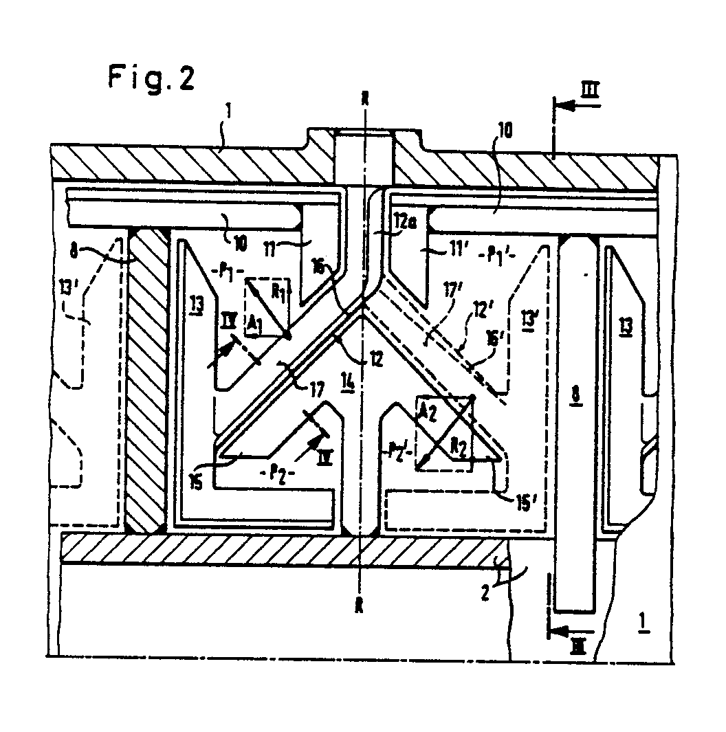
Description
Die Erfindung bezieht sich auf eine Misch- und Knetvorrichtung gemäß dem Oberbegriff des Patentanspruchs.The invention relates to a mixing and kneading device according to the preamble of the claim.
Eine Misch- und Knetvorrichtung dieser Art ist aus der DE-PS 23 49 106 bekannt, bei der sich jeweils zwischen zwei benachbarten Scheiben ein von diesen und dem Gehäuse sowie der Welle begrenzter torusförmiger Ringraum bildet, der nur in seinen Randbereichen von hakenförmigen, gehäusefesten Knet- und Schabelementen erfaßt wird. Im Inneren dieses Torusraumes ist aber eine Durchmischung der Produktes nicht gewährleistet, was zu nicht ausreichender Produkthomogenität führen kann.A mixing and kneading device of this type is known from DE-PS 23 49 106, in which a toroidal annular space, delimited by these and the housing and the shaft, is formed between each two adjacent disks and has hook-shaped, housing-fixed kneading only in its edge regions - And scraping elements is detected. However, thorough mixing of the product is not guaranteed inside this toroidal space, which can lead to insufficient product homogeneity.
Ein weiterer Nachteil kann sich dadurch ergeben, daß im Inneren des Torusraumes Produktrückstände verbleiben, die nicht ausgetragen werden können, wodurch das neu zugeführte, im Reaktor zu behandelnde Produkt geschädigt werden kann. Beim Chargenwechsel können somit unerwünschte Produktvermischungen zwischen Frisch und Fertigproduckt entstehen.A further disadvantage can result from the fact that product residues remain in the interior of the torus space that cannot be discharged, as a result of which the newly added product to be treated in the reactor can be damaged. When changing batches, undesirable product mixing between fresh and finished product can occur.
Der Efindung liegt daher die Aufgabe zugrunde, im gesamten Produkt- bzw. Reaktionsraum eine intensive Durchmischung der verschiedenen Produktkomponenten zu erzielen, wobei eine gleichmäßige Verweilzeit aller im Reaktionsraum befindlicher Produktpartikel erreicht werden soll.The invention is therefore based on the object of achieving thorough mixing of the various product components in the entire product or reaction space, with a uniform dwell time of all product particles located in the reaction space being achieved.
Diese Aufgabe wird erfindungsgemäß durch die Merkmale des Patentanspruchs 1 gelöst. Damit lassen sich neben der Gewährleistung eines kontinuierlichen axialen Produkttransports Totzonen bzw. nicht gerührte Produkträume vermeiden. Die Anordnung der pflugscharartigen Umlenkflächen sorgt darüberhinaus dafür, daß im mittleren Bereich des Torusraumes umlaufende Produktmassen ständig umgeschichtet werden und den heiz- und kühlbaren Gehäuse- und Knetwellenflächen zugeführt werden.This object is achieved by the features of
Durch eine verwundene Ausbildung der Schneidkante und der Umlenkfläche längs des vorzugsweise diagonal verlaufenden Mischarms sind die Förderkomponenten beliebig veränderbar, beispielsweise kann in Bereichen der Kneterwelle eine stärkere Steigung vorgesehen werden, um auch bei der in diesem Bereich gegebenen geringeren Umfangsgeschwindigkeit des Produktstromes ausreichende Förderkomponenten in radialer und axialer Richtung zu erhalten.Through a twisted design of the cutting edge and the deflection surface along the preferably diagonally running mixing arm, the conveying components can be changed as desired, for example, a greater slope can be provided in areas of the kneader shaft in order to ensure sufficient conveying components in radial and axial direction.
Vorzugsweise sind bei der Anordnung von mehreren in einen Torusraum ragenden Mischerarmen deren Diagonalrichtungen in Bezug auf eine radiale Achse R-R spiegelbildlich abwechselnd angeordnet, wodurch sich eine besonders wirksame Durchsetzung des Torusraumes mit Mischerarmen ergibt.In the arrangement of a plurality of mixer arms projecting into a toroidal space, their diagonal directions are alternately arranged in mirror image alternation with respect to a radial axis R-R, which results in a particularly effective enforcement of the toroidal space with mixer arms.
Um einerseits eine starke axiale Förderkomponente und andererseits eine gute Beaufschlagung der heizbaren Oberflächen des Gehäuses und der Kneterwelle zu erzielen sind die Umlenkflächen der Querschnittprofile zweier spiegelbildlich diagonal versetzt angeordneter Mischerarme derart gestaltet, daß beide Umlenkflächen Ablenkungskomponenten des Produktstroms in dieselbe Axialrichtung und in entgegengesetzt gerichtete Radialrichtung ergeben.In order to achieve a strong axial conveying component on the one hand and a good loading of the heatable surfaces of the housing and the kneader shaft on the other hand, the deflecting surfaces of the cross-sectional profiles of two mirror arms arranged diagonally offset in mirror image are designed such that both deflecting surfaces result in deflection components of the product flow in the same axial direction and in the opposite radial direction .
In einer bevorzugten Ausführungsform ragen in den radial inneren Produktraum an der Kneterwelle befestigte Zusatz-Mischarme, die in diesem Bereich für eine zusätzliche Umschichtung und Durchmischung sorgen. Vorteilhafterweise weist der Zusatz-Mischarm den diagonalen Mischerarmen in einem Scherspalt parallel zugeordnete Scherkanten auf, durch die das Produkt eine intensive Scherung und Quetschung erfährt.In a preferred embodiment, additional mixing arms fastened to the kneader shaft protrude into the radially inner product space and provide additional shifting and mixing in this area. Advantageously, the additional mixing arm has the diagonal mixer arms in parallel in a shear gap associated shear edges, through which the product experiences intensive shearing and crushing.
Der Zusatz-Mischerarm kann dabei lediglich eine Scherkante tragen oder zwei Scherkanten, die abwechselnd an den spiegelbildlich diagonal versetzten Mischerarmen vorbeigeführt werden.The additional mixer arm can only carry one shear edge or two shear edges which are alternately guided past the mixer arms which are diagonally offset in mirror image.
Zur kontinuierlichen Abreinigung der Oberflächen des Scheibenelements sowie der Kneterwelle ist am gehäusefesten Mischerarm ein L-förmiger Schaber angeordnet, von dem der eine Schenkel das Scheibenelement und der andere Schenkel die Kneterwelle abschabt.For continuous cleaning of the surfaces of the disc element and the kneader shaft, an L-shaped scraper is arranged on the mixer arm fixed to the housing, from which one leg scrapes the disc element and the other leg scrapes the kneader shaft.
Zur Abreinigung des radial stehenden Teils des Mischerarms sind an den Enden der Schaberleisten radial nach innen gerichtete Rührer angeordnet, die gleichzeitig auch noch zur Durchmischung des radial äußeren Produktraumes beitragen. Neben dem Schabe- bzw. Abreinigungseffekt bewirken die Rührer mit dem senkrecht stehenden Teil des Mischerarms auch noch eine intensive Durchrührung der in diesem Bereich befindlichen Produktmenge.To clean the radially standing part of the mixer arm, radially inwardly directed stirrers are arranged at the ends of the scraper bars, which at the same time also contribute to the mixing of the radially outer product space. In addition to the scraping or cleaning effect, the stirrers with the vertical part of the mixer arm also intensively stir the amount of product in this area.
Ein Ausführungsbeispiel der Erfindung wird nachfolgend anhand der Zeichnung näher erläutert.An embodiment of the invention is explained below with reference to the drawing.
Es zeigen
- Fig. 1 eine Misch- und Knetvorichtung mit einem aufgebrochenen Teilbereich des Gehäuses,
- Fig. 2 den aufgebrochenen Teilbereich aus Fig. 1 in vergrößertem Maßstab,
- Fig. 3 einen Schnitt durch ein Teilstück der Misch- und Knetvorrichtung gemäß der Schnittlinie III-III in Fig. 2,
- Fig. 4 einen Schnitt durch einen Mischarm und eine Scherkante gemäß Schnittlinie IV-IV in Fig. 2 und
- Fig. 5 eine andere Ausführungsform einer Misch- und Knetvorrichtung mit einem aufgebrochenen Teilbereich des Gehäuses.
- 1 is a mixing and kneading device with a broken portion of the housing,
- FIG. 2 shows the broken-open section from FIG. 1 on an enlarged scale,
- 3 shows a section through a section of the mixing and kneading device according to section line III-III in FIG. 2,
- Fig. 4 shows a section through a mixing arm and a shear edge according to section line IV-IV in Fig. 2 and
- Fig. 5 shows another embodiment of a mixing and kneading device with a broken portion of the housing.
Die Fig. 1 stellt eine Misch- und Knetvorrichtung mit einer in einem zylindrischen Gehäuse 1 koaxial angeordneten Kneterwelle 2 dar, die jeweils in einer, daß Gehäuse abschließenden Stirnwand 3 und 4 gelagert ist. Die Kneterwelle 2 durchsetzt die Stirnwand 4 und ist mit einem Antriebsaggregat 5 gekoppelt. Im Bereich der Stirnwand 4 befindet sich eine Einfüllöffnung 6 und im Bereich der Stirnwand 3 eine Auslaßöffnung 7.1 shows a mixing and kneading device with a kneader shaft 2 arranged coaxially in a
Das zylindrische Gehäuse 1 ist in einem mittleren Teilbereich aufgebrochen dargestellt, in den die Kneterwelle 2 und weitere Funktionselemente ersichtlich sind, die deutlicher aus den nachfolgend erläuterten Figuren 2 bis 4 hervorgehen.The
Die Fig. 2 zeigt das Gehäuse 1 mit darin gelagerter Kneterwelle 2, auf der in senkrecht zur Gehäuse- bzw. Kneterwellenachse liegenden Ebenen Scheibenelemente 8 angeordnet sind, die unter Einschluß eines Spaltes bis zur Gehäuseinnenwand reichen. Wie aus Fig. 3 zu ersehen, weisen die Scheibenelemente 8 eine einem Sektor von 60° entsprechende Fläche auf, wobei in einer Ebene jeweils drei Scheibenelemente 8 um 120° versetzt angeordnet sind.2 shows the
An der radial äußeren, in Bezug auf die Drehrichtung (Pfeil 9) vorderen Kante der Scheibenelemente 8 tragen diese quer verlaufende Schableisten 10, die mit der Gehäuseinnenwand einen Schabspalt einschließen und zu einer axialen Mantellinie des Gehäuses in einem Winkel angeordnet sein können. An ihren Enden tragen die Schableisten 10 radial nach innen gerichtete Rührer 11.On the radially outer, in relation to the direction of rotation (arrow 9) front edge of the
In der Gehäusewand ist mittig zwischen zwei Ebenen von Scheibenelementen 8 ein Mischerarm 12 befestigt, der in einem ersten Teilstück 12a radial nach innnen gerichtete ist und anschließend in einem Winkel von 45° zu dem in Fig. 2 linken Scheibenelement 8 abknickt. Ein weiterer, in Fig. 2 in unterbrochenen Linien dargestellter Mischerarm 12' ist zum rechten Scheibenelement 8 abgeknickt und stellt den in Umfangsrichtung nachfolgenden Mischerarm dar, der zum Zweck der Verdeutlichung in die Bildebene von Fig. 2 geschwenkt ist. Vorzugsweise sind, in Umfangsrichtung um jeweils 180° versetzt, zwei Mischerarme mit wechselnder Abknickrichtung angeordnet.A
An ihren Enden tragen die Mischerarme 12, 12' L-förmige Schaber 13, 13' von denen jeweils der eine Schenkel der Oberfläche der Scheibenelemente 8 und der andere Schenkel der Oberfläche der Kneterwelle 2 zugeordnet ist.At their ends, the
Die Abgewinkelten Mischerarme 12, 12' unterteilen den von der Innenfläche des Gehäuses 1, der Kneterwelle 2 sowie den axial nebeneinanderliegenden Scheibenelementen 8 umschlossenen Torusraum in einen radial äußeren Produktraum P₁, P₁' und einen radial inneren Produktraum P₂, P₂'.The
An der Kneterwelle 2 sind in der Ebene zwischen zwei axial benachbarten Scheibenelementen 8 mehrere, vorzugsweise zwei als Zusatz-Mischerarme vorgesehene Mischerarme 14 befestigt, die den diagonal in den Torusraum ragenden Mischerarmen 12, 12' in einem Scherspaltabstand parallel zugeordnete Scherkanten 15, 15' aufweisen.Attached to the kneader shaft 2 in the plane between two axially
Die Fig. 4 zeigt die Querschnittsflächen eines Mischerarmes 12 und einer Scherkante 15, die von einem in Umfangsrichtung fließenden Produktstrom angeströmt werden, der von einer am Mischerarm 12 angeordneten Schneidkante 16 zerteilt und in einer anschließenden Umlenkfläche 17 abgelenkt wird. Der auf der anderen Seite der Schneidkante vorbeifließende Produktstrom wird von der Scherkante 15 erfaßt und während der Vorbeibewegung (Pfeil 18) am statischen Mischerarm 12 einer intensiven Quetsch- und Scherwirkung unterworfen. Dabei kann durch die Ausbildung einer Umlenkfläche 15a noch zusätzlich eine Umlenkung erzielt werden. Damit lassen sich die durch den Mischerarm 12, 12' bewirkten Strömungseffekte, noch in beliebiger Weise beeinflussen.FIG. 4 shows the cross-sectional areas of a
Die Schneidkante 16 verläuft auf dem in Fig. 2 in Vollinien dargestellten Mischerarm 12 geradlinig, wobei die Umlenkfläche 17 im radial äußeren Bereich liegt, wodurch der auf diesen Mischerarm 12 auftreffende Produktstrom eine Umlenkung mit radial nach außen gerichteter Förderkomponente R₁ und mit einer axial nach links gerichteten Förderkomponente A₁ erfährt.The
Auf dem in Fig. 2 in unterbrochenen Linien dargestellen Mischerarm 12' verläuft die Schneidkante 16' in verwundener Form, wobei die Umlenkfläche 17' im radial inneren Bereiche liegt, wodurch der auf diesen Mischerarm 12' auftreffende Produktstrom eine Umlenkung mit radial nach innen gerichteter Förderkomponente R₂ und mit der axial nach links gerichteten Förderkomponente A₂ erfährt.On the mixer arm 12 'shown in broken lines in FIG. 2, the cutting edge 16' runs in a twisted shape, the deflecting surface 17 'lying in the radially inner region, as a result of which the product stream impinging on this mixer arm 12' deflects with a radially inwardly directed conveying component R₂ and with the axially left-facing conveying component A₂.
Durch die zusammen mit der Umlenkfläche 17' verwundene Schneidkante 16' wird erreicht, daß die im radial inneren Bereich mit geringerer Umfangsgeschwindigkeit strömenden Produktmengen eine die geringere Anströmgeschwindigkeit kompensierende wirksamere Umlenkung erfahren.As a result of the cutting edge 16 'which is twisted together with the deflection surface 17', the product quantities flowing in the radially inner region with a lower peripheral speed experience a more effective deflection which compensates for the lower inflow speed.
Grundsätzlich kann die Schneidkante 16' mit der Umlenkfläche 17' auch so verwunden sein, daß der auf den Mischarm auftreffende Produktstrom mit einer Teilmenge radial nach außen und axial nach rechts und mit der anderen Teilmenge radial nach innen und axial nach links abgelenkt wird. Aufgrund der Tatsache, daß ein derartiger Mischerarm den Produktstrom in Teilströme mit entgegengesetzt gerichteten axialen Förderkomponenten aufteilt, stellt sich keine in eine axiale Austragrichtung definierte einheitliche axiale Förderkomponente ein, so daß ein Mischarm mit S-förmig verwundener Schneidkante und Umlenkfläche überwiegend zum Zweck der intensiven Durchmischung verwendet wird. Dabei ist es vorteilhaft, wenn in Umfangsrichtung jeweils Mischerarme mit unterschiedlich gerichteten Umlenkflächen aufeinanderfolgen.In principle, the cutting edge 16 'can also be twisted with the deflecting surface 17' in such a way that the product stream impinging on the mixing arm is deflected radially outwards and axially to the right with one part and radially inwards and axially to the left with the other part. Due to the fact that such a mixer arm divides the product stream into partial streams with oppositely directed axial conveying components, there is no uniform axial conveying component defined in an axial discharge direction, so that a mixing arm with an S-shape twisted cutting edge and deflection surface is mainly used for the purpose of intensive mixing. It is advantageous if mixer arms with differently directed deflection surfaces follow one another in the circumferential direction.
Die Fig. 5 zeigt in Vollinien eine weitere Ausführungsform eines am Gehäuse 1 befestigten Mischerarms 22, der zwischen zwei benachbarten Scheibenelementen 8 radial nach innen bis zur Kneterwelle 2 ragt und dort in einen L
Der in Fig. 5 in unterbrochenen Linien dargestellte Mischerarm 22' mit dem L-förmigen Schaber 23' entspricht spiegelbildlich dem in Vollinien dargestellten Mischerarm 22 und dessen Schaber 23 und ist zur Bildebene der Fig. 5 um 180° versetzt im Gehäuse angeordnet.The mixer arm 22 'shown in broken lines in FIG. 5 with the L-shaped scraper 23' corresponds in mirror image to the
Der radial verlaufende Mischerarm 22, 22' kann gleichfalls mit einer Schneidkante und einer oder zwei Umlenkflächen versehen sein, wodurch das umlaufende Produkt in radialer und/oder axialer Förderrichtung umlenkbar ist, so daß sowohl eine gute Anströmung der beheizten Flächen vom Gehäuse und Kneterwelle als auch eine einheitliche axiale Förderung des Produkts erzielbar ist.The radially extending
Die Umlenkfläche kann dabei über die radiale Erstreckung des Mischerarms 22, 22' nach Art einer Pflugschar so verwunden sein, daß sich in der oberen Hälfte eine Anströmungskomponente in Richtung des Gehäuses und in der unten Hälfte eine Anströmungskomponente in Richtung der Kneterwelle einstellt, wobei aber bei beiden Hälften eine einheitliche, in Transportrichtung weisende axiale Strömungskomponente gegeben ist.The deflection surface can be twisted over the radial extension of the
Die dargestellten Misch- und Knetvorrichtungen sind besonders für den kontinuierlichen Betrieb geeignet, da durch die in gleiche Richtung wirkenden Axialkomponenten A₁ und A₂ dem Produkt über den gesamten Produktraum eine axiale Förderkomponente mitgeteilt wird, wobei aber auch gewährleistet ist, daß die Produktmasse aus allen Raumbereichen erfaßt, umgeschichtet und den heiz- oder kühlbaren Oberflächen des Gehäuses, der Kneterwelle und der Scheibenelemente in einer ständigen Strömung zugeführt wird.The mixing and kneading devices shown are particularly suitable for continuous operation, since the
Die erfindungsgemäße Misch- und Knetvorrichtung kann jedoch auch gleichermaßen für einen chargenweisen Betrieb genutzt werden, wenn z. B. nur Mischerarme 12 angeordnet werden, wie sie in Fig. 2 in Vollinien dargestellt sind. Damit werden ständig Produktmassen aus dem mittleren Torusbereich erfaßt und mit radialer Komponente R₁ zur heizbaren Wand des Gehäuses transportiert und mit axialer Komponente A₁ zu der Stirnwand 3 der Misch- und Knetvorrichtung gefördert. Beim Auftreffen des Produktstromes an der Stirnwand überwälzt sich dieser und strömt im radial inneren, der Kneterwelle zugeordneten Produktbereich P₂, P₂' wieder zurück, wobei der Produktstrom durch Einwirkung der als Zusatzmischerarme ausgebildeten Mischerarme 14 und der Schaber 13 weiter intensiv durchmischt wird. Die Produktentleerung erfolgt dabei vorteilhafterweise über einen in radial inneren Bereich der Stirnwand 4 gelegenen Auslaßstutzen (nicht dargestellt).However, the mixing and kneading device according to the invention can also be used equally for batch operation if, for. B. only
Claims (12)
Priority Applications (1)
| Application Number | Priority Date | Filing Date | Title |
|---|---|---|---|
| AT86114051T ATE83946T1 (en) | 1985-10-25 | 1986-10-10 | MIXING AND KNEADING DEVICE. |
Applications Claiming Priority (2)
| Application Number | Priority Date | Filing Date | Title |
|---|---|---|---|
| DE3538070 | 1985-10-25 | ||
| DE19853538070 DE3538070A1 (en) | 1985-10-25 | 1985-10-25 | MIXING AND KNEADING DEVICE |
Publications (3)
| Publication Number | Publication Date |
|---|---|
| EP0220575A2 true EP0220575A2 (en) | 1987-05-06 |
| EP0220575A3 EP0220575A3 (en) | 1989-03-29 |
| EP0220575B1 EP0220575B1 (en) | 1992-12-30 |
Family
ID=6284492
Family Applications (1)
| Application Number | Title | Priority Date | Filing Date |
|---|---|---|---|
| EP86114051A Expired - Lifetime EP0220575B1 (en) | 1985-10-25 | 1986-10-10 | Mixing and kneading device |
Country Status (5)
| Country | Link |
|---|---|
| US (1) | US4775243A (en) |
| EP (1) | EP0220575B1 (en) |
| JP (1) | JPH0649142B2 (en) |
| AT (1) | ATE83946T1 (en) |
| DE (1) | DE3538070A1 (en) |
Cited By (1)
| Publication number | Priority date | Publication date | Assignee | Title |
|---|---|---|---|---|
| WO1996022156A1 (en) * | 1995-01-18 | 1996-07-25 | List Ag | Mixing and kneading device |
Families Citing this family (14)
| Publication number | Priority date | Publication date | Assignee | Title |
|---|---|---|---|---|
| DE3635877C1 (en) * | 1986-10-22 | 1987-10-15 | Heinz Nienhaus | Mixer dryer |
| CH672749A5 (en) * | 1986-12-19 | 1989-12-29 | List Ag | |
| CH674318A5 (en) * | 1987-08-28 | 1990-05-31 | List Ag | |
| DE3743051A1 (en) * | 1987-12-18 | 1989-06-29 | Davy Mckee Ag | DEVICE FOR TREATING HIGH VISCOSITY SUBSTANCES |
| CH678285A5 (en) * | 1988-02-16 | 1991-08-30 | List Ag | |
| CH679290A5 (en) * | 1989-10-04 | 1992-01-31 | List Ag | |
| CH686406A5 (en) * | 1990-04-11 | 1996-03-29 | List Ag | Continuously operating mixing kneader. |
| DE4102177A1 (en) * | 1991-01-25 | 1992-07-30 | Krauss Maffei Ag | Stirred mixer-reactor with injection ports within series of fixed wall baffles - allowing multiple point addition, sampling, measurements along reactor length |
| DE19533693A1 (en) * | 1995-09-12 | 1997-03-13 | List Ag | Mixer kneader |
| DE19536944A1 (en) * | 1995-10-04 | 1997-04-10 | List Ag | Mixer kneader |
| US5735603A (en) * | 1996-05-03 | 1998-04-07 | Littleford Day, Inc. | Horizontal mixer apparatus and method with improved shaft and seal structure |
| US20040145964A1 (en) * | 2001-04-25 | 2004-07-29 | Alfred Kunz | Mixer bars cleaning in a radial or axial manner |
| CN203132209U (en) * | 2010-06-17 | 2013-08-14 | 爱信精机株式会社 | Dilution device for sticky substances |
| EP3180115B1 (en) | 2014-08-13 | 2018-10-24 | Versalis S.p.A. | Rotor and stirring device |
Family Cites Families (16)
| Publication number | Priority date | Publication date | Assignee | Title |
|---|---|---|---|---|
| DE422986C (en) * | 1923-02-03 | 1925-12-22 | Eduard Boehme | Mixer |
| US1587115A (en) * | 1923-08-08 | 1926-06-01 | Francis X Govers | Process and apparatus for the heat treatment of chemical compounds |
| US1585169A (en) * | 1923-10-26 | 1926-05-18 | Perkins Glue Co | Mixing kettle |
| US2991503A (en) * | 1958-01-06 | 1961-07-11 | Rietz Mfg Co | Breaking, mixing, and extrusion apparatus |
| GB979932A (en) * | 1961-05-16 | 1965-01-06 | Loedige Wilhelm | Method and apparatus for enveloping granular and/or shortfibred substances in coatings of other substances |
| US3197180A (en) * | 1963-10-11 | 1965-07-27 | Chemineer | Mixing device |
| GB1237630A (en) * | 1968-05-07 | 1971-06-30 | Ceskoslovenska Akademie Ved | Apparatus for bringing a melt or solid substances into co-current contact with hot gaseous media |
| CH583061A5 (en) | 1972-10-18 | 1976-12-31 | List Heinz | |
| JPS5136666A (en) * | 1974-09-25 | 1976-03-27 | Hitachi Ltd | Konendobutsushitsu no yokogatarenzokukonwaki |
| US4169680A (en) * | 1977-07-25 | 1979-10-02 | Amsted Industries Incorporated | Method and apparatus for making composition friction materials |
| DE2852499A1 (en) * | 1978-12-05 | 1980-06-19 | Schwing Gmbh F | MIXERS FOR DICKERS, e.g. FOR FILTER CAKE, SLUDGE OR THE LIKE |
| JPS56114823U (en) * | 1980-02-01 | 1981-09-03 | ||
| JPS56118728A (en) * | 1980-02-26 | 1981-09-17 | Fukushima Tadao | Continuous stirring apparatus |
| DE3037332C2 (en) * | 1980-10-02 | 1983-09-08 | Draiswerke Gmbh, 6800 Mannheim | Mixer for bulk material and suspensions, especially fibrous suspensions |
| CH657069A5 (en) * | 1982-10-04 | 1986-08-15 | List Ind Verfahrenstech | HEATABLE AND COOLABLE DISC STIRRERS. |
| CH661450A5 (en) | 1984-04-30 | 1987-07-31 | List Ind Verfahrenstech | Kneader mixer having counter-elements |
-
1985
- 1985-10-25 DE DE19853538070 patent/DE3538070A1/en active Granted
-
1986
- 1986-10-10 EP EP86114051A patent/EP0220575B1/en not_active Expired - Lifetime
- 1986-10-10 AT AT86114051T patent/ATE83946T1/en not_active IP Right Cessation
- 1986-10-23 JP JP61250946A patent/JPH0649142B2/en not_active Expired - Lifetime
- 1986-10-27 US US06/923,591 patent/US4775243A/en not_active Expired - Fee Related
Cited By (1)
| Publication number | Priority date | Publication date | Assignee | Title |
|---|---|---|---|---|
| WO1996022156A1 (en) * | 1995-01-18 | 1996-07-25 | List Ag | Mixing and kneading device |
Also Published As
| Publication number | Publication date |
|---|---|
| DE3538070A1 (en) | 1987-04-30 |
| EP0220575B1 (en) | 1992-12-30 |
| JPH0649142B2 (en) | 1994-06-29 |
| EP0220575A3 (en) | 1989-03-29 |
| US4775243A (en) | 1988-10-04 |
| ATE83946T1 (en) | 1993-01-15 |
| JPS62102823A (en) | 1987-05-13 |
| DE3538070C2 (en) | 1991-03-07 |
Similar Documents
| Publication | Publication Date | Title |
|---|---|---|
| EP0517068B1 (en) | Mixing kneader | |
| EP0220575A2 (en) | Mixing and kneading device | |
| EP0144092B1 (en) | Mixing and kneading machine | |
| EP0329092A1 (en) | Mixer-kneader with plural shafts | |
| DE69015577T2 (en) | Apparatus for the treatment of viscous liquids. | |
| EP0289647A1 (en) | Disc kneader | |
| EP0304925B1 (en) | Mixer having forked kneading tools | |
| WO1997012666A1 (en) | Mixing kneader | |
| EP1121193A1 (en) | Compulsory mixer used, in particular, as a cement mixer | |
| CH686229A5 (en) | Method and apparatus for continuous networks of grain and use the network device. | |
| EP0804278B1 (en) | Mixing and kneading device | |
| EP0046477A1 (en) | Device for the production of a pasty mixture | |
| EP0293452A1 (en) | Multi-axial mixing drier or reactor | |
| DE2541939A1 (en) | HORIZONTAL CONTINUOUS KNABLES FOR HIGHLY VISCOSE MATERIAL | |
| DE69401414T2 (en) | Uniform, one-piece, rotatable mixer and dispensing head | |
| DE10248333A1 (en) | Dynamic mixer | |
| EP0761295A1 (en) | Mixing kneader | |
| DE3635877C1 (en) | Mixer dryer | |
| DE3741654A1 (en) | Multi-shaft mixer drier or mixer reactor | |
| DD256460A1 (en) | GRILL CORRUGATOR SYSTEM IN STIRRING BALL MILLS | |
| DE2440461A1 (en) | Agitator for twin-shaft concrete mixer - has oppositely rotating worm bands on each shaft providing two-way passage for mixed material | |
| DE4115496C2 (en) | ||
| CH674959A5 (en) | Kneading mixer for thermal and chemical processing - agglomeration of paste is avoided by having two mixing zones and shaft with series of vaned arms which rotate between fixed kneaders | |
| CH661450A5 (en) | Kneader mixer having counter-elements | |
| DE4006214C2 (en) | Device for surface cleaning of bulk solids |
Legal Events
| Date | Code | Title | Description |
|---|---|---|---|
| PUAI | Public reference made under article 153(3) epc to a published international application that has entered the european phase |
Free format text: ORIGINAL CODE: 0009012 |
|
| AK | Designated contracting states |
Kind code of ref document: A2 Designated state(s): AT BE CH FR GB IT LI LU NL SE |
|
| PUAL | Search report despatched |
Free format text: ORIGINAL CODE: 0009013 |
|
| AK | Designated contracting states |
Kind code of ref document: A3 Designated state(s): AT BE CH FR GB IT LI LU NL SE |
|
| 17P | Request for examination filed |
Effective date: 19890522 |
|
| 17Q | First examination report despatched |
Effective date: 19900606 |
|
| GRAA | (expected) grant |
Free format text: ORIGINAL CODE: 0009210 |
|
| AK | Designated contracting states |
Kind code of ref document: B1 Designated state(s): AT BE CH FR GB IT LI LU NL SE |
|
| REF | Corresponds to: |
Ref document number: 83946 Country of ref document: AT Date of ref document: 19930115 Kind code of ref document: T |
|
| ET | Fr: translation filed | ||
| GBT | Gb: translation of ep patent filed (gb section 77(6)(a)/1977) |
Effective date: 19930120 |
|
| ITF | It: translation for a ep patent filed | ||
| PLBI | Opposition filed |
Free format text: ORIGINAL CODE: 0009260 |
|
| ITTA | It: last paid annual fee | ||
| 26 | Opposition filed |
Opponent name: LIST AG Effective date: 19930929 |
|
| EPTA | Lu: last paid annual fee | ||
| NLR1 | Nl: opposition has been filed with the epo |
Opponent name: LIST AG. |
|
| PGFP | Annual fee paid to national office [announced via postgrant information from national office to epo] |
Ref country code: GB Payment date: 19940920 Year of fee payment: 9 |
|
| PGFP | Annual fee paid to national office [announced via postgrant information from national office to epo] |
Ref country code: LU Payment date: 19941001 Year of fee payment: 9 |
|
| PGFP | Annual fee paid to national office [announced via postgrant information from national office to epo] |
Ref country code: SE Payment date: 19941011 Year of fee payment: 9 Ref country code: BE Payment date: 19941011 Year of fee payment: 9 Ref country code: AT Payment date: 19941011 Year of fee payment: 9 |
|
| PGFP | Annual fee paid to national office [announced via postgrant information from national office to epo] |
Ref country code: NL Payment date: 19941031 Year of fee payment: 9 |
|
| PGFP | Annual fee paid to national office [announced via postgrant information from national office to epo] |
Ref country code: CH Payment date: 19941111 Year of fee payment: 9 |
|
| EAL | Se: european patent in force in sweden |
Ref document number: 86114051.5 |
|
| PLBN | Opposition rejected |
Free format text: ORIGINAL CODE: 0009273 |
|
| STAA | Information on the status of an ep patent application or granted ep patent |
Free format text: STATUS: OPPOSITION REJECTED |
|
| 27O | Opposition rejected |
Effective date: 19941103 |
|
| NLR2 | Nl: decision of opposition | ||
| PG25 | Lapsed in a contracting state [announced via postgrant information from national office to epo] |
Ref country code: LU Free format text: LAPSE BECAUSE OF NON-PAYMENT OF DUE FEES Effective date: 19951010 Ref country code: GB Effective date: 19951010 Ref country code: AT Effective date: 19951010 |
|
| PG25 | Lapsed in a contracting state [announced via postgrant information from national office to epo] |
Ref country code: SE Effective date: 19951011 |
|
| PG25 | Lapsed in a contracting state [announced via postgrant information from national office to epo] |
Ref country code: LI Effective date: 19951031 Ref country code: CH Effective date: 19951031 Ref country code: BE Effective date: 19951031 |
|
| BERE | Be: lapsed |
Owner name: KRAUSS-MAFFEI A.G. Effective date: 19951031 |
|
| PGFP | Annual fee paid to national office [announced via postgrant information from national office to epo] |
Ref country code: FR Payment date: 19960430 Year of fee payment: 10 |
|
| PG25 | Lapsed in a contracting state [announced via postgrant information from national office to epo] |
Ref country code: NL Effective date: 19960501 |
|
| GBPC | Gb: european patent ceased through non-payment of renewal fee |
Effective date: 19951010 |
|
| REG | Reference to a national code |
Ref country code: CH Ref legal event code: PL |
|
| EUG | Se: european patent has lapsed |
Ref document number: 86114051.5 |
|
| NLV4 | Nl: lapsed or anulled due to non-payment of the annual fee |
Effective date: 19960501 |
|
| PG25 | Lapsed in a contracting state [announced via postgrant information from national office to epo] |
Ref country code: FR Effective date: 19970630 |
|
| REG | Reference to a national code |
Ref country code: FR Ref legal event code: ST |
|
| PG25 | Lapsed in a contracting state [announced via postgrant information from national office to epo] |
Ref country code: IT Free format text: LAPSE BECAUSE OF NON-PAYMENT OF DUE FEES;WARNING: LAPSES OF ITALIAN PATENTS WITH EFFECTIVE DATE BEFORE 2007 MAY HAVE OCCURRED AT ANY TIME BEFORE 2007. THE CORRECT EFFECTIVE DATE MAY BE DIFFERENT FROM THE ONE RECORDED. Effective date: 20051010 |
|
| PLAB | Opposition data, opponent's data or that of the opponent's representative modified |
Free format text: ORIGINAL CODE: 0009299OPPO |