EP0220595A1 - Générateur d'impulsions électromagnétiques pour débitmètres - Google Patents
Générateur d'impulsions électromagnétiques pour débitmètres Download PDFInfo
- Publication number
- EP0220595A1 EP0220595A1 EP86114189A EP86114189A EP0220595A1 EP 0220595 A1 EP0220595 A1 EP 0220595A1 EP 86114189 A EP86114189 A EP 86114189A EP 86114189 A EP86114189 A EP 86114189A EP 0220595 A1 EP0220595 A1 EP 0220595A1
- Authority
- EP
- European Patent Office
- Prior art keywords
- probe
- measuring wheel
- pulse
- hollow axis
- magnetic
- Prior art date
- Legal status (The legal status is an assumption and is not a legal conclusion. Google has not performed a legal analysis and makes no representation as to the accuracy of the status listed.)
- Granted
Links
- 239000000523 sample Substances 0.000 claims abstract description 66
- 230000008878 coupling Effects 0.000 claims description 13
- 238000010168 coupling process Methods 0.000 claims description 13
- 238000005859 coupling reaction Methods 0.000 claims description 13
- 238000003780 insertion Methods 0.000 claims description 6
- 230000037431 insertion Effects 0.000 claims description 6
- 238000009434 installation Methods 0.000 claims description 2
- 230000004308 accommodation Effects 0.000 claims 1
- 239000011796 hollow space material Substances 0.000 abstract 2
- 239000004020 conductor Substances 0.000 abstract 1
- 238000005259 measurement Methods 0.000 description 3
- 230000005540 biological transmission Effects 0.000 description 2
- IUSARDYWEPUTPN-OZBXUNDUSA-N (2r)-n-[(2s,3r)-4-[[(4s)-6-(2,2-dimethylpropyl)spiro[3,4-dihydropyrano[2,3-b]pyridine-2,1'-cyclobutane]-4-yl]amino]-3-hydroxy-1-[3-(1,3-thiazol-2-yl)phenyl]butan-2-yl]-2-methoxypropanamide Chemical compound C([C@H](NC(=O)[C@@H](C)OC)[C@H](O)CN[C@@H]1C2=CC(CC(C)(C)C)=CN=C2OC2(CCC2)C1)C(C=1)=CC=CC=1C1=NC=CS1 IUSARDYWEPUTPN-OZBXUNDUSA-N 0.000 description 1
- UDQTXCHQKHIQMH-KYGLGHNPSA-N (3ar,5s,6s,7r,7ar)-5-(difluoromethyl)-2-(ethylamino)-5,6,7,7a-tetrahydro-3ah-pyrano[3,2-d][1,3]thiazole-6,7-diol Chemical compound S1C(NCC)=N[C@H]2[C@@H]1O[C@H](C(F)F)[C@@H](O)[C@@H]2O UDQTXCHQKHIQMH-KYGLGHNPSA-N 0.000 description 1
- 238000005266 casting Methods 0.000 description 1
- 229940125807 compound 37 Drugs 0.000 description 1
- 229940125936 compound 42 Drugs 0.000 description 1
- 238000001514 detection method Methods 0.000 description 1
- 238000005516 engineering process Methods 0.000 description 1
- 230000002349 favourable effect Effects 0.000 description 1
- 230000005669 field effect Effects 0.000 description 1
- 238000004519 manufacturing process Methods 0.000 description 1
- 230000009347 mechanical transmission Effects 0.000 description 1
- 238000007789 sealing Methods 0.000 description 1
- 238000005476 soldering Methods 0.000 description 1
Images


Classifications
-
- G—PHYSICS
- G01—MEASURING; TESTING
- G01P—MEASURING LINEAR OR ANGULAR SPEED, ACCELERATION, DECELERATION, OR SHOCK; INDICATING PRESENCE, ABSENCE, OR DIRECTION, OF MOVEMENT
- G01P3/00—Measuring linear or angular speed; Measuring differences of linear or angular speeds
- G01P3/42—Devices characterised by the use of electric or magnetic means
- G01P3/44—Devices characterised by the use of electric or magnetic means for measuring angular speed
- G01P3/48—Devices characterised by the use of electric or magnetic means for measuring angular speed by measuring frequency of generated current or voltage
- G01P3/481—Devices characterised by the use of electric or magnetic means for measuring angular speed by measuring frequency of generated current or voltage of pulse signals
- G01P3/4815—Devices characterised by the use of electric or magnetic means for measuring angular speed by measuring frequency of generated current or voltage of pulse signals using a pulse wire sensor, e.g. Wiegand wire
-
- G—PHYSICS
- G01—MEASURING; TESTING
- G01F—MEASURING VOLUME, VOLUME FLOW, MASS FLOW OR LIQUID LEVEL; METERING BY VOLUME
- G01F15/00—Details of, or accessories for, apparatus of groups G01F1/00 - G01F13/00 insofar as such details or appliances are not adapted to particular types of such apparatus
- G01F15/06—Indicating or recording devices
- G01F15/061—Indicating or recording devices for remote indication
- G01F15/063—Indicating or recording devices for remote indication using electrical means
Definitions
- the invention relates to an electromagnetic pulse pickup for flow meters, in particular larger nominal widths, in which a measuring wheel rotating in the measuring chamber carries a magnetic device and, outside the pressure chamber, a sensor working according to the Wiegand principle with a large number of pulse wires arranged in the longitudinal direction and running on a cylindrical surface is provided, with each revolution of the measuring wheel magnetic pulses are generated, which are converted in a concentric within the pulse wire cylinder transducer coil into voltage pulses, the number of which is a measure of the measuring medium flowing through the flow meter.
- the measuring chamber end wall to be penetrated by the magnetic field of the magnets used in the measuring wheel would have to be thick-walled due to the increasing transducer diameter for reasons of strength, so that the distance between the magnets and the impulse wires would be too large and thus a perfect function of the opening would complicate or make impossible.
- the object of the invention is to provide a simple and space-saving electromagnetic pickup for flow meters, in particular larger nominal diameters, in which, regardless of the nominal diameter, a small distance between the measuring wheel magnets and the pulse wires and thus always reliable pulse generation and the most error-free quantity measurement possible.
- the measuring wheel is rotatably mounted on a fixed axis designed as a hollow axis and a cylindrical probe is inserted into the cavity of the axis as a pulse wire sensor, the pulse pick-up can be accommodated in the smallest space inside the measuring wheel axis and insert in a simple manner from the open side of the hollow axis, so that no additional space is required for accommodating the pickup. Since the pickup is now inside the measuring wheel itself, it is also better protected against magnetic interference fields than an external pickup.
- the probe carries the pulse wire cylinder and the pick-up coil in its probe head and a cylindrical magnetic yoke concentrically within the coil cavity, which makes the sensor particularly easy to manufacture and install, and the cylindrical magnetic yoke influences the magnetic field in such a way that this between the respective magnets and the magnetic yoke running magnetic field in the area of the pulse wires by deflecting inwards and thus by corresponding concentration a be experiences particularly strong change with the angle of rotation. This enables the pulse wires to work exactly.
- the probe shaft of the pulse wire sensor is used to protect the electrical pulse lines and at the same time it carries holding elements with which the probe can be easily fixed to the meter housing at the desired insertion depth.
- the magnet arrangement consists of two magnets of opposite polarity inserted in the measuring wheel near the hollow axis and running parallel to the hollow axis, which orbit the probe head when the measuring wheel rotates and act on the pulse wires with magnetic fields of alternating direction and thereby trigger the pulses in the pulse wire sensor.
- the invention can be realized in a particularly simple manner with flow meters which carry a measuring wheel which is rotatably mounted on a fixed hollow axis and which carries an annular space for the installation of a magnetic coupling half, the interior of the magnetic coupling half being seated on a drive shaft for the counter Hollow axis is provided.
- the annular space for the magnetic coupling halves in the measuring wheel instead of the one magnetic coupling half the magnet required to act on the pulse wire sensor and instead of the other magnetic coupling half, the probe can be inserted into the interior of the hollow axis.
- the flow meter in the modular system can be equipped with no magnetic intervention either with magnetic transmission of the measuring wheel revolutions and direct display or instead of this mechanical transmission with an electromagnetic pick-up of the measuring wheel movement with remote transmission of the flow pulses.
- annular space provided for the magnetic coupling half in the measuring wheel can be exploited in a simple manner in that, according to the feature of claim 3, an equally large magnetic ring is used instead of the annular magnetic coupling half, which is magnetized in the axially parallel direction and divided into one or more pairs of zones, which alternate are magnetized in opposite directions and in different strengths.
- the hollow axis has a larger inner diameter
- a centering sleeve can also be pushed onto the probe shaft and inserted by means of retaining rings inserted in retaining grooves in order to insert the probe.
- the probe can also be used as a unit in hollow axes with different inner diameters.
- a temperature sensor for detecting the medium temperature in the measuring chamber must be provided. If the pulse wire sensor designed as a probe corresponds to times of claim 6 equipped in its interior with a temperature sensor, the signal line is led together with the signal line of the probe to the outside, so there is no need to attach a separate receiving pocket for the temperature sensor in the meter housing. Rather, the temperature sensor is now integrated in a simple and space-saving manner in the measuring center, which is favorable in terms of measurement technology, in the probe.
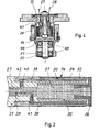
- the oval gear meter shown in FIG. 1 has the two measuring wheels 1 and 2 which are in engagement with one another via a tooth profile, which are mounted on the fixed axles 3 and 4 and rotate in the measuring chamber 6 enclosed by the housing 5.
- the measuring chamber 6 is delimited on the two end faces of the measuring wheels 1 and 2 by the end plates 7 and 8.
- the axis 4 is designed as a hollow axis, the axis cavity 9 freely in the unpressurized housing chamber 10 opens out and is closed on the other side by the closed axle end 11 to the lid space 12 which is under operating pressure.
- the pulse wire sensor 13 designed as a probe is inserted into the interior 9 of the hollow axis 4. This probe 13 has a probe head 14 with the pulse wires, the pick-up coil and a magnetic yoke and is formed in the lower region by a probe shaft 15 with the holding element 16 for fixing the probe 13 in the hollow axis 4.
- the holding element 16 is designed as a locking ring which, depending on the counter design and counter size, is inserted into one of the fixing grooves 17 of the special shaft 15.
- the hollow shaft 4 carries an internally threaded shoulder 18, into which a retaining screw 19 which clamps the locking ring 16 and thus fixes the probe 13 is screwed.
- the holding screw 19 is provided with a grub screw 20 which locks the angle setting of the probe 13.
- the probe 13 is also designed as a unit probe for insertion into the hollow axes of flow meters with different inner diameters, a centering sleeve 21 being pushed onto the probe shaft 15 when inserted into a hollow axis with a larger inner diameter. This centering bushing 21 is fixed on the probe shaft 15 by further retaining rings 22 inserted in holding grooves 17.
- the measuring wheel 2 of the flow meter rotating on the hollow axis 4 has two axially parallel bores 23 and 24, into which oppositely magnetized bar magnets 25 and 26 are inserted.
- the bar magnet 26 is made larger than the bar magnet 25 and generates a stronger magnetic field than the bar magnet 25, the two magnetic fields being opposed to one another.
- the interior of the probe shaft 15 is hollow and serves to pass the pulse connected to the pickup coil lines 27 and 28 which supply the electrical pulses generated by the pulse wires via the terminals 29 to the amplifier 30.
- the probe head 14 shown in FIG. 2 consists of the hollow cylindrical base body 31, which carries the pick-up coil 32 in its front area, which is surrounded by a magnetically non-conductive sleeve 33.
- the sleeve 33 carries longitudinal grooves distributed over the circumference, into which the pulse wires 34 are inserted and glued.
- a tubular magnetic yoke 35 is inserted into the base body 31 within the pick-up coil 32, which is secured at the free end by the plug 36 made of plastic, which also fixes the sleeve 33.
- the interior of the magnetic yoke 35 and the plug 36 is filled by a casting compound 37, which holds the plug 36 towards the front and embeds the impulse lines 27 and 28 on the probe shaft 15.
- the connecting wires 38 and 39 of the pick-up coil 32 as well as the soldering support points 40 and 41 are embedded in the probe head 14 by an external sealing compound 42.
- the hollow axis can only be made thin-walled over a small part of its length for reasons of strength.
- the probe head 14 is accommodated in this thin-walled area 43, while the thinner probe shaft 15 is inserted in the remaining, smaller diameter cavity of the axis 4.
- the probe head 14, which is enlarged in diameter compared to the probe shaft 15, also carries the pulse wires on the outside and concentrically with the pick-up coil and the magnetic yoke according to FIG over the non-expanded part of the hollow axis 4, so that the bar magnets 25 and 26 used in the measuring wheel 2 can move even closer to the probe head 14.
- the thin-walled hollow axis region 43 is closed off from the pressure side by a pressure-tight closure 46.
- the pulse wire sensor 13 with probe head 14 and probe shaft 15 is inserted into the fixed hollow axis 47 of a rotor 48.
- the rotor 48 is rotatably mounted on the stub shaft 50 via the ball bearings 49.
- the rotary drive takes place here from one of the measuring wheels via a driving fork, not shown, which engages on two opposite flattened sides 51 of the rotor 48.
Landscapes
- Physics & Mathematics (AREA)
- General Physics & Mathematics (AREA)
- Fluid Mechanics (AREA)
- Measuring Volume Flow (AREA)
Priority Applications (1)
| Application Number | Priority Date | Filing Date | Title |
|---|---|---|---|
| AT86114189T ATE60661T1 (de) | 1985-10-30 | 1986-10-14 | Elektromagnetischer impulsaufnehmer fuer durchflussmesser. |
Applications Claiming Priority (2)
| Application Number | Priority Date | Filing Date | Title |
|---|---|---|---|
| DE3538514 | 1985-10-30 | ||
| DE19853538514 DE3538514A1 (de) | 1985-10-30 | 1985-10-30 | Elektromagnetischer impulsaufnehmer fuer durchflussmesser |
Publications (2)
| Publication Number | Publication Date |
|---|---|
| EP0220595A1 true EP0220595A1 (fr) | 1987-05-06 |
| EP0220595B1 EP0220595B1 (fr) | 1991-01-30 |
Family
ID=6284765
Family Applications (1)
| Application Number | Title | Priority Date | Filing Date |
|---|---|---|---|
| EP86114189A Expired - Lifetime EP0220595B1 (fr) | 1985-10-30 | 1986-10-14 | Générateur d'impulsions électromagnétiques pour débitmètres |
Country Status (4)
| Country | Link |
|---|---|
| US (1) | US4793192A (fr) |
| EP (1) | EP0220595B1 (fr) |
| AT (1) | ATE60661T1 (fr) |
| DE (1) | DE3538514A1 (fr) |
Cited By (2)
| Publication number | Priority date | Publication date | Assignee | Title |
|---|---|---|---|---|
| EP2383547A1 (fr) * | 2010-04-30 | 2011-11-02 | Elster GmbH | Compteur de fluide |
| DE102012011716A1 (de) * | 2012-06-14 | 2013-12-19 | Bopp & Reuther Messtechnik Gmbh | Durchflussmesser für Fluide |
Families Citing this family (19)
| Publication number | Priority date | Publication date | Assignee | Title |
|---|---|---|---|---|
| US5343764A (en) * | 1986-10-28 | 1994-09-06 | The Foxboro Company | Coriolis-type mass flowmeter |
| KR960000099B1 (ko) * | 1986-10-28 | 1996-01-03 | 더폭스보로 컴패니 | 코리올리 유형의 질량유량계 |
| DE3819783A1 (de) * | 1988-06-10 | 1989-12-14 | Triumph Adler Ag | Elektronisch gesteuerte schreibmaschine, drucker od. dgl. und farbbandkassette bzw. typenradkassette hierfuer |
| DE3932735A1 (de) * | 1989-09-30 | 1991-04-18 | Dotronic Mikroprozessortechnik | Vorrichtung zum erfassen der durchflussmengen bei gaszaehlern |
| DE4114978A1 (de) * | 1991-05-08 | 1992-11-12 | Allmess Mess Regelgeraete | Fluidzaehler, insbesondere wasserzaehler |
| US5416475A (en) * | 1993-07-23 | 1995-05-16 | Schlumberger Industries, Inc. | Remote meter reading receptacle for pit lid mounting |
| US5546814A (en) * | 1994-10-26 | 1996-08-20 | The Foxboro Company | Parallel-flow coriolis-type mass flowmeter with flow-dividing manifold |
| WO1998057311A2 (fr) | 1997-06-13 | 1998-12-17 | Itron, Inc. | Systeme d'antenne de telemesures |
| US6262685B1 (en) | 1997-10-24 | 2001-07-17 | Itron, Inc. | Passive radiator |
| US6060926A (en) * | 1998-02-01 | 2000-05-09 | American Meter Company | Pulse conditioning circuit |
| US6502468B1 (en) * | 1999-12-27 | 2003-01-07 | Badger Meter, Inc. | Metering pulse transducer |
| WO2001084089A1 (fr) * | 2000-05-04 | 2001-11-08 | Schlumberger Resource Management Services, Inc. | Debitmetre muni d'un capteur de flux magnetique |
| US6604434B1 (en) | 2000-06-23 | 2003-08-12 | Neptune Technology Group, Inc. | Method and apparatus for determining the direction and rate of a rotating element |
| JP4092071B2 (ja) * | 2000-11-30 | 2008-05-28 | 三菱電機株式会社 | 半導体パワーモジュール |
| EP1474657A4 (fr) * | 2002-02-11 | 2006-05-24 | Tokheim Holding Bv | Indicateur de debit axial automatique integre a compensation thermique |
| US6886414B2 (en) * | 2003-04-21 | 2005-05-03 | Dresser, Inc. | Power generating meter |
| US6917858B2 (en) * | 2003-08-29 | 2005-07-12 | Dresser, Inc. | Fluid regulation |
| US7349813B2 (en) | 2006-05-16 | 2008-03-25 | Dresser, Inc. | Fault tolerant power system architecture for fluid flow measurement systems |
| DE102012009962A1 (de) * | 2012-05-19 | 2013-11-21 | Hengstler Gmbh | Batterieloser Zähler für strömende Medien |
Citations (3)
| Publication number | Priority date | Publication date | Assignee | Title |
|---|---|---|---|---|
| DE2157127B2 (de) * | 1970-11-19 | 1974-10-24 | Uzina De Fibre Sintetice Iasi, Iasi (Rumaenien) | Elektronischer Impulsgeber an Ovalradzählern bzw. -messern |
| DE2922252A1 (de) * | 1978-06-02 | 1979-12-06 | Kimmon Mfg Co Ltd | Stroemungsmesser mit impulsgenerator |
| DE3321952A1 (de) * | 1983-06-18 | 1984-12-20 | Bopp & Reuther Gmbh, 6800 Mannheim | Elektromagnetischer impulsaufnehmer fuer durchflussmesser |
Family Cites Families (8)
| Publication number | Priority date | Publication date | Assignee | Title |
|---|---|---|---|---|
| GB1183503A (en) * | 1967-06-16 | 1970-03-11 | Kent Ltd G | Improvements in or relating to the measurement of fluid flow |
| DE2906795A1 (de) | 1979-02-22 | 1980-09-18 | Teldix Gmbh | Impulsgeber |
| US4321495A (en) * | 1980-04-21 | 1982-03-23 | Veeder Industries, Inc. | Rotary pulse generator |
| DE8026668U1 (de) * | 1980-10-04 | 1981-01-29 | Hartig, Reiner, Dipl.-Ing., 7759 Hagnau | Fluegelradzaehler |
| DE3046804C2 (de) | 1980-12-12 | 1984-05-17 | Reiner Dipl.-Ing. 7759 Hagnau Hartig | Flügelradzähler |
| GB2102129A (en) | 1981-07-17 | 1983-01-26 | Flight Refueling Ltd | Fluid flow meters using Wiegand effect devices |
| US4553433A (en) * | 1983-05-13 | 1985-11-19 | The Singer Company | Rotary meter with integral instrument housing |
| GB8502944D0 (en) * | 1985-02-06 | 1985-03-06 | Lucas Ind Plc | In-axle vehicle wheel speed sensing device |
-
1985
- 1985-10-30 DE DE19853538514 patent/DE3538514A1/de active Granted
-
1986
- 1986-10-14 EP EP86114189A patent/EP0220595B1/fr not_active Expired - Lifetime
- 1986-10-14 AT AT86114189T patent/ATE60661T1/de not_active IP Right Cessation
- 1986-10-30 US US06/926,405 patent/US4793192A/en not_active Expired - Fee Related
Patent Citations (3)
| Publication number | Priority date | Publication date | Assignee | Title |
|---|---|---|---|---|
| DE2157127B2 (de) * | 1970-11-19 | 1974-10-24 | Uzina De Fibre Sintetice Iasi, Iasi (Rumaenien) | Elektronischer Impulsgeber an Ovalradzählern bzw. -messern |
| DE2922252A1 (de) * | 1978-06-02 | 1979-12-06 | Kimmon Mfg Co Ltd | Stroemungsmesser mit impulsgenerator |
| DE3321952A1 (de) * | 1983-06-18 | 1984-12-20 | Bopp & Reuther Gmbh, 6800 Mannheim | Elektromagnetischer impulsaufnehmer fuer durchflussmesser |
Cited By (2)
| Publication number | Priority date | Publication date | Assignee | Title |
|---|---|---|---|---|
| EP2383547A1 (fr) * | 2010-04-30 | 2011-11-02 | Elster GmbH | Compteur de fluide |
| DE102012011716A1 (de) * | 2012-06-14 | 2013-12-19 | Bopp & Reuther Messtechnik Gmbh | Durchflussmesser für Fluide |
Also Published As
| Publication number | Publication date |
|---|---|
| US4793192A (en) | 1988-12-27 |
| EP0220595B1 (fr) | 1991-01-30 |
| DE3538514C2 (fr) | 1987-10-29 |
| ATE60661T1 (de) | 1991-02-15 |
| DE3538514A1 (de) | 1987-05-07 |
Similar Documents
| Publication | Publication Date | Title |
|---|---|---|
| EP0220595B1 (fr) | Générateur d'impulsions électromagnétiques pour débitmètres | |
| DE102006060213B4 (de) | Drehwinkelsensor | |
| EP0272544B1 (fr) | Détecteur de position angulaire à disque tournant palpable par voie photoélectrique et axe de rotation à double roulement | |
| DE19917312B4 (de) | Einrichtung zur Positionserfassung | |
| EP3250890B1 (fr) | Système magnétique de mesure d'angle de rotation | |
| DE3605914A1 (de) | Magnetkupplung mit ueberwachung der drehbewegung | |
| DE3733862A1 (de) | Stroemungsanzeige- bzw. -messgeraet | |
| DE60018402T2 (de) | Verfahren und vorrichtung zur informationsübertragung und kommunikation mit einem bohrlochwerkzeug | |
| EP0638176B1 (fr) | Dispositif de mesure de mouvements de rotation | |
| EP1357365A2 (fr) | Détecteur de position | |
| EP1128159A2 (fr) | Arbre méchanique avec arrangement d'aimant intégré | |
| DE4213977A1 (de) | Vorrichtung zur messung von drehbewegungen | |
| EP0452556B1 (fr) | Capteur pour une direction assistée entraînée par moteur électrique | |
| DE4025430A1 (de) | Drehschrauberkopf | |
| EP2943798A1 (fr) | Dispositif de détection servant à mesurer la vitesse de rotation d'une roue de véhicule, système de freinage de véhicule et véhicule équipé de ce dispositif, et utilisation du dispositif de détection pour mesurer la vitesse de rotation d'une roue de véhicule | |
| DE102017113604A1 (de) | Anordnung eines Drehimpulsgebers und einer Klemmhülse zur Erfassung einer Drehzahl eines Rotors | |
| EP1471337B1 (fr) | Dispositif de mesure du niveau d'un liquide dans un contenant | |
| DE3111519C2 (de) | Mikrometerantrieb | |
| DE3124255C2 (de) | Magnetisches Sensorgerät | |
| EP1324002B1 (fr) | Dispositif pour mesurer la longueur actuelle d'un actionneur linéaire éléctromécanique | |
| EP0650058B1 (fr) | Moteur à flasque-bride avec dispositif de mesure pour la détection de la rotation d'arbre du moteur | |
| DE10006223A1 (de) | Verfahren und Vorrichtung zur Befestigung von Drehzahlmessern | |
| DE10151243C5 (de) | Umdrehungszähler | |
| DE3628278C3 (de) | Druckzylinder mit digitalem Wegmeßsystem | |
| DE3920207C2 (fr) |
Legal Events
| Date | Code | Title | Description |
|---|---|---|---|
| PUAI | Public reference made under article 153(3) epc to a published international application that has entered the european phase |
Free format text: ORIGINAL CODE: 0009012 |
|
| AK | Designated contracting states |
Kind code of ref document: A1 Designated state(s): AT BE FR GB IT NL SE |
|
| 17P | Request for examination filed |
Effective date: 19871028 |
|
| 17Q | First examination report despatched |
Effective date: 19891215 |
|
| GRAA | (expected) grant |
Free format text: ORIGINAL CODE: 0009210 |
|
| RAP1 | Party data changed (applicant data changed or rights of an application transferred) |
Owner name: BOPP & REUTHER AKTIENGESELLSCHAFT |
|
| AK | Designated contracting states |
Kind code of ref document: B1 Designated state(s): AT BE FR GB IT NL SE |
|
| REF | Corresponds to: |
Ref document number: 60661 Country of ref document: AT Date of ref document: 19910215 Kind code of ref document: T |
|
| ITF | It: translation for a ep patent filed | ||
| GBT | Gb: translation of ep patent filed (gb section 77(6)(a)/1977) | ||
| ET | Fr: translation filed | ||
| PLBI | Opposition filed |
Free format text: ORIGINAL CODE: 0009260 |
|
| 26 | Opposition filed |
Opponent name: SMITH METER GMBH Effective date: 19911030 |
|
| NLR1 | Nl: opposition has been filed with the epo |
Opponent name: SMITH METER GMBH. |
|
| PLBM | Termination of opposition procedure: date of legal effect published |
Free format text: ORIGINAL CODE: 0009276 |
|
| STAA | Information on the status of an ep patent application or granted ep patent |
Free format text: STATUS: OPPOSITION PROCEDURE CLOSED |
|
| 27C | Opposition proceedings terminated |
Effective date: 19931227 |
|
| NLR2 | Nl: decision of opposition | ||
| EAL | Se: european patent in force in sweden |
Ref document number: 86114189.3 |
|
| PGFP | Annual fee paid to national office [announced via postgrant information from national office to epo] |
Ref country code: BE Payment date: 19960705 Year of fee payment: 11 |
|
| PGFP | Annual fee paid to national office [announced via postgrant information from national office to epo] |
Ref country code: GB Payment date: 19961004 Year of fee payment: 11 |
|
| PGFP | Annual fee paid to national office [announced via postgrant information from national office to epo] |
Ref country code: SE Payment date: 19961015 Year of fee payment: 11 |
|
| PGFP | Annual fee paid to national office [announced via postgrant information from national office to epo] |
Ref country code: FR Payment date: 19961028 Year of fee payment: 11 |
|
| PGFP | Annual fee paid to national office [announced via postgrant information from national office to epo] |
Ref country code: AT Payment date: 19961030 Year of fee payment: 11 |
|
| PGFP | Annual fee paid to national office [announced via postgrant information from national office to epo] |
Ref country code: NL Payment date: 19961031 Year of fee payment: 11 |
|
| PG25 | Lapsed in a contracting state [announced via postgrant information from national office to epo] |
Ref country code: GB Free format text: LAPSE BECAUSE OF NON-PAYMENT OF DUE FEES Effective date: 19971014 Ref country code: AT Free format text: LAPSE BECAUSE OF NON-PAYMENT OF DUE FEES Effective date: 19971014 |
|
| PG25 | Lapsed in a contracting state [announced via postgrant information from national office to epo] |
Ref country code: SE Free format text: LAPSE BECAUSE OF NON-PAYMENT OF DUE FEES Effective date: 19971015 |
|
| PG25 | Lapsed in a contracting state [announced via postgrant information from national office to epo] |
Ref country code: FR Free format text: THE PATENT HAS BEEN ANNULLED BY A DECISION OF A NATIONAL AUTHORITY Effective date: 19971031 Ref country code: BE Free format text: LAPSE BECAUSE OF NON-PAYMENT OF DUE FEES Effective date: 19971031 |
|
| BERE | Be: lapsed |
Owner name: BOPP & REUTHER A.G. Effective date: 19971031 |
|
| PG25 | Lapsed in a contracting state [announced via postgrant information from national office to epo] |
Ref country code: NL Free format text: LAPSE BECAUSE OF NON-PAYMENT OF DUE FEES Effective date: 19980501 |
|
| GBPC | Gb: european patent ceased through non-payment of renewal fee |
Effective date: 19971014 |
|
| NLV4 | Nl: lapsed or anulled due to non-payment of the annual fee |
Effective date: 19980501 |
|
| EUG | Se: european patent has lapsed |
Ref document number: 86114189.3 |
|
| REG | Reference to a national code |
Ref country code: FR Ref legal event code: ST |
|
| PG25 | Lapsed in a contracting state [announced via postgrant information from national office to epo] |
Ref country code: IT Free format text: LAPSE BECAUSE OF NON-PAYMENT OF DUE FEES;WARNING: LAPSES OF ITALIAN PATENTS WITH EFFECTIVE DATE BEFORE 2007 MAY HAVE OCCURRED AT ANY TIME BEFORE 2007. THE CORRECT EFFECTIVE DATE MAY BE DIFFERENT FROM THE ONE RECORDED. Effective date: 20051014 |