EP0220607B1 - Kühlvorrichtung - Google Patents
Kühlvorrichtung Download PDFInfo
- Publication number
- EP0220607B1 EP0220607B1 EP86114259A EP86114259A EP0220607B1 EP 0220607 B1 EP0220607 B1 EP 0220607B1 EP 86114259 A EP86114259 A EP 86114259A EP 86114259 A EP86114259 A EP 86114259A EP 0220607 B1 EP0220607 B1 EP 0220607B1
- Authority
- EP
- European Patent Office
- Prior art keywords
- heat exchanger
- air
- heating
- heating heat
- housing
- Prior art date
- Legal status (The legal status is an assumption and is not a legal conclusion. Google has not performed a legal analysis and makes no representation as to the accuracy of the status listed.)
- Expired
Links
Images



Classifications
-
- F—MECHANICAL ENGINEERING; LIGHTING; HEATING; WEAPONS; BLASTING
- F28—HEAT EXCHANGE IN GENERAL
- F28B—STEAM OR VAPOUR CONDENSERS
- F28B9/00—Auxiliary systems, arrangements, or devices
- F28B9/005—Auxiliary systems, arrangements, or devices for protection against freezing
-
- F—MECHANICAL ENGINEERING; LIGHTING; HEATING; WEAPONS; BLASTING
- F28—HEAT EXCHANGE IN GENERAL
- F28B—STEAM OR VAPOUR CONDENSERS
- F28B1/00—Condensers in which the steam or vapour is separate from the cooling medium by walls, e.g. surface condenser
- F28B1/06—Condensers in which the steam or vapour is separate from the cooling medium by walls, e.g. surface condenser using air or other gas as the cooling medium
-
- F—MECHANICAL ENGINEERING; LIGHTING; HEATING; WEAPONS; BLASTING
- F28—HEAT EXCHANGE IN GENERAL
- F28B—STEAM OR VAPOUR CONDENSERS
- F28B1/00—Condensers in which the steam or vapour is separate from the cooling medium by walls, e.g. surface condenser
- F28B1/06—Condensers in which the steam or vapour is separate from the cooling medium by walls, e.g. surface condenser using air or other gas as the cooling medium
- F28B2001/065—Condensers in which the steam or vapour is separate from the cooling medium by walls, e.g. surface condenser using air or other gas as the cooling medium with secondary condenser, e.g. reflux condenser or dephlegmator
-
- Y—GENERAL TAGGING OF NEW TECHNOLOGICAL DEVELOPMENTS; GENERAL TAGGING OF CROSS-SECTIONAL TECHNOLOGIES SPANNING OVER SEVERAL SECTIONS OF THE IPC; TECHNICAL SUBJECTS COVERED BY FORMER USPC CROSS-REFERENCE ART COLLECTIONS [XRACs] AND DIGESTS
- Y10—TECHNICAL SUBJECTS COVERED BY FORMER USPC
- Y10S—TECHNICAL SUBJECTS COVERED BY FORMER USPC CROSS-REFERENCE ART COLLECTIONS [XRACs] AND DIGESTS
- Y10S165/00—Heat exchange
- Y10S165/90—Cooling towers
-
- Y—GENERAL TAGGING OF NEW TECHNOLOGICAL DEVELOPMENTS; GENERAL TAGGING OF CROSS-SECTIONAL TECHNOLOGIES SPANNING OVER SEVERAL SECTIONS OF THE IPC; TECHNICAL SUBJECTS COVERED BY FORMER USPC CROSS-REFERENCE ART COLLECTIONS [XRACs] AND DIGESTS
- Y10—TECHNICAL SUBJECTS COVERED BY FORMER USPC
- Y10S—TECHNICAL SUBJECTS COVERED BY FORMER USPC CROSS-REFERENCE ART COLLECTIONS [XRACs] AND DIGESTS
- Y10S261/00—Gas and liquid contact apparatus
- Y10S261/11—Cooling towers
Definitions
- the invention relates to a cooling apparatus operated by ambient air and by an agent to be cooled which may freeze at atmospherical temperatures, which comprises a housing such as a cooling tower or the like having air inlets and air closure means at the air inlets and great surface heat exchangers arranged within the housing at the air inlets.
- the agent is coolet by air streaming through the great surface heat exchangers which is divided into groups or sectors being in parallel connection to each other. At least, one pre- heating heat exchanger is arranged in the air space of each sector.
- the main object of the present invention is to more efficiently obviate the afore said difficulties occuring with conventional cooling apparatus and to provide a cooling apparatus as described in the introduction above which can be operated in the case of cold weather without the danger of freezing of the agent to be cooled within the heat exchanger and of interrupting the flow of the agent in the tubes of the heat exchanger.
- each pre-heating heat exchanger is in parallel connection with the great surface heat exchangers of the associated sector, and is arranged in a housing being in the air space behind the great surface heat exchanger, this housing comprising air closure means at at least one air opening of the housing.
- the cooling apparatus according to the invention thus enables the great surface heat exchangers to be filled up or emptied even in cold weather without the danger of damages resulting from freezing of the agent to be cooled.
- an air ventilator is provided in the housing of the pre- heating heat exchanger, and the air closure means of the housing may be arranged at the suction side of the ventilator.
- a heating means can be arranged between the air inlet of the housing of the pre-heating heat exchanger and the pre-heating heat exchanger, the heating means being supplied with the heating energy which is independent of the great surface heat exchanger and/or on the pre-heating heat exchanger.
- the air space of the mentioned heating means can be seperated from the air space of the pre-heating heat exchanger by a partion wall which forms, with a part of the wall of the housing of the pre-heating heat exchanger, a channel bypassing the air space of the pre-heating heat exchanger, one end of which being provided with air closure means.
- the ventilator is arranged in the common air space of the heating means and the pre-heating heat exchanger.
- a water distributor system for humidifying the outer surface of the pre- heating heat exchanger can be provided in the housing of the pre-heating heat exchangers.
- the water distributor system can comprise a plurality of nozzles fed by a pump from a container arranged below the pre-heating heat exchanger, for collecting the water falling down from the heat exchanger, as well as a valve controlling the water level within the container and an emptying conduit connected to the container.
- shut off means and valves are provided on suitable places and in sufficient number in the whole apparatus.
- a shut off valve driven by an actuator can be provided in the supply conduit of each pre-heating heat exchanger and the actuators are operatively connected to a control unit for operating them in dependency on the temperatures in a return conduit of the great surface heat exchangers and in a return conduit of the pre-heating heat exchanger.
- the aperture of the valves are controlled for minimizing the difference between the temperatures in the return conduit of the great surface heat exchangers and the return conduit of the pre-heating heat exchanger.
- FIG. 1 The schematic circuit diagram of a conventional cooling apparatus is represented in Figure 1.
- an indirect cooling tower 100 with artificial draught having water as an agent to be cooled is shown.
- other types of cooling apparatus can find utilization in connection with this invention.
- Warm water to be recooled arrives through a supply conduit 1 and a shut-off valve 2 into a heat exchanger 3 having a great surface on the air because of a plurality of fins or ribs fixed to the tubes of the heat exchanger 3.
- the water rises in the tubes into an upper water chamber 5 and further descends through tubes 6 and a shut-off valve 7 into a collecting line or return conduit 8. Resulting from the enlargened surface of the heat exchanger 3, the heat exchange on the air side of it is very intensive.
- Great surface heat exchangers 3 are arranged in a housing, in this example in the cooling tower 100 forming a circle in the vincinity of air inlets of the cooling tower 100. More of neighboring heat exchangers 3 are parallelly connected to each other for forming groups or sectors. These sectors are connected to supply conduit 1 and to return conduit 8 by a common shut-off valve 2 and 7, respectively. As it is usual in the praxis, six to eight sectors are in a cooling tower and each sector contains twenty to fifty heat exchangers 3 connected in parallel to one another.
- artificial draught is used in this example which is established by a ventilator 10 arranged in cooling tower 100, e.g. in its upper chimney portion.
- the intensity of the draught can be controlled by air closure means such as louvers 11 at the air inlets of cooling tower 100.
- an air escape and inlet valve 15 is connected to upper water chamber 5 of heat exchangers 3. Further to this, a valve 16 is provided between supply conduit 1 and return conduit 8 for permitting water to by-pass heat exchangers 3.
- the mass of the metallic materiral of heat exchangers 3 is five to twenty times greater than the mass of the water contained in the heat exchangers 3, thus, the material of the heat exchangers has a great heat storage capacity in relation to the heat storage capacity of the water contained in it.
- the heat exchangers 3 cool down to the ambient air temperature and, what is more, within a very short time because of the great surface on the air side.
- heat exchangers 3 as high as 15 to 20 meters are built, thus, also in the case of closed louvers 11, a considerable air flow cools the air side of the heat exchangers 3.
- the flow resistance for the air stream is low.
- the conventional cooling towers as described above can be safely repeatedly started and stopped with ambient temperatures not lower than 5 to 8 degrees centigrade below zero.
- the danger of deformations, demolition or even rupture the heat exchangers 3 has to be taken into consideration due to of freezing of the water and/or due to temperature strains.
- valves 2 and 7 opened simultaneously, thus, the water flows from conduits 1 and 8 into the sectors and heat exchangers 3 and the air escapes through valve 15.
- the water streams upwards in the forward side and in the return side through tubes with relatively small diameters.
- the metallic material of the heat exchangers 3 dissipates such an amount of heat from the water, that it may freeze partly or totally. The ice plugs close the tubes, and, thus, the water circulation is counteracted.
- an auxiliary heat source such as a hot air generator operated with electrical energy or with oil is usually provided in a space portion 18 between the heat exchangers 3 and the louvers 11. They have a considerable energy demand which have to be delivered to the cooling towers. This is often difficult if not impossible to realize and in expensive.
- Valves 2 and 7 will be closed and valve 12 opened. From a heat exchanger 3 with avarage measurements, the water flows out in 30 to 50 seconds. Since the metallic parts of the heat exchangers 3 have a higher temperature than the ambient air, a natural draught is present also after the emptying for a certain period of time. Because of the strong cooling effect, the water remaining on the inner surface of the heat exchanger 3 gets frozen and it forms ice plugs which shut the water flow during the next starting of the heat exchangers.
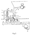
- At least one pre-heating heat exchanger 20 is provided in the air space 29 of each sector of heat exchangers 3 which is connected through valves 21 and 22 to supply conduit 1 and return conduit 8, respectively.
- preheating heat exchangers 20 are in parallel connection with heat exchangers 3.
- Emptying valves 27 are provided also for pre- heating heat exchanger 20.
- Pre-heating heat exchanger 20 in Fig. 2 is arranged in a housing 17 which is in the air space 29 of great surface heat exchangers 3.
- a housing 17 which is in the air space 29 of great surface heat exchangers 3.
- an air closing means such as louvers 19, and in the vincinity, within housing 17, an air forcing means such as a ventilator 24 are arranged.
- the other opening of housing 17 is connected to the air space portion 18 between heat exchangers 3 and louvers 11.
- the tubes of pre-heating heat exchanger 20 are considerably shorter than that of great surface heat exchangers 3.
- the longitudinal size and the metal weight of pre-heating heat exchangers 20 are chosen to be small, e.g. they are three times to four times smaller than that of the heat exchangers 3.
- the heating energy is provided by the water to be recooled which is circulated in conduits 1 and 8.
- pre-heating heat exchanger 20 can be connected to the cooling circuit when the water reaches a temperature of 10 to 15 degrees centigrade. Heat exchangers 20 can be filled up without any danger of freezing, since their tubes are relatively short and they are arranged within air chamber 23 of housing 17 and if louvers 19 are closed, there is practically no air stream which could cool them.
- louvers 19 will be opened and ventilator 24 will be started to suck air through louvers 19 and to press it through pre-heating heat exchanger 20 into air space portion 18. Thereafter, the warm air will flow through heat exchanger 3 and the latter will be warmed up. Further, the air can be sucked back into air chamber 23 by ventilator 24 as indicated by an arrow 25.
- heat exchangers 3 can be stopped (emptied) as follows:
- louvers 11 are first closed and ventilator 24 in housing 17 is started for pressing air into air portion 18. Thereafter, valves 2 and 7 of heat exchangers 3 are closed and emptying valve 12 is opened. Now, the water flows out from the tubes of heat exchanger 3. In this period and up to 10 to 15 minutes later ventilator 24 forces warm air through great surface heat exchanger 3, and the freezing of the water is prevented. Thereafter, ventilator 24 can be stopped and pre-heating heat exchanger 20 can be emptied by closing valves 21 and 22 and opening valve 27.
- housing 17 is connected to air space portion 18 between louvers 11 and great surface heat exchangers 3.
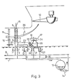
- pre-heating heat exchangers 20 can also be used for cooling purposes as shown in Fig. 3.
- the main stream of air flows through great surface heat exchanger 3 as indicated by arrow 9, but an auxiliar air flow can be established through air chamber 23 and heat exchanger 20 as shown by arrows 39.
- This air flow can be promoted by ventilator 24 driven for sucking air through air chamber 23.
- ventilator 24 it is preferable to use a ventilator 24 with re- versable rotational direction.
- an air closing means such as louvers 28 can be provided for closing the air space of each sector of great surface heat exchangers 3 towards the chimney portion of cooling tower 100.
- louvers 11 and 18 limiting the air of the sector from both sides are closed and the air pre-heating great surface heat exchangers 3 is recirculated within the air space of the sector.
- FIG. 5 an embodiment of this invention with two stage pre-heating is shown.
- An inner circuit of air circulation is established within housing 17 as shown by an arrow 32 in which a heating means such as an electrical heater 30 is provided. It is important that the heating means is supplied from an energy source being independent from the water to be recooled.
- An air space 26 of electrical heater 30 and pre-heating exchanger 20 is separated from air chamber 23 of housing 17 by a partition wall 50 which formes a channel 41 being closable by e.g. louvers 40.
- Ventilator 24 is arranged with in air space 26 which can be closed by e.g. louvers 31 at its opening towards air space portion 18.
- louvers 11, 19, 31 and 40 are closed and electrical heater 30 is energized.
- louvers 40 are opened and ventilator 24 is switched on for pressing air through heat exchanger 20 and heater 30. With this, the inner circulation as shown by arrow 32 will be established.
- pre-heating heat exchanger 20 can be filled up with water and the filling operation of great surface heat exchanger 3 can be continued as usually.
- pre-heating exchanger 20 can provide also the recooling function of cooling tower 100 if necessary in hot weather.
- the heat transmissing capacity of these heat exchangers 20 can be enlargened when their surface are humidified, and with this, at least partially, evaporation cooling is realized.
- An embodiment of the invention for these purposes is illustrated in Fig. 6.
- a water distribution system is provided comprising a plurality of water spray nozzles 33 fed by a pump 34. Below heat exchanger 20, a container 35 collecting the water dropping from heat exchanger 20 is arranged to which pump 34 is connected.
- the water evaporating from the surface of heat exchanger 20 is led through a conduit 36 having a valve 38, controlling the water level within container 35.
- the collected water is led out through a conduit 37.
- the cooling efficiency of heat exchange 20 can be extended to two or three times of that of the embodiment without the water distribution system, depending on the humidity content of the ambient air.
- heat exchangers 20 having relatively small heat exchange surfaces can supply 20 to 30 percent of the whole cooling capacity of cooling tower 100 in summer time.
- Pre-heating heat exchangers 20 are described above have relatively short tubes with relatively great diameters for having low streaming resistance on the water side. Therefore, the special water forwarding capacity of heat exchangers 20 are much greater than that of great surface heat exchanger 3. This feature is advantageous as described above for filling and emptying the heat exchangers 3. However, in the summer, in warm weather, the great water forwarding capacity of heat exchangers 20 are not so advantageous in their cooling function in that time, since the water streaming through them can not be sufficiently rec- coled and the water leaving them will be warmer than the water recooled in great surface heat exchangers 3 connected in parallel to heat exchangers 20.
- the water delivered through supply conduit 1 should be recooled to the same extent in both of pre-heating heat exchangers 20 and great surface heat exchangers 3.
- Fig. 7 An embodiment is shown in Fig. 7.
- valves 21 connecting pre-heating heat exchangers 20 to supply conduit 1 are remote-controlled, for the purpose of which an actuator 46 is attached to each valve 21.
- Actuators 46 are operatively connected to a control unit 42 for operating them in dependency on the water temperature in the return conduit 8 as well as in the return conduit of pre-heating heat exchanger 20 behind valve 22.
- a temperature sensor 43 is provided in return conduit 8 and another temperature sensor 45 is arranged in the return conduit of heat exchanger 20 between its junction to return conduit 8 and valve 22.
- the required operation mode is given from a central control unit of the power plant of from a hand switch by which the pre- heating operation or cooling operation in the summer are chosen.
- valve 21 will be entirely opened by actuator 46 driven by a signal received from control unit 42.
- valve 21 will be closed by actuator 46 until the temperature in the return conduit of heat exchanger 20 at sensor 45 is the same as in return conduit 8 at sensor 43.
- the signals delivered by sensors 43 and 45 are compared in control unit 42 and in dependency on this comparison, actuator 46 will be driven by the signals of control unit 42.
- sensors 43, 35 and control unit 42 can be replaced by a three-way valve 21 in the supply conduit of pre-heating heat exchangers 20.
- three-way valve 21 In pre-heating operation, three-way valve 21 is entirely opened, in the summer, in cooling operation, it is partially opened, and in operational interrupts of the cooling tower 100, it is entirely closed by actuator 46.
Landscapes
- Engineering & Computer Science (AREA)
- Mechanical Engineering (AREA)
- General Engineering & Computer Science (AREA)
- Heat-Exchange Devices With Radiators And Conduit Assemblies (AREA)
- Devices That Are Associated With Refrigeration Equipment (AREA)
- Physical Or Chemical Processes And Apparatus (AREA)
- Turbine Rotor Nozzle Sealing (AREA)
- Superconductors And Manufacturing Methods Therefor (AREA)
- Cooling Or The Like Of Electrical Apparatus (AREA)
- Ladders (AREA)
- Acyclic And Carbocyclic Compounds In Medicinal Compositions (AREA)
Claims (8)
Priority Applications (1)
| Application Number | Priority Date | Filing Date | Title |
|---|---|---|---|
| AT86114259T ATE46030T1 (de) | 1985-10-24 | 1986-10-15 | Kuehlvorrichtung. |
Applications Claiming Priority (2)
| Application Number | Priority Date | Filing Date | Title |
|---|---|---|---|
| HU854101A HU193135B (en) | 1985-10-24 | 1985-10-24 | Auxiliary plant for operating air-cooled equipments particularly preventing winter injuries and air-cooled cooling tower provided with such auxiliary plant |
| HU410185 | 1985-10-24 |
Publications (2)
| Publication Number | Publication Date |
|---|---|
| EP0220607A1 EP0220607A1 (de) | 1987-05-06 |
| EP0220607B1 true EP0220607B1 (de) | 1989-08-30 |
Family
ID=10966900
Family Applications (1)
| Application Number | Title | Priority Date | Filing Date |
|---|---|---|---|
| EP86114259A Expired EP0220607B1 (de) | 1985-10-24 | 1986-10-15 | Kühlvorrichtung |
Country Status (12)
| Country | Link |
|---|---|
| US (1) | US4747980A (de) |
| EP (1) | EP0220607B1 (de) |
| AT (1) | ATE46030T1 (de) |
| CA (1) | CA1278195C (de) |
| CS (1) | CS258145B2 (de) |
| DE (1) | DE3665359D1 (de) |
| ES (1) | ES2010501B3 (de) |
| GR (1) | GR3000142T3 (de) |
| HU (1) | HU193135B (de) |
| PL (1) | PL159174B1 (de) |
| SU (1) | SU1514250A3 (de) |
| UA (1) | UA5940A1 (de) |
Cited By (3)
| Publication number | Priority date | Publication date | Assignee | Title |
|---|---|---|---|---|
| WO2010050820A1 (en) * | 2008-10-28 | 2010-05-06 | Statoil Asa | Air cooled heat exchanger |
| US9476648B2 (en) | 2014-01-21 | 2016-10-25 | Drexel University | Systems and methods of using phase change material in power plants |
| US10890383B2 (en) | 2014-01-21 | 2021-01-12 | Drexel University | Systems and methods of using phase change material in power plants |
Families Citing this family (23)
| Publication number | Priority date | Publication date | Assignee | Title |
|---|---|---|---|---|
| HU201997B (en) * | 1987-05-08 | 1991-01-28 | Energiagazdalkodasi Intezet | Dry cooling tower of natural draft |
| US5129456A (en) * | 1987-05-08 | 1992-07-14 | Energiagazdalkodasi Intezet | Dry-operated chimney cooling tower |
| HU205989B (en) * | 1988-05-10 | 1992-07-28 | Energiagazdalkodasi Intezet | Cooling system for condensating the dead steam of stema-turbine works particularly power-plants |
| US5427718A (en) * | 1994-02-22 | 1995-06-27 | Phelps; Peter M. | Upper and lower crossflow film fill stack for a cooling tower |
| NL1006040C2 (nl) * | 1997-05-13 | 1998-11-16 | Spray Systems Europ Agrima Sse | Luchtbevochtigingssysteem, werkwijze voor het bedrijven daarvan, alsmede toepassing daarvan voor het conditioneren van de lucht in een verf- of lakcabine. |
| US6129285A (en) * | 1998-08-11 | 2000-10-10 | Schafka; Mark Louis | System and method for air humidification |
| EP1256769A1 (de) * | 2001-05-08 | 2002-11-13 | O.Y.L. Research & Development Centre Sdn Bhd | Kühl- und/oder Heizeinheiten |
| US7434362B2 (en) | 2001-07-20 | 2008-10-14 | Unirac, Inc. | System for removably and adjustably mounting a device on a surface |
| US7600349B2 (en) | 2003-02-26 | 2009-10-13 | Unirac, Inc. | Low profile mounting system |
| US7195176B2 (en) * | 2003-10-29 | 2007-03-27 | Newman Roger R | Temperate water supply system |
| WO2005088217A1 (de) * | 2004-03-10 | 2005-09-22 | Otto Junker Gmbh | Kühlkreislaufvorrichtung |
| US9395127B2 (en) * | 2009-05-04 | 2016-07-19 | Spx Dry Cooling Usa Llc | Indirect dry cooling tower apparatus and method |
| CN102052857B (zh) * | 2009-11-03 | 2014-06-18 | 李宁 | 自然通风空冷凝汽器 |
| US8622372B2 (en) * | 2011-03-07 | 2014-01-07 | SPX Cooling Technologies | Fan cooling tower design and method |
| US8711563B2 (en) | 2011-10-25 | 2014-04-29 | International Business Machines Corporation | Dry-cooling unit with gravity-assisted coolant flow |
| HUP1200021A2 (en) * | 2012-01-12 | 2013-09-30 | Gea Egi Energiagazdalkodasi Zrt | Cooling system |
| CN102636043A (zh) * | 2012-04-16 | 2012-08-15 | 双良节能系统股份有限公司 | 干湿式联合工业循环水冷却系统 |
| CN103411442B (zh) * | 2013-06-27 | 2015-05-06 | 朱忠林 | 一种立式风冷冷凝器 |
| CA2963028C (en) * | 2014-10-13 | 2023-08-29 | Guntner GMBH & co. KG | Method of operating a heat exchanger using a communication module and a control unit |
| DE102015016330A1 (de) * | 2015-12-17 | 2017-06-22 | Eisenmann Se | Zuluftanlage |
| DE102019110237A1 (de) | 2019-04-18 | 2020-10-22 | Güntner Gmbh & Co. Kg | Wärmeübertrageranordnung mit wenigstens einem Mehrpass-Wärmeübertrager und Verfahren zum Betrieb einer Wärmeübertrageranordnung |
| DE102019110236A1 (de) * | 2019-04-18 | 2020-10-22 | Güntner Gmbh & Co. Kg | Wärmeübertrageranordnung mit wenigstens einem Mehrpass-Wärmeübertrager und Verfahren zum Betrieb einer Wärmeübertrageranordnung |
| US12247520B2 (en) * | 2020-06-16 | 2025-03-11 | Ge Infrastructure Technology Llc | Wet dry integrated circulation cooling system |
Family Cites Families (15)
| Publication number | Priority date | Publication date | Assignee | Title |
|---|---|---|---|---|
| DE1263789B (de) * | 1959-03-06 | 1968-03-21 | Gea Luftkuehler Happel Gmbh | Luftgekuehlter Oberflaechenkondensator |
| US3384165A (en) * | 1966-02-03 | 1968-05-21 | Du Pont | Heat exchanger |
| US3443633A (en) * | 1967-03-30 | 1969-05-13 | Gen Electric | Temperature compensated air-cooled steam condenser |
| US3923935A (en) * | 1971-01-25 | 1975-12-02 | Marley Co | Parallel air path wet-dry water cooling tower |
| DE2108615B2 (de) * | 1971-02-24 | 1978-03-02 | Kraftwerk Union Ag, 4330 Muelheim | Luftgekühlte Kondensationseinrichtung |
| HU165035B (de) * | 1971-11-05 | 1974-06-28 | ||
| HU165521B (de) * | 1972-07-03 | 1974-09-28 | ||
| US3925523A (en) * | 1973-11-12 | 1975-12-09 | Marley Co | Opposed air path wet-dry cooling tower and method |
| US3982914A (en) * | 1974-03-07 | 1976-09-28 | Westinghouse Electric Corporation | Drift eliminators for evaporative cooling towers |
| JPS5449403A (en) * | 1977-09-28 | 1979-04-18 | Takuma Co Ltd | Device for preventing air-cooled steam condenser from freezing |
| EP0006412A1 (de) * | 1978-07-03 | 1980-01-09 | Hamon-Sobelco S.A. | Trockenkühlturm |
| DE2836053C3 (de) * | 1978-08-17 | 1981-04-09 | Kraftwerk Union AG, 4330 Mülheim | Steuereinrichtung für Luftklappen in einem Kühlturm mit deltaförmig angeordneten Kühlelementen |
| FR2449258A1 (fr) * | 1979-02-16 | 1980-09-12 | Cem Comp Electro Mec | Aerorefrigerant atmospherique |
| SE8007516L (sv) * | 1980-10-27 | 1982-04-28 | Svenska Flaektfabriken Ab | Forfaringssett for reglering av en utomhus anordnad angkondensor och anordning for genomforande av forfaringssettet |
| US4531576A (en) * | 1983-12-16 | 1985-07-30 | Niagara Blower Co. | Apparatus for cooling fluids |
-
1985
- 1985-10-24 HU HU854101A patent/HU193135B/hu unknown
-
1986
- 1986-10-15 EP EP86114259A patent/EP0220607B1/de not_active Expired
- 1986-10-15 DE DE8686114259T patent/DE3665359D1/de not_active Expired
- 1986-10-15 ES ES86114259T patent/ES2010501B3/es not_active Expired
- 1986-10-15 AT AT86114259T patent/ATE46030T1/de not_active IP Right Cessation
- 1986-10-17 US US06/920,708 patent/US4747980A/en not_active Expired - Lifetime
- 1986-10-23 CA CA000521188A patent/CA1278195C/en not_active Expired - Lifetime
- 1986-10-23 PL PL1986262003A patent/PL159174B1/pl unknown
- 1986-10-24 SU SU864028403A patent/SU1514250A3/ru active
- 1986-10-24 UA UA4028403A patent/UA5940A1/uk unknown
- 1986-10-24 CS CS867726A patent/CS258145B2/cs not_active IP Right Cessation
-
1989
- 1989-08-31 GR GR89400137T patent/GR3000142T3/el unknown
Cited By (3)
| Publication number | Priority date | Publication date | Assignee | Title |
|---|---|---|---|---|
| WO2010050820A1 (en) * | 2008-10-28 | 2010-05-06 | Statoil Asa | Air cooled heat exchanger |
| US9476648B2 (en) | 2014-01-21 | 2016-10-25 | Drexel University | Systems and methods of using phase change material in power plants |
| US10890383B2 (en) | 2014-01-21 | 2021-01-12 | Drexel University | Systems and methods of using phase change material in power plants |
Also Published As
| Publication number | Publication date |
|---|---|
| UA5940A1 (uk) | 1994-12-29 |
| DE3665359D1 (en) | 1989-10-05 |
| PL159174B1 (pl) | 1992-11-30 |
| CA1278195C (en) | 1990-12-27 |
| HU193135B (en) | 1987-08-28 |
| CS258145B2 (en) | 1988-07-15 |
| EP0220607A1 (de) | 1987-05-06 |
| CS772686A2 (en) | 1987-11-12 |
| ATE46030T1 (de) | 1989-09-15 |
| PL262003A1 (en) | 1988-03-17 |
| GR3000142T3 (en) | 1990-11-29 |
| SU1514250A3 (ru) | 1989-10-07 |
| US4747980A (en) | 1988-05-31 |
| ES2010501B3 (es) | 1989-11-16 |
Similar Documents
| Publication | Publication Date | Title |
|---|---|---|
| EP0220607B1 (de) | Kühlvorrichtung | |
| US3968833A (en) | Method for heat recovery in ventilation installations | |
| AU645457B2 (en) | Air pre-cooler method and apparatus | |
| US5704221A (en) | Refrigeration exchanger, method for control thereof and cooling installation including such exchanger | |
| JP2851794B2 (ja) | ガスタービン用燃焼空気予冷システム | |
| CA1274391A (en) | Heat recirculation apparatus and method | |
| US11976883B2 (en) | Heat exchanger assembly having at least one multi-pass heat exchanger and method for operating a heat exchanger assembly | |
| US20050236136A1 (en) | Heat recuperator with frost protection | |
| CN111594962A (zh) | 一种氟泵节能的间接蒸发冷却空调机组及控制方法 | |
| CN106091198A (zh) | 辐射板冷暖一体化空气调节系统 | |
| CN109900047A (zh) | 风冷冰箱 | |
| US20050072169A1 (en) | Cooling system with refrigerant for air conditioning and lowering temperature of engine | |
| US5129456A (en) | Dry-operated chimney cooling tower | |
| US4603559A (en) | Water-cooled air conditioner | |
| CN215216814U (zh) | 冰箱 | |
| NO148827B (no) | System for oppvarming og ventilasjon av gjenstander eller rom som omgis av ytterhylse | |
| CN201141735Y (zh) | 一种复合防冻空气冷却器 | |
| US7334632B2 (en) | Variable volumetric flow heat exchanger for an air-to-air heat recovery system | |
| JPH01314829A (ja) | 暖房装置 | |
| CN217503856U (zh) | 一种蒸发冷式空调机组 | |
| CN111594961B (zh) | 一种防冻型间接蒸发冷却空调机组 | |
| CN2204963Y (zh) | 多功能空调器 | |
| JPH09296736A (ja) | ガスタービン発電方法及び装置 | |
| JP2713034B2 (ja) | 吸湿液体を用いた空気調和装置および空気調和方法 | |
| CN219612378U (zh) | 一种机房机柜的间接蒸发冷却系统 |
Legal Events
| Date | Code | Title | Description |
|---|---|---|---|
| PUAI | Public reference made under article 153(3) epc to a published international application that has entered the european phase |
Free format text: ORIGINAL CODE: 0009012 |
|
| AK | Designated contracting states |
Kind code of ref document: A1 Designated state(s): AT BE CH DE ES FR GB GR IT LI LU NL SE |
|
| RIN1 | Information on inventor provided before grant (corrected) |
Inventor name: SZABO, ZOLTAN, DIPL.-ING. Inventor name: PAPP, ISTVAN, DIPL.-ING. Inventor name: BODAS, JANOS, DIPL.-ING. Inventor name: BERGMANN, GYOERGY, DIPL.-ING. Inventor name: BAKAY, ARPAD, DIPL.-ING. |
|
| RIN1 | Information on inventor provided before grant (corrected) |
Inventor name: SZABO, ZOLTAN, DIPL.-ING. Inventor name: PAPP, ISTVAN, DIPL.-ING. Inventor name: BODAS, JANOS, DIPL.-ING. Inventor name: BERGMANN, GYOERGY, DIPL.-ING. Inventor name: BAKAY, ARPAD, DIPL.-ING. |
|
| 17P | Request for examination filed |
Effective date: 19871105 |
|
| 17Q | First examination report despatched |
Effective date: 19880603 |
|
| ITF | It: translation for a ep patent filed | ||
| GRAA | (expected) grant |
Free format text: ORIGINAL CODE: 0009210 |
|
| AK | Designated contracting states |
Kind code of ref document: B1 Designated state(s): AT BE CH DE ES FR GB GR IT LI LU NL SE |
|
| REF | Corresponds to: |
Ref document number: 46030 Country of ref document: AT Date of ref document: 19890915 Kind code of ref document: T |
|
| REF | Corresponds to: |
Ref document number: 3665359 Country of ref document: DE Date of ref document: 19891005 |
|
| ET | Fr: translation filed | ||
| REG | Reference to a national code |
Ref country code: GR Ref legal event code: FG4A Free format text: 3000142 |
|
| PLBE | No opposition filed within time limit |
Free format text: ORIGINAL CODE: 0009261 |
|
| STAA | Information on the status of an ep patent application or granted ep patent |
Free format text: STATUS: NO OPPOSITION FILED WITHIN TIME LIMIT |
|
| 26N | No opposition filed | ||
| ITTA | It: last paid annual fee | ||
| EPTA | Lu: last paid annual fee | ||
| EAL | Se: european patent in force in sweden |
Ref document number: 86114259.4 |
|
| PGFP | Annual fee paid to national office [announced via postgrant information from national office to epo] |
Ref country code: BE Payment date: 19971020 Year of fee payment: 12 |
|
| PG25 | Lapsed in a contracting state [announced via postgrant information from national office to epo] |
Ref country code: BE Free format text: LAPSE BECAUSE OF NON-PAYMENT OF DUE FEES Effective date: 19981031 |
|
| BERE | Be: lapsed |
Owner name: TRANSELEKTRO MAGYAR VILLAMOSSAGI KULKERESKEDELMI Effective date: 19981031 |
|
| REG | Reference to a national code |
Ref country code: GB Ref legal event code: IF02 |
|
| PGFP | Annual fee paid to national office [announced via postgrant information from national office to epo] |
Ref country code: CH Payment date: 20020924 Year of fee payment: 17 |
|
| PGFP | Annual fee paid to national office [announced via postgrant information from national office to epo] |
Ref country code: SE Payment date: 20020927 Year of fee payment: 17 Ref country code: GR Payment date: 20020927 Year of fee payment: 17 |
|
| PGFP | Annual fee paid to national office [announced via postgrant information from national office to epo] |
Ref country code: ES Payment date: 20021011 Year of fee payment: 17 |
|
| PGFP | Annual fee paid to national office [announced via postgrant information from national office to epo] |
Ref country code: LU Payment date: 20021028 Year of fee payment: 17 Ref country code: FR Payment date: 20021028 Year of fee payment: 17 |
|
| PG25 | Lapsed in a contracting state [announced via postgrant information from national office to epo] |
Ref country code: LU Free format text: LAPSE BECAUSE OF NON-PAYMENT OF DUE FEES Effective date: 20031015 |
|
| REG | Reference to a national code |
Ref country code: GB Ref legal event code: 732E |
|
| PG25 | Lapsed in a contracting state [announced via postgrant information from national office to epo] |
Ref country code: SE Free format text: LAPSE BECAUSE OF NON-PAYMENT OF DUE FEES Effective date: 20031016 Ref country code: ES Free format text: LAPSE BECAUSE OF NON-PAYMENT OF DUE FEES Effective date: 20031016 |
|
| PG25 | Lapsed in a contracting state [announced via postgrant information from national office to epo] |
Ref country code: LI Free format text: LAPSE BECAUSE OF NON-PAYMENT OF DUE FEES Effective date: 20031031 Ref country code: CH Free format text: LAPSE BECAUSE OF NON-PAYMENT OF DUE FEES Effective date: 20031031 |
|
| NLS | Nl: assignments of ep-patents |
Owner name: EGI ENERGIAGAZDALKODASI RESZVENYTARSASAG |
|
| NLT1 | Nl: modifications of names registered in virtue of documents presented to the patent office pursuant to art. 16 a, paragraph 1 |
Owner name: TRANSELEKTRO MAGYAR KUELKERESKEDELMI VALLALAT Owner name: TRANSELEKTRO ENERGETIKAI, INGATLANFEJLESZTOE, VALL Owner name: TRANSELEKTRO ENERGETIKAI ES KOERNYEZETVEDELMI RESZ |
|
| PG25 | Lapsed in a contracting state [announced via postgrant information from national office to epo] |
Ref country code: GR Free format text: LAPSE BECAUSE OF NON-PAYMENT OF DUE FEES Effective date: 20040504 |
|
| EUG | Se: european patent has lapsed | ||
| REG | Reference to a national code |
Ref country code: CH Ref legal event code: PL |
|
| PG25 | Lapsed in a contracting state [announced via postgrant information from national office to epo] |
Ref country code: FR Free format text: LAPSE BECAUSE OF NON-PAYMENT OF DUE FEES Effective date: 20040630 |
|
| REG | Reference to a national code |
Ref country code: FR Ref legal event code: ST |
|
| PGFP | Annual fee paid to national office [announced via postgrant information from national office to epo] |
Ref country code: GB Payment date: 20041013 Year of fee payment: 19 |
|
| PGFP | Annual fee paid to national office [announced via postgrant information from national office to epo] |
Ref country code: NL Payment date: 20041025 Year of fee payment: 19 |
|
| PGFP | Annual fee paid to national office [announced via postgrant information from national office to epo] |
Ref country code: AT Payment date: 20041028 Year of fee payment: 19 |
|
| PGFP | Annual fee paid to national office [announced via postgrant information from national office to epo] |
Ref country code: DE Payment date: 20041102 Year of fee payment: 19 |
|
| REG | Reference to a national code |
Ref country code: ES Ref legal event code: FD2A Effective date: 20031016 |
|
| PG25 | Lapsed in a contracting state [announced via postgrant information from national office to epo] |
Ref country code: IT Free format text: LAPSE BECAUSE OF NON-PAYMENT OF DUE FEES;WARNING: LAPSES OF ITALIAN PATENTS WITH EFFECTIVE DATE BEFORE 2007 MAY HAVE OCCURRED AT ANY TIME BEFORE 2007. THE CORRECT EFFECTIVE DATE MAY BE DIFFERENT FROM THE ONE RECORDED. Effective date: 20051015 Ref country code: GB Free format text: LAPSE BECAUSE OF NON-PAYMENT OF DUE FEES Effective date: 20051015 Ref country code: AT Free format text: LAPSE BECAUSE OF NON-PAYMENT OF DUE FEES Effective date: 20051015 |
|
| PG25 | Lapsed in a contracting state [announced via postgrant information from national office to epo] |
Ref country code: NL Free format text: LAPSE BECAUSE OF NON-PAYMENT OF DUE FEES Effective date: 20060501 |
|
| PG25 | Lapsed in a contracting state [announced via postgrant information from national office to epo] |
Ref country code: DE Free format text: LAPSE BECAUSE OF NON-PAYMENT OF DUE FEES Effective date: 20060503 |
|
| GBPC | Gb: european patent ceased through non-payment of renewal fee |
Effective date: 20051015 |
|
| NLV4 | Nl: lapsed or anulled due to non-payment of the annual fee |
Effective date: 20060501 |