EP0220615A2 - Table variable - Google Patents
Table variable Download PDFInfo
- Publication number
- EP0220615A2 EP0220615A2 EP86114304A EP86114304A EP0220615A2 EP 0220615 A2 EP0220615 A2 EP 0220615A2 EP 86114304 A EP86114304 A EP 86114304A EP 86114304 A EP86114304 A EP 86114304A EP 0220615 A2 EP0220615 A2 EP 0220615A2
- Authority
- EP
- European Patent Office
- Prior art keywords
- plate elements
- table according
- guide channels
- elements
- connecting rods
- Prior art date
- Legal status (The legal status is an assumption and is not a legal conclusion. Google has not performed a legal analysis and makes no representation as to the accuracy of the status listed.)
- Granted
Links
- 230000000087 stabilizing effect Effects 0.000 claims abstract description 3
- 210000000078 claw Anatomy 0.000 claims description 4
- 238000002347 injection Methods 0.000 description 2
- 239000007924 injection Substances 0.000 description 2
- 239000002184 metal Substances 0.000 description 2
- 238000012986 modification Methods 0.000 description 2
- 230000004048 modification Effects 0.000 description 2
- 239000004033 plastic Substances 0.000 description 2
- 239000002131 composite material Substances 0.000 description 1
- 238000010276 construction Methods 0.000 description 1
- 238000003780 insertion Methods 0.000 description 1
- 230000037431 insertion Effects 0.000 description 1
- 210000001503 joint Anatomy 0.000 description 1
- 239000000463 material Substances 0.000 description 1
- 210000001331 nose Anatomy 0.000 description 1
- 239000002985 plastic film Substances 0.000 description 1
- 229920006255 plastic film Polymers 0.000 description 1
- 230000009466 transformation Effects 0.000 description 1
- 238000000844 transformation Methods 0.000 description 1
- 239000002023 wood Substances 0.000 description 1
Images


Classifications
-
- A—HUMAN NECESSITIES
- A47—FURNITURE; DOMESTIC ARTICLES OR APPLIANCES; COFFEE MILLS; SPICE MILLS; SUCTION CLEANERS IN GENERAL
- A47B—TABLES; DESKS; OFFICE FURNITURE; CABINETS; DRAWERS; GENERAL DETAILS OF FURNITURE
- A47B87/00—Sectional furniture, i.e. combinations of complete furniture units, e.g. assemblies of furniture units of the same kind such as linkable cabinets, tables, racks or shelf units
- A47B87/002—Combination of tables; Linking or assembling means therefor
-
- A—HUMAN NECESSITIES
- A47—FURNITURE; DOMESTIC ARTICLES OR APPLIANCES; COFFEE MILLS; SPICE MILLS; SUCTION CLEANERS IN GENERAL
- A47B—TABLES; DESKS; OFFICE FURNITURE; CABINETS; DRAWERS; GENERAL DETAILS OF FURNITURE
- A47B1/00—Extensible tables
- A47B1/08—Extensible tables with extensible frames or with additional legs
-
- A—HUMAN NECESSITIES
- A47—FURNITURE; DOMESTIC ARTICLES OR APPLIANCES; COFFEE MILLS; SPICE MILLS; SUCTION CLEANERS IN GENERAL
- A47B—TABLES; DESKS; OFFICE FURNITURE; CABINETS; DRAWERS; GENERAL DETAILS OF FURNITURE
- A47B91/00—Feet for furniture in general
- A47B91/02—Adjustable feet
- A47B91/022—Adjustable feet using screw means
Definitions
- the invention relates to a variable table with a table top consisting of composite table elements, with table legs arranged on the undersides of the table elements and with connecting members for the table top plate elements.
- the object is achieved in that rectilinear guide channels are provided on the underside of the plate elements, that the connecting links separately as straight, in the guide channels insertable and longitudinally displaceable connecting rods are formed, and that the plate elements have locking members for locking the connecting rods in the guide channels and stabilizing the table.
- variable table 1 shown in Fig. 1 consists of two semicircular plate elements 2 and 3, which are joined together along a circle diameter with the help of connecting links to be described.
- Table legs 4, 5, 6, 7 are arranged on the plate elements 2, 3.
- the guide channels 9, 11 are formed on most of their longitudinal extent as a completely closed tunnel and have a rectangular inner cross-sectional profile.
- the connecting rods 13, 14 are designed as metal tubes and have a rectangular outer cross-sectional profile, which corresponds to the inner cross-sectional profile of the guide channels, so that the connecting rods are longitudinally displaceable in the guide channels.
- the guide rods 13, 14 are designed as separate parts which can be inserted into the guide channels 9, 11 and can be removed from them.
- the connecting rods 13, 14, which are inherently displaceable in the guide channels 9, 11, can be locked in certain positions by locking members.
- This lock also serves to stabilize the table composed of several plate elements.
- a clamping claw 15 is provided, which is fastened with a screw 16 to the plate element 2 and with its free end 17 presses against a flat side of the connecting rod 13, so that it is prevented from moving. After loosening the screws 16, the connecting rod 13 can be moved, brought into a new position and in turn can be fixed there by the claw 15.
- a toggle 19 is pivotally mounted on a pin 18 provided on the plate element 2, which in a conventional manner has a pressing surface 21 which is arranged eccentrically to the pin 18 and with which it can be pressed against a flank of the connecting rod 14 .
- the connecting rod 14 can thus be fixed in the guide channel 11 by correspondingly pivoting the toggle 19. After loosening the toggle 19, the rod 14 can be moved, brought into a new position and locked there again by pivoting the toggle 19. (See also Fig. 10).
- each plate element 2 On the straight side 12 of each plate element 2, 3 projecting pins 22, 23 are formed, which fit into corresponding recesses 24 and 25 of an adjacent plate element (see also Fig. 4).
- the table legs 4 to 7 are first screwed to the respective plate elements 2, 3. Subsequently, two connecting rods 13, 14 are inserted into the guide channels 9, 11 of one plate element 2 and locked there by means of the locking members 15 or 19 that they protrude a bit beyond the straight side 12, at least to the extent that they are separated from the Locking elements 15 or 19 of an adjacent plate element can be detected. Now the two plate elements 2, 3 by inserting the protruding pieces of the connecting rods 13, 14 in the guide channels in question are joined and firmly connected to one another by actuating the locking members, so that the circular table shown in FIG. 1 results.
- the circular table according to FIG. 1 can be transformed into an approximately oval table according to FIG. 2 by inserting a rectangular plate element 26 between the plate elements 2 and 3.
- 5 shows the underside of the rectangular plate element 26, on which in turn guide channels 27, 28 are provided for receiving the connecting rods 13, 14.
- the guide channels 27, 28 are not closed in the manner of a tunnel all around, but rather are designed as channels which are open downwards over their entire longitudinal extent.
- the rectangular plate element 26 can be easily inserted and removed between two correspondingly widely spread plate elements 2, 3 connected by the connecting rods 13, 14.
- locking elements in the form of the claws 15 can also be provided on the underside of the plate element 26 (FIG. 5), which fix the plate element 26 relative to the rods 13, 14 lock, which in turn are determined by the locking elements 15 or 19 provided on the plate elements 2, 3.
- the connecting rods 13, 14 advantageously have a length such that they from the 1 completely fill the guide channels 9, 11 on both plate elements 2, 3 and - as shown in Fig. 3 - extend approximately to the circular edge of these elements.
- the connecting rods 9, 11 are long enough to be able to pull apart the two plate elements 2, 3 as shown in FIG. 2 for the purpose of inserting the rectangular plate element 26, but both connecting rods 9, 11 by the locking elements 19 on both plate elements 2 , 3 can still be locked.
- the tunnel-like closed guide channels 9, 11 have longitudinal slots 29 on their undersides.
- resilient locking elements 31 are provided, the construction of which can be seen in FIG. 9.
- the internally hollow connecting rods 13 have holes 32 near their ends, in which cylindrical locking pins 33 are inserted.
- the locking pins 33 are firmly connected on their rear side to one leg 34 of a V-shaped spring 35, the other leg 36 of which is supported on the inner wall of the connecting rod 13 opposite the bore 32.
- the locking pin 33 is resiliently held within the bore 32 and can be pressed so far into the interior of the rod 13 that its top is flush with the outside of the connecting rod 13.
- the connecting rod 13 When the locking pin 33 is pressed in, the connecting rod 13 can be inserted into the associated Guide channel 9 are inserted. After a correspondingly long insertion, the locking pin 33 snaps out again in the area of the longitudinal slot 29, so that the connecting rod 13 is now displaceable in the area of the longitudinal slot 29, but is prevented from being pulled out of its guide channel as long as the locking pin 33 is not pressed in again.
- the two locking pins 31 of the guide rods 9, 11 assume the position shown in FIG. 3 at one end of the longitudinal slots 29.
- the two locking pins 31 abut the opposite (lower in FIG. 3) ends of the longitudinal slots 29.
- connection rods 13, 14 are normally not sufficient. These rods must therefore be extended by attaching extension elements, as shown in Fig. 11.
- An extension element 37 in the form of a metal tube with a rectangular cross section has at its one end a likewise tubular projection 38 of rectangular cross section. The size of the cross section of the projection 38 on the extension element 37 is selected so that the projection 38 fits snugly into the connecting rod 13 to be extended.
- a resilient locking pin 33 is provided in the projection 38, which corresponds in structure and mode of operation to the locking pin 33 according to FIG. 9.
- the verb Extension rod 13 has at its front end a bore 39 (FIGS. 9 and 11) into which the locking pin 33 snaps into the connecting rod 13 when telescoping the projection 38. In this way, the connecting rod 13 can be extended by the extension element 37.
- the extension element 37 is designed at its end opposite the locking pin 33 (not shown in FIG. 11) as well as the connecting rod 13 according to FIG. 11, so that it can be extended by a further extension element 37.
- a total of connecting rods of any length can be produced, which in turn enable the design of tables in a wide variety of variations.
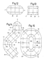
- FIG. 13 schematically shows a table with an essentially rectangular cross section, which is composed of two rectangular plate elements 26 and two narrower, rectangular end pieces 41 using corresponding connecting rods, indicated by dashed lines in FIG. 13.
- 6 shows a bottom view of the connection of an edge piece 41 to a plate element 26.
- pins 22, 23 are again provided, which engage in corresponding recesses 24 and 25, respectively.
- tunnel-like closed guide channels 42, 43 are provided, into which the ends of connecting rods 13, 14 can be inserted. Gags 19 allow the connecting rods 13, 14 to be locked in the guide channels 42, 43.
- screw bushings 8 are provided for fastening table legs 4, 5.
- the arrangement of these screw bushings is such that two bushings are provided on the plate element 26 and on the edge piece 41, respectively.
- the screwed table leg bridges the butt joint between plate element 26 and edge piece 41 and contributes to the firm connection of these parts. Even with two abutting plate elements 26, a screwed table leg would bridge the two elements.
- leveling screws 44 are provided, via which the table leg rests on the floor. These leveling screws allow the effective table leg length to be changed so that the table can be set up with a horizontal table top without wobbling. 7 and 8, the design and operation of a leveling screw 44 is shown.
- the leveling screw 44 comprises a threaded shaft 45 and a screw head 46.
- the shaft 45 is screwed into a nut 47 provided with a corresponding internal thread, which in turn is firmly connected to the lower end of the table leg 6.
- a thread-free collar 48 provided at the free end of the shaft 45 prevents the leveling screw 44 from being unscrewed from the nut 47.
- the screw 44 is thus captively connected to the table leg.
- the nut 47 consists of two half-shells 49, 51 enclosing the shaft, which have locking lugs 52 at their ends facing the table leg 6.
- a chamber is provided at the lower end of the table leg 6, which has an opening 53 adapted to the catch 52 in its bottom.
- a slot 54 provided between the locking lugs at the end of the half-shells 49, 51 gives the locking lugs 52 a resilient character.
- the two half shells 49, 51 are injection molded from plastic.
- the two half-shells 49, 51 can be connected to one another by a so-called plastic film hinge.
- the two half shells 49, 51 of the nut 47 are first placed around the shaft 45 of the screw 44.
- the half-shells with the enclosed threaded shaft are then introduced into the chamber mentioned in such a way that the latching noses penetrate the opening 53 in the bottom of the chamber and then snap behind the bottom. This fixes the whole arrangement on the table leg.
- An inner ring web 55 in the nut 47 interacts with the collar on the shaft 48 of the screw 44 and prevents the screw 44 from being completely unscrewed from the nut 47.
- the semicircular plate elements 2 the rectangular plate elements 26 and the edge pieces 41 are also sector-shaped plate elements 56.
- These sector-shaped elements 56 are each delimited by two straight sides 12 enclosing an angle of 45 ° and by two arcs 57, 58 of different radii.
- the length of the straight sides 12 corresponds to the length of the straight sides 12 of the semicircular plate element 2 and the longer side of the plate elements 26.
- FIG. 14 shows a multi-curved table, with two arms 59, 61 running at right angles to one another and a further, straight arm 62 which encloses an angle of 135 ° with arm 61. Between the arms 59, 61 two, between the arms 61 and 62 a sector-shaped plate element 56 are arranged.
- 15 shows a large oval table, the rounded sides of which are each formed by four sector-shaped plate elements 56. 15 has a central recess 63.
- the undersides of the sector-shaped plate elements 56 like the undersides of the semicircular and rectangular plate elements 2, 26 according to FIGS. 3 and 6, are formed, that is to say they are essentially provided with guide channels for connecting rods, the connecting rods in turn being held in the guide by locking members channels can be locked.
- the course of the guide channels and the connecting rods is indicated by dashed lines in FIGS. 14 and 15.
- the guide channels on the sector-shaped plate elements 56 each run perpendicular to the straight sides 12. They can also cut within a plate element 56 - as indicated in area D in FIG. 14 - in order to accommodate longer connecting rods in this way.
Landscapes
- Accommodation For Nursing Or Treatment Tables (AREA)
- Furniture Connections (AREA)
- Transition And Organic Metals Composition Catalysts For Addition Polymerization (AREA)
- Liquid Crystal (AREA)
- Acyclic And Carbocyclic Compounds In Medicinal Compositions (AREA)
- Machine Tool Units (AREA)
- Tables And Desks Characterized By Structural Shape (AREA)
- Mechanical Treatment Of Semiconductor (AREA)
- Control Of Eletrric Generators (AREA)
- Heat-Pump Type And Storage Water Heaters (AREA)
Priority Applications (1)
| Application Number | Priority Date | Filing Date | Title |
|---|---|---|---|
| AT86114304T ATE56127T1 (de) | 1985-10-25 | 1986-10-16 | Variabler tisch. |
Applications Claiming Priority (2)
| Application Number | Priority Date | Filing Date | Title |
|---|---|---|---|
| DE3538003 | 1985-10-25 | ||
| DE3538003A DE3538003C2 (de) | 1985-10-25 | 1985-10-25 | Variabler Tisch |
Publications (3)
| Publication Number | Publication Date |
|---|---|
| EP0220615A2 true EP0220615A2 (fr) | 1987-05-06 |
| EP0220615A3 EP0220615A3 (en) | 1988-02-03 |
| EP0220615B1 EP0220615B1 (fr) | 1990-09-05 |
Family
ID=6284454
Family Applications (1)
| Application Number | Title | Priority Date | Filing Date |
|---|---|---|---|
| EP86114304A Expired - Lifetime EP0220615B1 (fr) | 1985-10-25 | 1986-10-16 | Table variable |
Country Status (3)
| Country | Link |
|---|---|
| EP (1) | EP0220615B1 (fr) |
| AT (1) | ATE56127T1 (fr) |
| DE (2) | DE3538003C2 (fr) |
Cited By (3)
| Publication number | Priority date | Publication date | Assignee | Title |
|---|---|---|---|---|
| EP0804988A1 (fr) * | 1996-04-29 | 1997-11-05 | Selco Spa | Machine à couper et table accessoire |
| US6698363B2 (en) * | 2002-07-30 | 2004-03-02 | Outdoor Designs, Ltd. | Extendable table |
| EP1336354B1 (fr) * | 2002-02-18 | 2008-04-02 | Garten- und Landschaftsbau, Manfred Siegwarth | Table formée par un plateau de table divisible |
Families Citing this family (1)
| Publication number | Priority date | Publication date | Assignee | Title |
|---|---|---|---|---|
| CN107048691A (zh) * | 2016-11-10 | 2017-08-18 | 浙江捷昌线性驱动科技股份有限公司 | 一种长度可调的桌架及桌子 |
Family Cites Families (7)
| Publication number | Priority date | Publication date | Assignee | Title |
|---|---|---|---|---|
| US1800172A (en) * | 1928-05-25 | 1931-04-07 | Walter & Co B | Table lock |
| US2825613A (en) * | 1957-02-04 | 1958-03-04 | Henry J Gariepy | Table slides |
| US2955888A (en) * | 1958-10-16 | 1960-10-11 | Alfreda E Graves | Detachable extension table top |
| US3515077A (en) * | 1967-06-12 | 1970-06-02 | Matthew P Glowacki | Slide assembly for extendable tables |
| FR2070314A5 (fr) * | 1969-12-01 | 1971-09-10 | Jouk Leon | |
| US3974782A (en) * | 1975-06-09 | 1976-08-17 | Winzeler Stamping Co. | Slide assembly for extendable table |
| IL69877A0 (en) * | 1983-09-30 | 1983-12-30 | Shimshon Smadar | Extendable table |
-
1985
- 1985-10-25 DE DE3538003A patent/DE3538003C2/de not_active Expired - Fee Related
-
1986
- 1986-10-16 EP EP86114304A patent/EP0220615B1/fr not_active Expired - Lifetime
- 1986-10-16 DE DE8686114304T patent/DE3673946D1/de not_active Expired - Lifetime
- 1986-10-16 AT AT86114304T patent/ATE56127T1/de not_active IP Right Cessation
Cited By (3)
| Publication number | Priority date | Publication date | Assignee | Title |
|---|---|---|---|---|
| EP0804988A1 (fr) * | 1996-04-29 | 1997-11-05 | Selco Spa | Machine à couper et table accessoire |
| EP1336354B1 (fr) * | 2002-02-18 | 2008-04-02 | Garten- und Landschaftsbau, Manfred Siegwarth | Table formée par un plateau de table divisible |
| US6698363B2 (en) * | 2002-07-30 | 2004-03-02 | Outdoor Designs, Ltd. | Extendable table |
Also Published As
| Publication number | Publication date |
|---|---|
| EP0220615A3 (en) | 1988-02-03 |
| ATE56127T1 (de) | 1990-09-15 |
| EP0220615B1 (fr) | 1990-09-05 |
| DE3673946D1 (de) | 1990-10-11 |
| DE3538003C2 (de) | 1995-05-24 |
| DE3538003A1 (de) | 1987-04-30 |
Similar Documents
| Publication | Publication Date | Title |
|---|---|---|
| DE2625182C3 (de) | Beschlag zum losbaren Verbinden von zwei Bauteilen, insbesondere plattenförmigen Bauteilen fur Möbel | |
| DE3923996C2 (fr) | ||
| DE3687293T2 (de) | Vollstaendig gegliederte lagerungsvorrichtung. | |
| DE2548527C3 (de) | Beschlag zum lösbaren Verbinden zweier senkrecht aufeinanderstoßender Bauteile | |
| DE2715723A1 (de) | T-foermige konstruktionsverbindung | |
| EP0297033A2 (fr) | Elément de fixation pour une barre | |
| DE3905356C2 (fr) | ||
| DE9303798U1 (de) | Befestigungsvorrichtung für Möbelteile o.dgl. | |
| DE2610200A1 (de) | Beschlag zum loesbaren verbinden von bauteilen, insbesondere zum wieder loesbaren verbinden von plattenfoermigen bauteilen | |
| DE69808990T2 (de) | Verbindungseinrichtung für einen Treppenhandlauf | |
| DE3039389A1 (de) | Verbindung fuer rahmenteile von moebeln, insbesondere bueromoebeln | |
| DE2546749A1 (de) | Beschlag zum loesbaren verbinden zweier bauteile, insbesondere zweier senkrecht aufeinanderstossender plattenfoermiger bauteile | |
| DE3538003C2 (de) | Variabler Tisch | |
| DE3145825A1 (de) | Mechanische vorrichtung zur rechtwinkligen verbindung von flachen bauteilen | |
| DE2949436C2 (de) | Spannvorrichtung | |
| DE3147306C2 (de) | Leiter | |
| DE29505752U1 (de) | Vorrichtung zum Verbinden von Platten mittels Verschraubung | |
| DE3517184C2 (de) | Spannzange für eine stabförmige Schweißelektrode | |
| CH693422A5 (de) | Verbindungselement für Rahmenprofile. | |
| DE3001195A1 (de) | Schnappvorrichtung zur loesbaren verbindung von zwei teilen oder brettern | |
| DE69002342T2 (de) | Befestigungsvorrichtung durch Zusammenschrauben auf einem Profil, insbesondere auf einem Elektrizitätsschrank. | |
| DE3725111C2 (fr) | ||
| DE202008002419U1 (de) | Magazin zur Aufnahme mindestens einer Knochenschraube und Knochenplatte mit einem derartigen Magazin | |
| DE3119817A1 (de) | "klemmelement" | |
| DE19618655C2 (de) | Beschlaganordnung für die Verbindung zweier Bauteile, insbesondere Möbelteile |
Legal Events
| Date | Code | Title | Description |
|---|---|---|---|
| PUAI | Public reference made under article 153(3) epc to a published international application that has entered the european phase |
Free format text: ORIGINAL CODE: 0009012 |
|
| AK | Designated contracting states |
Kind code of ref document: A2 Designated state(s): AT CH DE FR LI NL |
|
| PUAL | Search report despatched |
Free format text: ORIGINAL CODE: 0009013 |
|
| AK | Designated contracting states |
Kind code of ref document: A3 Designated state(s): AT CH DE FR LI NL |
|
| 17P | Request for examination filed |
Effective date: 19880305 |
|
| 17Q | First examination report despatched |
Effective date: 19890807 |
|
| GRAA | (expected) grant |
Free format text: ORIGINAL CODE: 0009210 |
|
| AK | Designated contracting states |
Kind code of ref document: B1 Designated state(s): AT CH DE FR LI NL |
|
| PG25 | Lapsed in a contracting state [announced via postgrant information from national office to epo] |
Ref country code: NL Effective date: 19900905 Ref country code: FR Effective date: 19900905 |
|
| REF | Corresponds to: |
Ref document number: 56127 Country of ref document: AT Date of ref document: 19900915 Kind code of ref document: T |
|
| REF | Corresponds to: |
Ref document number: 3673946 Country of ref document: DE Date of ref document: 19901011 |
|
| PG25 | Lapsed in a contracting state [announced via postgrant information from national office to epo] |
Ref country code: AT Effective date: 19901016 |
|
| EN | Fr: translation not filed | ||
| NLV1 | Nl: lapsed or annulled due to failure to fulfill the requirements of art. 29p and 29m of the patents act | ||
| PLBE | No opposition filed within time limit |
Free format text: ORIGINAL CODE: 0009261 |
|
| STAA | Information on the status of an ep patent application or granted ep patent |
Free format text: STATUS: NO OPPOSITION FILED WITHIN TIME LIMIT |
|
| 26N | No opposition filed | ||
| PGFP | Annual fee paid to national office [announced via postgrant information from national office to epo] |
Ref country code: DE Payment date: 19920602 Year of fee payment: 6 |
|
| PG25 | Lapsed in a contracting state [announced via postgrant information from national office to epo] |
Ref country code: DE Effective date: 19930701 |
|
| PGFP | Annual fee paid to national office [announced via postgrant information from national office to epo] |
Ref country code: CH Payment date: 19930901 Year of fee payment: 8 |
|
| PG25 | Lapsed in a contracting state [announced via postgrant information from national office to epo] |
Ref country code: LI Effective date: 19941031 Ref country code: CH Effective date: 19941031 |
|
| REG | Reference to a national code |
Ref country code: CH Ref legal event code: PL |