EP0220749B1 - Verfahren zur Erhöhung der Durchflussgeschwindigkeit von Querstromfiltrationsanlagen - Google Patents
Verfahren zur Erhöhung der Durchflussgeschwindigkeit von Querstromfiltrationsanlagen Download PDFInfo
- Publication number
- EP0220749B1 EP0220749B1 EP86115347A EP86115347A EP0220749B1 EP 0220749 B1 EP0220749 B1 EP 0220749B1 EP 86115347 A EP86115347 A EP 86115347A EP 86115347 A EP86115347 A EP 86115347A EP 0220749 B1 EP0220749 B1 EP 0220749B1
- Authority
- EP
- European Patent Office
- Prior art keywords
- filtration
- flux
- flow
- cross
- tube
- Prior art date
- Legal status (The legal status is an assumption and is not a legal conclusion. Google has not performed a legal analysis and makes no representation as to the accuracy of the status listed.)
- Expired - Lifetime
Links
Images


Classifications
-
- B—PERFORMING OPERATIONS; TRANSPORTING
- B01—PHYSICAL OR CHEMICAL PROCESSES OR APPARATUS IN GENERAL
- B01D—SEPARATION
- B01D61/00—Processes of separation using semi-permeable membranes, e.g. dialysis, osmosis or ultrafiltration; Apparatus, accessories or auxiliary operations specially adapted therefor
- B01D61/14—Ultrafiltration; Microfiltration
- B01D61/22—Controlling or regulating
-
- B—PERFORMING OPERATIONS; TRANSPORTING
- B01—PHYSICAL OR CHEMICAL PROCESSES OR APPARATUS IN GENERAL
- B01D—SEPARATION
- B01D29/00—Filters with filtering elements stationary during filtration, e.g. pressure or suction filters, not covered by groups B01D24/00 - B01D27/00; Filtering elements therefor
- B01D29/11—Filters with filtering elements stationary during filtration, e.g. pressure or suction filters, not covered by groups B01D24/00 - B01D27/00; Filtering elements therefor with bag, cage, hose, tube, sleeve or like filtering elements
- B01D29/117—Filters with filtering elements stationary during filtration, e.g. pressure or suction filters, not covered by groups B01D24/00 - B01D27/00; Filtering elements therefor with bag, cage, hose, tube, sleeve or like filtering elements arranged for outward flow filtration
- B01D29/118—Filters with filtering elements stationary during filtration, e.g. pressure or suction filters, not covered by groups B01D24/00 - B01D27/00; Filtering elements therefor with bag, cage, hose, tube, sleeve or like filtering elements arranged for outward flow filtration open-ended
-
- B—PERFORMING OPERATIONS; TRANSPORTING
- B01—PHYSICAL OR CHEMICAL PROCESSES OR APPARATUS IN GENERAL
- B01D—SEPARATION
- B01D29/00—Filters with filtering elements stationary during filtration, e.g. pressure or suction filters, not covered by groups B01D24/00 - B01D27/00; Filtering elements therefor
- B01D29/62—Regenerating the filter material in the filter
- B01D29/66—Regenerating the filter material in the filter by flushing, e.g. counter-current air-bumps
-
- B—PERFORMING OPERATIONS; TRANSPORTING
- B01—PHYSICAL OR CHEMICAL PROCESSES OR APPARATUS IN GENERAL
- B01D—SEPARATION
- B01D65/00—Accessories or auxiliary operations, in general, for separation processes or apparatus using semi-permeable membranes
- B01D65/02—Membrane cleaning or sterilisation ; Membrane regeneration
-
- B—PERFORMING OPERATIONS; TRANSPORTING
- B01—PHYSICAL OR CHEMICAL PROCESSES OR APPARATUS IN GENERAL
- B01D—SEPARATION
- B01D2315/00—Details relating to the membrane module operation
- B01D2315/10—Cross-flow filtration
-
- B—PERFORMING OPERATIONS; TRANSPORTING
- B01—PHYSICAL OR CHEMICAL PROCESSES OR APPARATUS IN GENERAL
- B01D—SEPARATION
- B01D2321/00—Details relating to membrane cleaning, regeneration, sterilization or to the prevention of fouling
- B01D2321/16—Use of chemical agents
- B01D2321/162—Use of acids
Definitions
- the present invention relates to a method of increasing the time averaged cross-flow filtration flux in accordance with the generic clause of Claim 1.
- clarifiers and through-flow filters are conventionally used for removal of suspended and colloidal solids. Such systems have inherent disadvantages. Without preclarification, most filters are unable to handle the resulting higher solids loadings. Likewise, even with a clarifier in the process train, filtered particles continuously accumulate on and within through-flow filter media. The filter flux rate decreases with time (or headless increases) and frequent backwashing is required to remove the accumulated solids from the filter medium. When product water is used for back-washing there is a significant net decrease in total water production. Relatively large volumes of low solids wastewater are also created which must receive some type of further handling. There is also the problem of filter break-through. Moreover, water quality is extremely process dependent.
- Cross-flow filtration is substantially different from through-flow filtration, in that feed water is introduced parallel to the filter surface, and filtration occurs in a direction perpendicular to the direction of the feed flow.
- Cross-flow filtration satisfies a much wider range of applications and provides economic benefits that other conventional options do not.
- Cross-flow filtration systems are capable of clarification, filtration, and thickening in one process step. Equipment costs approach those of direct filtration; yet cross-flow filtration is capable of filtering streams that contain suspended solids concentrations of 10,000 mg/l or higher.
- cross-flow systems require less space than conventional systems.
- Cross-flow filtration systems include membrane systems such as microfiltration, reverse osmosis and ultrafiltration.
- HYDROPERM tubes differ from conventional membrane ultrafilters, in that they have pore sizes on the order of several microns, wherein the length of a pore is many times that of its diameter. These tubes are described in greater detail, for example, in “HYDROPERM”' CROSS FLOW MICROFILTRATION", Daniel L. Comstock, et al., Neptune Microfloc, Inc. Report No. KT 7307, May 1982, and in Report No. 77-ENAS-51 of the American Society of Mechanical Engineers, entitled "Removal of Suspended and Colloidal Solids from Waste Streams by the use of Cross-Flow Microfiltration".
- Feed flow is through the centre of HYDROPERM"' tubes at a relatively low pressure, typically less than 2.07 x 10⁵ N/m2.
- the filtrate is typically collected in a jacket surrounding the exterior tube wall and withdrawn therefrom by a product line.
- solid particles are slowly driven with the product flow toward the tube wall.
- concentration of particles in regions close to the wall steadily increases.
- cross-flow filtration systems In cross-flow filtration systems generally, because the direction of the feed flow is tangential to the filter surface, accumulation of the filtered solids on the filtering medium is reduced by the shearing action of the flow. Cross-flow filtration thus affords the possibility of a quasi-steady state operation with a nearly constant flux when the driving pressure differential is held constant. Unfortunately, this theoretical possibility has not been achieved in practice. Thus, the problem of declining filtration fluxes has plagued conventional cross-flow filtration systems.
- any liquid from which suspended solids removal is desired will contain a wide range of particular sizes, ranging in effective diameter from several microns down to colloidal dimensions. Because of the "in-depth" filtration characteristics of thick-walled, thermoplastic tubes, such as HYDROPERM"' tubes, particles smaller than the largest pore size of the tube may, under certain circumstances, enter the wall matrix. In any event, above a certain solids concentration in the feed, the majority of the suspended solids are retained at the inner wall of the tube and quickly form a dynamic membrane (also referred to as a "filter cake” or “sludge layer”). The dynamic membrane is, we believe, largely responsible for the filtration which subsequently occurs.
- cleaning techniques have previously been investigated for restoring the filtration flux value.
- cleaning techniques have involved chemical and/or physical cleaning of the surface of the filter medium.
- chemical solvents have been used to dissolve the layer-building filtered particles so as to yield a clean, layer-free filter surface.
- Hydrochloric acid and other acids are examples of solvents commonly being used.
- a simple physical cleaning technique commonly used is backflushing of the filter medium, i.e., temporary reversal of the filtrate flow direction. This cleaning technique is frequently used in conjunction with cross-flow filtration processes utilizing hollow tubular filters.
- Another physical cleaning technique employed in the art involves periodically increasing the recycle velocity longitudinally through the porous tubes. (See, e.g., EP-A-79040). Higher recycle rates tend to sweep away accumulated deposits, thus minimizing the build-up of the filter cake within the tubes.
- cross-flow filtration art continues to search for new techniques for increasing time-averaged filtration fluxes, in order to make cross-flow filtration processess more economical.
- the degree of flux enhancement obtained by the above described method and apparatus depends to varying degrees upon the characteristics of the particular liquid feed being processed, and particularly the chemicals, if any, added as pretreatment, and the characteristics of the suspended solids, as well as various operational parameters of the overall cross-flow filtration process, including the filter tube cleaning techniques utilised, e.g., backflushing, periodically increasing recycle velocity through the tubes, and acid cleaning, by flowing the acid solution which can contain a hydrochloria acid, laterally over the surface of the filter medium while simultaneously temporarily eliminating the pressure differential across the filter medium.
- the filter medium comprises a filter tube and the filtrate which is permeated through the filter tube wall is collected in a closed jacket surrounding the filter tube, and the variable throttling pressure is applied to a product line exiting from the jacket.
- the present invention can be combined with conventional flux enhancement techniques such as, for example, back flushing and periodically increasing recycle velocity.
- Cross-flow filtration in accordance with the invention may be accomplished, for example, using thick-walled, microporous thermoplastic tubes.
- These tubes can be made from a wide variety of extrudable thermoplastics, such as, for example, nylon or polyethylene, and typically have walls of about one millimeter in thickness.
- extrudable thermoplastics such as, for example, nylon or polyethylene
- such tubes may, for example, possess a dominant pore size on the order of about one to ten microns and a porosity on the order of about 65% i.e., the pores cover 65% of the surface area of the tubes.
- FIG. 1 A schematic view of cross-flow filtration through such a thick-walled, microporous thermoplastic tube is shown in Fig. 1.
- a liquid feed flows through the inside of the tube at relatively low pressures, e.g., (1.4 to 34.5) x 104 N/m2, and filtrate permeation occurs through the tube wall, which is relatively thick, e.g. on the order of about one millimeter.
- Flux rates (F) observed during the non-equilibrium phase of such flux/time curves are proportional to the feed velocity (V), the pressure differential ( ⁇ P) and time (t) according to the following general relationship: F ⁇ V a ⁇ p b ⁇ t -c
- non-equilibrium flux rates i.e., fluxes in the non-equilibrium phase
- equilibrium flux rates i.e., fluxes in the equilibrium phase
- the advantages of product throttling in cross-flow filtration systems include: (1) the ability to maintain flux rates at higher than equilibrium (plateau) values; (2) reduction of the compressive forces acting on the dynamic membrane formed on the interior tube surface (such forces lead to reduced flux rates and possible tube matrix plugging); (3) reduction of the rate of deposition (i.e., growth) of the dynamic membrane; and (4) the ability to maintain a constant flow rate to downstream equipment requiring same, e.g., reverse osmosis units.
- Fig. 3 is a schematic flow diagram, in partial cross section, showing a simplified embodiment of a filtration tube module constructed in accordance with the present invention utilizing product line throttling.
- the suspended solids (and/or emulsified oil) laden liquid to be filtered flows through a filter tube module 10 in the direction shown by the arrows.
- tube module 10 includes a single microporous filter tube 11 (e.g., a HYDROPERM'" tube) encased within a closed filtrate collection jacket 12.
- commercial scale tube modules 10 will include a plurality (as many as hundreds) of filter tubes 11 arranged in a parallel tube bundle (not shown) within a single jacket 12.
- a conventional inlet (circulation) pump (not shown) provides the requisite inlet pressure (P1) and liquid flow velocity (V1) in feed line 13.
- a portion of the liquid is permeated transversely through the wall of filter tube 11 in the direction shown by the arrows, thereby depositing at least a portion of the solids/emulsified oil on the inner surface of tube 11 as a dynamic membrane (not shown), as discussed previously.
- the liquid permeated through filter tube 11 i.e. the filtrate
- the filtrate exit pressure in product line 15, designated (P3) is essentially zero in conventional cross-flow filtration systems.
- Product line throttling is achieved by placing a flow controller (e.g. a Griswald flow controller - not shown) or a pressure regulator 20 and valve 19 in tandem in product line 15, as shown, and by partially closing valve 19.
- Product line throttling can be used to maintain a constant flux rate over the entire length of a filtration run by continually increasing the pressure differential throughout the run.
- the pressure differential can be increased by reducing the value of P3 by reducing the throttling pressure appliced to product line 15 (using valve 19 and pressure regulator 20).
- the filter tube inlet pressure P1 is initially 2,07 x 10⁵ N/m2
- the initial product line pressure P3 in conventional cross-flow filtration devices is 0 psi, so that the initial pressure differential ⁇ P (driving pressure) is approximately 2,07 x 10⁵ N/m2.
- the pressure differential remains substantially constant over time, so that the pressure differential at the end of the filtration run will continue to be on the order of 2,07 x 10⁵ N/m2.
- the flux rate will decline rapidly until the plateau flux is reached.
- Flux enhancement is achieved by throttling the product line pressure P3, using pressure regulator 20 and valve 19.
- the initial product line pressure P3 in the present invention can be throttled so as to provide the initial pressure differential required to provide a desired constant flux rate at start up.
- P3 might be throttled to 20 psi initially, thus producing an initial pressure differential of 3.4 x 10⁴ N/m2.
- the flux rate is selected based on practical economic factors presented by the particular filtration application of concern; but in every case it will be higher than the plateau flux reached if product throttling were not employed.
- the time-averaged flux rate over the entire run will be higher than that of conventional systems.
- the product line (throttling) pressure P3 can continually be reduced, thus increasing the pressure differential ( ⁇ P) in order to maintain the flux rate at the desired constant value.
- ⁇ P pressure differential
- the driving pressure ⁇ P will increase to the value of the average of the inlet pressure P1 and the outlet pressure P2, with P3 being reduced to zero at the end of the filtration run.
- the system will resemble a conventional system, and flux decline to the equilibrium (plateau) flux rate will occur.
- the selection of the values for the initial inlet pressure P1, the initial product line pressure P3 (i.e., the throttling pressure initially applied), and the constant flux rate will depend on such practical factors as the desired length of the filtration run (i.e., the number of hours the filtration device must routinely operate before it can be shut down for cleaning), the volume of liquid to be filtered during such runs, and the cost of the equipment required to generate the inlet and throttling pressures.
- the value of the initial inlet pressure P1 will be within the range of from about 1,7 x 10⁵ N/m2 to about 2,8 x 10⁵ N/m2
- the value of the initial product line (throttling) pressure P3 will be within the range of from about 1,38 x 10⁵ to about 2,4 x 10⁵ N/m2
- the lower limit of ⁇ P (pressure differential) will be within the range of from about 1,4 x 10⁴ to about 4,1 x 10⁴ N/m2, still more preferably on the order of about 3,4 x 10⁴ N/m2 and the upper limit of ⁇ P will be about 2,8 x 10⁵ N/m2.
- Product line throttling as described above, can preferably be practiced in combination with another novel flux enhancement technique which we have discovered, namely, slow start up of the liquid flow transversely through the filter medium at the beginning of the filtration run.
- the method of the present invention comprises the step of commencing the filtration run by gradually increasing the flow rate of the filtrate from essentially zero (at start up) to the desired operational flow rate over a sufficiently extended period of time to substantially prevent deleterious intrusion of the particles of material being filtered out of the liquid into the filter tube matrix.
- extended period of time is preferably within the range of from about 15 seconds to about 60 seconds, and still more preferably, from about 30 seconds to about 45 seconds.
- Such slow start up of the liquid flow through the filter medium yields longer filtration runs (lower pressure differentials ⁇ P) both when accompanying product line throttling according to the present invention and when practiced alone.
- such slow start up is accomplished by beginning the filtration run with product line throttling valve 19 (Fig. 3) fully closed, and then gradually (and preferably steadily) opening valve 19 slowly over the time periods noted above.
- Product line throttling and/or slow start up are preferably practiced in combination with another flux enhancement technique namely, product port closure during cleaning.
- this method comprises the steps of cleaning the surface of the filter medium prior to commencement of the filtration run by flowing a cleaning solution laterally over the surface of the filter medium while simultaneously temporarily eliminating the pressure differential ⁇ P across the filter medium, preferably by blocking all flow from jacket 12 (Fig. 3), e.g., by closing product port 14 (using, for example, a conventional valve, not shown) or by fully closing valve 19 in product line 15.
- the cleaning solution may contain hydrochloric acid.
- each such backflushing pulse is preferably about 2 seconds, and the interval between backflushings is preferably within the range of from about 1 minute to about 2 minutes.
- the backflushing pressure is preferably on the order of about 3,4 x 10⁵ N/m2.
- recycle velocity is also possible to periodically increase the recycle velocity of the liquid flowing laterally along the surface of the filter medium, with the duration of each such periodic increase being with the range of from about 5 to about 60 seconds, and the interval between such periodic velocity increases not exceeding about 20 minutes.
- the recycle velocity is preferably increased to a value within the range of from about 3.5 to about 7m per sec., using techniques such as those disclosed in EP-A-79040.
- Back flushing was accomplished once per minute by opening valves 37 and 32 for 2 seconds and closing product line valve 38 for the same period of time, using product water as the backflushing liquid and a driving pressure of 3,1 x 10⁵ N/m2, in the manner discussed previously.
- Fig. 6 is a graph showing the test results.
- Water from a small plastic recycle tank 45 was pumped at about 1,35 x 10⁵ N/m2 by a conventional feed pump 46 to a single 6mm inner diameter, 0,91m long HYDROPERM"' tube 47 encased in a filtrate collection jacket 48 to form a module 49. Filtrate was removed on the shell side 50 of the module 49, and exited from the module via exit ports 51 in jacket 48 fluidly connected to product line 52. The remaining recycle flow 53 was piped back to holding tank 45. For test purposes, product water (i.e., filtrate) was also added back to holding tank 45 to provide a closed loop system.
- product water i.e., filtrate
- the tests were conducted with 50 mg-l of commercial grade ferric sulfate and 0.2 mg/l of a catonic polymer (Allied® 776) added to tap water in holding tank 45.
- the ferric sulfate immediately hydrolyzed to form a suspension of ferric hydroxide that served as filterable material for the experiments.
- the polymer was added to improve the rheological quality of the solids.
- Perioda Pulse Physical cleaning by periodically increasing recycle velocity
- the recycle velocity varied from 1,34m per sec. during filtration to 3,8m per sec. during the Perma Pulse mode of operation.
- the frequency between increases in recycle velocity was set at 2 minutes and the duration of each pulse was 15 seconds.
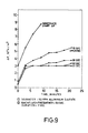
- Fig. 8 The results of a further set of experiments using the Fig. 5 test apparatus are plotted in Fig. 8.
- a Perma Pulse plus slow startup run and a slow startup only run were contrasted to a run made with no flux enhancement procedures whatsoever.
- the Perma Pulse experiments were conducted in the slow startup mode, as described herein, in which product line 52 was steadily opened over a 1 minute period using valve 55.
- Perma Pulse frequency was 2 minutes with a duration of 15 seconds. Fluxes from all runs were seen to decline to an equilibrium value in about 90 minutes.
- the equilibrium flux for Perma Pulse plus slow startup was about 30 percent greater than that observed in the non-flux enhanced run. Perma Pulse equilibrium flux was about 17 percent higher than the equilibrium value of the run that incorporated slow startup only.
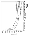
- Fig. 9 is a graph plotting pressure differential ( ⁇ P) vs. time, showing the results of another set of experiments conducted using the Fig. 5 test apparatus.
- These tests investigated slow startup by gradually opening product line valve 55 over different periods of time. The flux rate was held constant by product line throttling, as described herein. As can be seen, the beneficial effects of slow startup, in terms of a lower driving pressure ( ⁇ P), are achieved for startup periods ranging from about 15 seconds to about 45 seconds, with gradual steady opening of product line valve 55 over a period of 45 seconds showing the best results.
- ⁇ P lower driving pressure
- These tests were conducted with sea water plus 50 ppm aluminium sulfate as the filterable material, and utilized backflushing (as described previously) at a frequency of 60 seconds with a duration of 2 seconds (backflushing pump not shown).
- Fig. 10 is a graph plotting pressure differential ( ⁇ P) vs. time, showing the results of an additional set of experiments conducted using the Fig. 5 test apparatus. These tests compared a filtration run following acid cleaning during which product line valve 55 was opened with a filtration run following acid cleaning during which product line valve 55 was closed. The beneficial results of product port closure during acid cleaning can be readily seen, in terms of the lower driving pressure ( ⁇ P) experienced.
- the test conditions were essentially identical to those described above in connection with Fig. 9, including the use of backflushing.
Landscapes
- Chemical & Material Sciences (AREA)
- Chemical Kinetics & Catalysis (AREA)
- Engineering & Computer Science (AREA)
- Water Supply & Treatment (AREA)
- Separation Using Semi-Permeable Membranes (AREA)
- Filtration Of Liquid (AREA)
Claims (2)
- Verfahren zur Erhöhung des zeitgemittelten Durchflusses einer Flüssigkeit durch ein poröses Filtermedium (11, 47) bei der Querstromfiltration über die Dauer eines Filtrationslaufs, das einen Schritt umfaßt, bei dem Flüssigkeit quer durch das Filtermedium (11, 47) fließt, indem eine Druckdifferenz über dem Filtermedium (11, 47) erzeugt wird,
dadurch gekennzeichnet,
daß das Verfahren den weiteren Schritt umfaßt, daß man den Filtrationslauf beginnt, indem man die Fließgeschwindigkeit des Filtrats von im wesentlichen Null auf die gewünschte Betriebsfließgeschwindigkeit über eine Zeitdauer von wenigstens 15 Sekunden ansteigen läßt, um so im wesentlichen das Eindringen von Partikeln des zu filternden Materials aus der Flüssigkeit in das Filtermedium (11, 47) als solches zu verhindern. - Verfahren nach Anspruch 1,
dadurch gekennzeichnet,
daß die Zeitdauer zwischen 15 bis 45 Sekunden beträgt.
Applications Claiming Priority (2)
| Application Number | Priority Date | Filing Date | Title |
|---|---|---|---|
| US47481783A | 1983-03-10 | 1983-03-10 | |
| US474817 | 1983-03-10 |
Related Parent Applications (2)
| Application Number | Title | Priority Date | Filing Date |
|---|---|---|---|
| EP84102529A Division EP0122439A3 (de) | 1983-03-10 | 1984-03-08 | Verfahren und Vorrichtung zur Erhöhung der Durchflussgeschwindigkeit von Querstromfiltrationsanlagen |
| EP84102529.9 Division | 1984-03-08 |
Publications (3)
| Publication Number | Publication Date |
|---|---|
| EP0220749A2 EP0220749A2 (de) | 1987-05-06 |
| EP0220749A3 EP0220749A3 (en) | 1987-12-16 |
| EP0220749B1 true EP0220749B1 (de) | 1992-08-12 |
Family
ID=23885058
Family Applications (2)
| Application Number | Title | Priority Date | Filing Date |
|---|---|---|---|
| EP86115347A Expired - Lifetime EP0220749B1 (de) | 1983-03-10 | 1984-03-08 | Verfahren zur Erhöhung der Durchflussgeschwindigkeit von Querstromfiltrationsanlagen |
| EP84102529A Ceased EP0122439A3 (de) | 1983-03-10 | 1984-03-08 | Verfahren und Vorrichtung zur Erhöhung der Durchflussgeschwindigkeit von Querstromfiltrationsanlagen |
Family Applications After (1)
| Application Number | Title | Priority Date | Filing Date |
|---|---|---|---|
| EP84102529A Ceased EP0122439A3 (de) | 1983-03-10 | 1984-03-08 | Verfahren und Vorrichtung zur Erhöhung der Durchflussgeschwindigkeit von Querstromfiltrationsanlagen |
Country Status (4)
| Country | Link |
|---|---|
| EP (2) | EP0220749B1 (de) |
| JP (1) | JPH0669530B2 (de) |
| CA (1) | CA1272138A (de) |
| DE (1) | DE3485871T2 (de) |
Cited By (1)
| Publication number | Priority date | Publication date | Assignee | Title |
|---|---|---|---|---|
| KR101951862B1 (ko) * | 2017-09-15 | 2019-02-26 | 한국에너지기술연구원 | 크로스 플로우 유체여과장치 |
Families Citing this family (16)
| Publication number | Priority date | Publication date | Assignee | Title |
|---|---|---|---|---|
| JPS61161114A (ja) * | 1985-01-04 | 1986-07-21 | Toshiba Ceramics Co Ltd | セラミツクフイルタ−の濾過装置およびその洗浄方法 |
| JPS6227010A (ja) * | 1985-07-25 | 1987-02-05 | Shokuhin Sangyo Maku Riyou Gijutsu Kenkyu Kumiai | 逆浸透処理方法 |
| ZA87553B (en) * | 1986-01-31 | 1988-03-30 | Water Res Commission | Dewatering slurries |
| FI81137B (fi) * | 1986-12-17 | 1990-05-31 | Ahlstroem Oy | Foerfarande och anordning foer urvattning av fibersuspensioner. |
| FR2609645B1 (fr) * | 1987-01-21 | 1989-03-24 | Alsthom Cgee | Installation de filtration modulaire automatique |
| JPH01143606A (ja) * | 1987-11-30 | 1989-06-06 | Showa Alum Can Kk | 濾過膜の洗浄方法 |
| DE3819704C1 (de) * | 1988-06-09 | 1989-09-28 | Kraft Europe R & D, Inc. Zweigniederlassung Muenchen, 8000 Muenchen, De | |
| JP2519969Y2 (ja) * | 1989-07-27 | 1996-12-11 | 新技術工営 株式会社 | 加圧搬送機による建設泥土の脱水装置 |
| US5256294A (en) * | 1990-09-17 | 1993-10-26 | Genentech, Inc. | Tangential flow filtration process and apparatus |
| FR2668078B1 (fr) * | 1990-10-17 | 1992-12-24 | Dumez Lyonnaise Eaux | Procede pour le retrolavage de membrane tubulaires de filtration, et dispositif de mise en óoeuvre. |
| JPH0631141A (ja) * | 1992-07-22 | 1994-02-08 | Kubota Corp | 固液分離方法 |
| FR2746448B1 (fr) * | 1996-03-21 | 1998-04-30 | Snecma | Circuit d'alimentation de carburant permettant la decontamination du debit dose injecte |
| NL1025717C2 (nl) * | 2004-03-12 | 2005-09-13 | Vitens Fryslon N V | Werkwijze voor het zuiveren van een waterige stroom. |
| FR2888582B1 (fr) * | 2005-07-15 | 2010-08-20 | Solvay | Procede de preparation d'un polymere halogene et dispositif pour sa mise en oeuvre |
| US10486089B2 (en) | 2011-04-05 | 2019-11-26 | Grundfos Holding A/S | Method and system for filtration and filtration cake layer formation |
| US12409417B2 (en) | 2019-09-26 | 2025-09-09 | Sabic Global Technologies B.V. | Start-up procedure for rapid attainment of optimal steady-state performance in membrane separation |
Family Cites Families (5)
| Publication number | Priority date | Publication date | Assignee | Title |
|---|---|---|---|---|
| FR2136995B2 (de) * | 1971-05-11 | 1973-07-13 | Tunzini Sames | |
| CA981595A (en) * | 1972-06-15 | 1976-01-13 | Dorr-Oliver Incorporated | Defouling ultrafiltration cells |
| SE396017B (sv) * | 1974-12-23 | 1977-09-05 | Alfa Laval Ab | Filtreringsforfarande, serskilt for ultrafiltrering |
| SE434914B (sv) * | 1975-07-07 | 1984-08-27 | Jonsson U R S | Forfarande for att ur en suspension av bakterier och ett vetskeformigt medium genom filtrering avskilja mediet under samtidig anrikning av bakterierna |
| JPS5626503A (en) * | 1979-08-10 | 1981-03-14 | Hitachi Ltd | Removing solid material from liquid |
-
1984
- 1984-03-08 JP JP59043017A patent/JPH0669530B2/ja not_active Expired - Lifetime
- 1984-03-08 EP EP86115347A patent/EP0220749B1/de not_active Expired - Lifetime
- 1984-03-08 DE DE8686115347T patent/DE3485871T2/de not_active Expired - Fee Related
- 1984-03-08 EP EP84102529A patent/EP0122439A3/de not_active Ceased
- 1984-03-09 CA CA000449315A patent/CA1272138A/en not_active Expired
Cited By (1)
| Publication number | Priority date | Publication date | Assignee | Title |
|---|---|---|---|---|
| KR101951862B1 (ko) * | 2017-09-15 | 2019-02-26 | 한국에너지기술연구원 | 크로스 플로우 유체여과장치 |
Also Published As
| Publication number | Publication date |
|---|---|
| JPH0669530B2 (ja) | 1994-09-07 |
| EP0122439A3 (de) | 1985-05-29 |
| DE3485871T2 (de) | 1993-01-21 |
| EP0220749A3 (en) | 1987-12-16 |
| DE3485871D1 (de) | 1992-09-17 |
| EP0220749A2 (de) | 1987-05-06 |
| JPS59209613A (ja) | 1984-11-28 |
| CA1272138A (en) | 1990-07-31 |
| EP0122439A2 (de) | 1984-10-24 |
Similar Documents
| Publication | Publication Date | Title |
|---|---|---|
| US5047154A (en) | Method and apparatus for enhancing the flux rate of cross-flow filtration systems | |
| US4670150A (en) | Cross-flow microfiltration lime softener | |
| EP0220749B1 (de) | Verfahren zur Erhöhung der Durchflussgeschwindigkeit von Querstromfiltrationsanlagen | |
| AU576424B2 (en) | Concentration of solids in a suspension | |
| US4931186A (en) | Concentration of solids in a suspension | |
| US5024762A (en) | Concentration of solids in a suspension | |
| EP0079040A2 (de) | Verfahren und Vorrichtung zur Erhöhung des Durchflusses bei der Querstromfiltration von suspendierte Feststoffe enthaltenden Flüssigkeiten | |
| Ognier et al. | Characterisation and modelling of fouling in membrane bioreactors | |
| US5500134A (en) | Microfiltration system with swirling flow around filter medium | |
| US20020046974A1 (en) | Method and apparatus for microfiltration | |
| JPH07112185A (ja) | 排水処理装置およびその洗浄方法 | |
| EP0131119B1 (de) | Enthärtung mittels Kalk und Querstrommikrofiltration | |
| Schneider et al. | The concentration of suspensions by means of crossflow-microfiltration | |
| Scott et al. | Crossflow microfiltration of organic/water suspensions | |
| EP0121785A2 (de) | Verfahren und Vorrichtung zur Erhöhung der Durchflussgeschwindigkeit von Querstromfiltrationsanlagen | |
| JP6264095B2 (ja) | 膜モジュールの洗浄方法 | |
| Roh et al. | Backflushing, pulsation and inline flocculation techniques for flux improvement in crossflow microfiltration | |
| JPH08502923A (ja) | 交差流ミクロ濾過法 | |
| Fukada et al. | Fouling performance in the filtration of water containing humic acid and/or kaolin with microporous membrane | |
| CA1315209C (en) | Concentration of solids in a suspension | |
| JP7213711B2 (ja) | 水処理装置および水処理方法 | |
| JP3223568B2 (ja) | 水処理装置 | |
| US20230019509A1 (en) | Methods and apparatus for removing contaminants from an aqueous material | |
| Bhave | Liquid filtration and separation with inorganic membranes: operating considerations and some aspects of system design | |
| SU1639717A1 (ru) | Способ фильтровани жидкости |
Legal Events
| Date | Code | Title | Description |
|---|---|---|---|
| PUAI | Public reference made under article 153(3) epc to a published international application that has entered the european phase |
Free format text: ORIGINAL CODE: 0009012 |
|
| AC | Divisional application: reference to earlier application |
Ref document number: 122439 Country of ref document: EP |
|
| AK | Designated contracting states |
Kind code of ref document: A2 Designated state(s): BE DE FR GB IT NL |
|
| RIN1 | Information on inventor provided before grant (corrected) |
Inventor name: HAGEN, ROBERT DOUGLAS Inventor name: COMSTOCK, DANIEL LEE |
|
| PUAL | Search report despatched |
Free format text: ORIGINAL CODE: 0009013 |
|
| AK | Designated contracting states |
Kind code of ref document: A3 Designated state(s): BE DE FR GB IT NL |
|
| 17P | Request for examination filed |
Effective date: 19880303 |
|
| RAP1 | Party data changed (applicant data changed or rights of an application transferred) |
Owner name: JOHNSON FILTRATION SYSTEMS INC. |
|
| 17Q | First examination report despatched |
Effective date: 19890608 |
|
| RAP1 | Party data changed (applicant data changed or rights of an application transferred) |
Owner name: C.P.C. ENGINEERING CORP. |
|
| GRAA | (expected) grant |
Free format text: ORIGINAL CODE: 0009210 |
|
| ITF | It: translation for a ep patent filed | ||
| AC | Divisional application: reference to earlier application |
Ref document number: 122439 Country of ref document: EP |
|
| AK | Designated contracting states |
Kind code of ref document: B1 Designated state(s): BE DE FR GB IT NL |
|
| REF | Corresponds to: |
Ref document number: 3485871 Country of ref document: DE Date of ref document: 19920917 |
|
| ET | Fr: translation filed | ||
| ITTA | It: last paid annual fee | ||
| PLBE | No opposition filed within time limit |
Free format text: ORIGINAL CODE: 0009261 |
|
| STAA | Information on the status of an ep patent application or granted ep patent |
Free format text: STATUS: NO OPPOSITION FILED WITHIN TIME LIMIT |
|
| 26N | No opposition filed | ||
| PGFP | Annual fee paid to national office [announced via postgrant information from national office to epo] |
Ref country code: FR Payment date: 19970421 Year of fee payment: 14 |
|
| PGFP | Annual fee paid to national office [announced via postgrant information from national office to epo] |
Ref country code: NL Payment date: 19970424 Year of fee payment: 14 |
|
| PGFP | Annual fee paid to national office [announced via postgrant information from national office to epo] |
Ref country code: GB Payment date: 19970425 Year of fee payment: 14 |
|
| PGFP | Annual fee paid to national office [announced via postgrant information from national office to epo] |
Ref country code: DE Payment date: 19970428 Year of fee payment: 14 |
|
| PGFP | Annual fee paid to national office [announced via postgrant information from national office to epo] |
Ref country code: BE Payment date: 19970429 Year of fee payment: 14 |
|
| PG25 | Lapsed in a contracting state [announced via postgrant information from national office to epo] |
Ref country code: GB Free format text: LAPSE BECAUSE OF NON-PAYMENT OF DUE FEES Effective date: 19980308 |
|
| PG25 | Lapsed in a contracting state [announced via postgrant information from national office to epo] |
Ref country code: FR Free format text: THE PATENT HAS BEEN ANNULLED BY A DECISION OF A NATIONAL AUTHORITY Effective date: 19980331 Ref country code: BE Free format text: LAPSE BECAUSE OF NON-PAYMENT OF DUE FEES Effective date: 19980331 |
|
| BERE | Be: lapsed |
Owner name: C.P.C. ENGINEERING CORP. Effective date: 19980331 |
|
| PG25 | Lapsed in a contracting state [announced via postgrant information from national office to epo] |
Ref country code: NL Free format text: LAPSE BECAUSE OF NON-PAYMENT OF DUE FEES Effective date: 19981001 |
|
| GBPC | Gb: european patent ceased through non-payment of renewal fee |
Effective date: 19980308 |
|
| NLV4 | Nl: lapsed or anulled due to non-payment of the annual fee |
Effective date: 19981001 |
|
| PG25 | Lapsed in a contracting state [announced via postgrant information from national office to epo] |
Ref country code: DE Free format text: LAPSE BECAUSE OF NON-PAYMENT OF DUE FEES Effective date: 19981201 |
|
| REG | Reference to a national code |
Ref country code: FR Ref legal event code: ST |